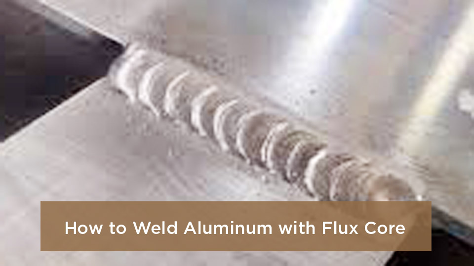
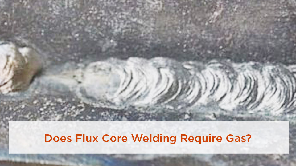
Flux-cored arc welding is often the process people reach for when a steel repair is too heavy for thin-sheet methods or the job must be done outdoors. I first understood its appeal on a thick trailer-frame repair: the wire fed continuously, the arc stayed productive, and self-shielded wire did not need a gas cylinder. The tradeoff was more smoke, slag, spatter, and a much smaller margin for unsafe shortcuts.
This guide explains what flux core welding is used for, how self-shielded and gas-shielded FCAW differ, which materials and jobs suit the process, what equipment you need, and how to set up a basic steel T-joint. It also explains where FCAW is a poor choice and why the wire manufacturer’s data sheet or an approved welding procedure specification must always override generic settings.
Quick Answer
Flux core welding is mainly used for structural steel, heavy fabrication, equipment repair, shipbuilding, field erection, and other jobs that need high productivity on medium-to-thick steel. Self-shielded wire is useful outdoors, while gas-shielded wire is common in shops. It is usually not the best choice for very thin sheet metal.
Key Takeaways
- Flux-cored arc welding, or FCAW, uses a continuously fed tubular wire electrode that contains flux.
- Self-shielded FCAW is portable and handles outdoor drafts better because it does not rely on an external shielding-gas cloud.
- Gas-shielded FCAW is productive on thicker steel but still needs protection from wind and the exact gas listed for the wire.
- Polarity, voltage, wire-feed speed, stickout, shielding gas, and position must match the specific wire data sheet or approved WPS.
- FCAW creates fumes, ultraviolet radiation, hot slag, sparks, and fire risks. Ventilation, PPE, fire control, and proper training are essential.
At a Glance
| Time Required | About 30–60 minutes to set up and practice a basic T-joint; longer for preparation, multiple passes, or inspection |
| Difficulty | Beginner-friendly for practice beads; moderate to advanced for load-bearing, out-of-position, code, or multi-pass work |
| Tools Needed | FCAW-capable welder, correct wire and drive roll, gun and contact tip, work clamp, grinder or wire brush, chipping hammer, clamps, helmet, gloves, protective clothing, and suitable ventilation |
| Cost | Low for practice consumables; the welder, PPE, ventilation, gas equipment, and code inspection are the main cost variables |

Image by weldingpros
What Exactly Is Flux Core Welding?
Flux-cored arc welding is a wire-fed arc welding process. The consumable electrode is a metal tube filled with fluxing and alloying ingredients. An electric arc forms between the wire and the workpiece, melting both the wire and the edges of the joint. The flux helps protect and shape the weld, and most FCAW wires leave a slag layer that must be removed.
The process is usually semiautomatic: the machine feeds wire continuously while the welder controls gun angle, travel angle, stickout, and travel speed. Automated FCAW systems are also used in production. Unlike stick welding, there is no need to stop after every short electrode, but the welder still has to manage slag, wire feeding, settings, and joint access.
FCAW is related to MIG welding because both use a continuously fed wire. The key difference is the electrode. MIG uses solid wire and external shielding gas. Flux core uses tubular wire and may be self-shielded or used with external gas.
How Does Flux Core Welding Work?
When the wire touches the energized work area at the correct distance, the arc melts the wire and base metal. The flux ingredients react in the heat. Depending on the wire, they create shielding gases, deoxidizers, alloy additions, and a protective slag. That protection limits contamination while the weld pool solidifies.
After the bead cools enough to handle safely, the slag is chipped and brushed away. Slag must be removed between passes because trapped slag can create an internal discontinuity. A stable arc, correct stickout, clean joint, proper travel speed, and suitable gun angle all help the slag rise to the surface instead of becoming trapped.
There are two broad forms of the process:
- Self-shielded FCAW (FCAW-S): The wire supplies the shielding system. It does not use an external gas cylinder, which makes it practical for fieldwork and outdoor steel fabrication.
- Gas-shielded FCAW (FCAW-G): The flux-cored wire is used with the shielding gas named by the manufacturer. This form is common in fabrication shops and high-productivity applications, but wind can disrupt the gas coverage.
Note: “Gasless flux core” is a common shop term for self-shielded FCAW, but the wire still produces gases from its internal ingredients. It simply does not need an externally supplied shielding gas.
Common Applications of Flux Core Welding
Flux core welding is most useful when the job calls for productivity, portability, positional capability, or reliable welding on medium-to-thick steel. The exact application depends on the wire classification, base metal, joint design, position, and governing code.
Structural Steel and Building Erection
Self-shielded and gas-shielded FCAW are widely used for structural steel fabrication and erection. Continuous wire feed and high deposition potential can reduce arc stops compared with stick welding. For load-bearing work, however, the wire, procedure, welder qualification, joint details, preheat, inspection, and acceptance criteria must meet the project documents and the applicable code. The current AWS D1.1/D1.1M structural steel code covers design, fabrication, qualification, and inspection requirements for applicable steel structures.
Heavy Fabrication and Equipment Repair
FCAW is a strong fit for frames, brackets, heavy machinery, loader buckets, trailers, agricultural equipment, and other carbon-steel parts thick enough for the available machine and wire. It is especially useful when a portable feeder can be brought to a large workpiece. Worn or cracked equipment still needs proper cleaning, crack removal, joint preparation, material identification, and any required preheat.
Shipbuilding and Large Steel Assemblies
Shipyards and large fabrication shops use FCAW for plate, stiffeners, structural members, and out-of-position welds. Gas-shielded wires are productive in controlled areas, while self-shielded wires may suit exposed work. Coatings, confined spaces, ventilation, and fire protection make planning especially important.
Pipeline and Pressure-Related Work
FCAW can be used on some pipeline, pressure, and process-piping work when the governing construction code and a qualified WPS allow it. It is not enough to choose a wire that “looks strong.” The procedure must define the base metal, filler classification, shielding gas, joint design, position, preheat, electrical settings, technique, and inspection requirements.
Stainless and Low-Alloy Steel
Specialized gas-shielded flux-cored wires are available for stainless and low-alloy steels. The wire must match the alloy, service conditions, corrosion requirements, and procedure. Carbon-steel E71-class wire is not a universal substitute for stainless filler metal.
Outdoor Repairs and Field Fabrication
Self-shielded wire is useful for fences, farm equipment, structural repairs, and field fabrication where carrying a gas cylinder is inconvenient or wind would disturb an external gas shield. “Outdoor capable” does not mean “surface prep optional.” Remove oil, moisture, paint, heavy rust, and other contaminants before welding.
Jobs Where FCAW Is Usually a Poor Choice
FCAW is usually not the first choice for thin automotive body panels, light exhaust tubing, precision cosmetic work, aluminum, or cast-iron repair with ordinary carbon-steel wire. Thin sheet can burn through, aluminum normally calls for a suitable MIG or TIG process, and cast iron usually needs a material-specific repair plan and filler metal.
The best use for flux core is not simply “anything thick.” It is a job where the correct FCAW wire, machine capacity, joint design, position, and safety controls all line up.
Types of Flux Core Wire and When to Use Them
Flux-cored wires are not interchangeable. A wire may be designed for self-shielding or gas shielding, single-pass or multi-pass work, specific positions, certain impact properties, or a limited range of base metals and thicknesses. Read both the AWS classification and the manufacturer’s data sheet.
Products Worth Considering

E71T-GS FLUX CORE WIRE: This self-shielding, AWS E71T-GS flux-cored wire excels due to its advanced core design, delivering exceptional arc stabilization and high feedability for effortless welding. The core also incorporates powerful deoxidizing agents, ensuring clean, reliable welds even when welding through light rust or mill scale.

Welding Easy and Quick: AWS E71T-GS 030” Flux Core welding wire (The actual Net Weight of Wire is 2LB), no need for shielding gas, install it then you can welding all positions, single and multi pass welding. Great for T-joints, butt welds & lap welds.

Effortless and Efficient Welding: Hassle-free experience with our AWS E71T-GS 0.030" Flux Core welding wire (Net Weight: 10lbs). No shielding gas needed, install and weld in any position. Perfect for strong T-joints, butt welds, and lap welds.
Self-Shielded Wire
A common small-machine example is E71T-11. It is used on carbon steel for many general fabrication and repair jobs, and it commonly runs on DC electrode negative (DCEN). Other self-shielded classifications, including T-8 structural wires, have different operating ranges and qualification requirements. Use the polarity, stickout, and parameter window printed for the exact product.
Gas-Shielded Wire
Common carbon-steel classifications include E71T-1C and E71T-1M. The “C” and “M” suffixes identify the shielding-gas category used for classification. A wire classified with carbon dioxide is not automatically approved for every mixed gas, and a mixed-gas wire is not automatically approved for straight CO2. Most gas-shielded FCAW wires run on DC electrode positive (DCEP), but the data sheet remains the final authority.
Wire Diameter
Small 120- or 240-volt machines often use .030- or .035-inch self-shielded wire for repair and hobby work. Industrial equipment may use .045-inch and larger wires. A larger wire does not guarantee better penetration; it also needs a feeder, gun, contact tip, power source, duty cycle, and procedure that can support its operating range.
How to Read a Flux Core Wire Classification
A classification such as E71T-11 gives useful information, but it does not replace the product data sheet:
- E identifies an electrode.
- 7 indicates a minimum tensile-strength class of 70 ksi for the deposited weld metal under the classification test.
- 1 generally identifies all-position capability.
- T identifies a tubular electrode.
- The usability designator gives information tied to shielding method, polarity, position, and operating characteristics.
Current carbon-steel flux-cored electrode requirements are covered by AWS A5.20/A5.20M:2025. Supplemental designators may add toughness, hydrogen, or other requirements. For critical work, the engineer or WPS selects the complete classification—not just the “70 ksi” portion.
Pro Tip: Photograph the wire label before loading the spool. The classification, diameter, lot information, polarity, gas, and operating range are easier to confirm before the label is discarded or the spool is moved.
Equipment You Need for Flux Core Welding
A safe FCAW setup needs more than a machine and a spool of wire. Match each part to the wire and amperage range:
- Power source and wire feeder: The machine must support FCAW, the required polarity, wire diameter, voltage range, and duty cycle.
- Gun, liner, and contact tip: These must be rated for the wire diameter and expected current. Inspect worn tips and liners when feeding becomes erratic.
- Drive rolls: Knurled or flux-core drive rolls are often recommended for tubular wire. Use enough tension to feed the wire without crushing it.
- Work lead and clamp: Place the clamp on clean metal with a sound electrical path.
- Shielding-gas equipment: FCAW-G needs the specified gas, cylinder, regulator or flowmeter, hose, and leak-free connections.
- Preparation and cleanup tools: Grinder, wire brush, clamps, chipping hammer, and suitable inspection tools.
- PPE and ventilation: Correct-shade welding helmet, safety glasses, hearing protection where needed, dry welding gloves, flame-resistant clothing, leather footwear, and ventilation or fume extraction suitable for the materials.
A 140-amp class machine may handle many light fabrication jobs, but maximum material claims vary by input power, wire, joint type, position, duty cycle, and whether multiple passes are permitted. For structural or heavy multi-pass work, use equipment sized for the procedure rather than relying on a marketing thickness chart.
Products Worth Considering

WELD ANYWHERE: Plug in the Weld-Pak 90i FC wire feed welder anywhere 120V input power is available; It’s a versatile, user-friendly welding machine that welds up to 1/4"and can be used anywhere, from home workshops to construction sites

【Powerful 3-in-1 Welding Machine】BESTMIG FLUX-135 offers robust output with a true current of 135A, capable of welding materials up to 1/8 inch thick. Enjoy versatile functionality with MIG, Lift TIG, and Stick welding capabilities for various metal job.
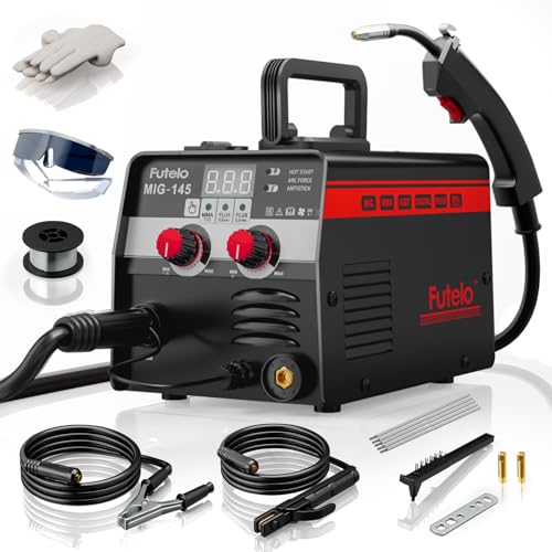
【3-IN-1 WELDER】Compact 3 in 1 welder combines MIG welder, Stick, and Lift TIG welding machine functions to tackle a wide range of welding tasks. With 30–145A output and support for carbon and stainless steel (1–5mm), it’s ideal for home DIY, repairs, and outdoor metal work. (NOTE: TIG torch not included—please purchase separately)
Step-by-Step Guide to Flux Core Welding a Basic Joint
The steps below describe a practice T-joint on known mild steel. They are not a substitute for a qualified WPS, code requirements, manufacturer instructions, or hands-on training.
Warning: Do not practice on a fuel tank, drum, sealed container, pressurized part, unknown metal, painted or solvent-wet part, vehicle safety structure, or load-bearing component. Remove fire hazards, provide ventilation, and verify that the workpiece is safe to heat.
1. Identify the Metal and Joint
Confirm that the pieces are weldable mild steel and thick enough for the selected wire and machine. Check the drawing or procedure for joint size, fit-up, weld length, and required fillet size. Do not assume that every trailer, frame, or machine part is plain carbon steel.
2. Clean the Joint
Remove oil, grease, moisture, paint, plating, heavy rust, and mill contamination from the weld area. Clean enough surrounding metal to place the work clamp on bare steel. Flux can help with normal oxides, but it cannot make an oily or coated joint safe or sound.
3. Fit and Clamp the T-Joint
Set the pieces to the required angle and clamp them so they cannot move. Use tack welds that are sound and placed where they will not interfere with the final bead. Recheck squareness after tacking because weld shrinkage can pull the parts out of position.
4. Load the Correct Wire
Install the drive roll, liner, and contact tip for the wire diameter. Feed the wire with only enough drive-roll pressure to prevent slipping. Keep the wire clean and dry, and clip off a damaged end before feeding it through the gun.
5. Set Polarity, Gas, Voltage, and Wire-Feed Speed
Use the polarity and gas listed on the wire label. Many E71T-11 self-shielded wires use DCEN; most gas-shielded E71T-1 wires use DCEP. Start with the machine chart or wire data sheet for the actual thickness and position. Wire-feed speed is measured in inches per minute or meters per minute; amperage is the resulting welding current, not the unit for wire-feed speed.
6. Set Stickout and Gun Angle
For many self-shielded wires, a stickout around 1/2 to 3/4 inch and a 10- to 20-degree drag angle are common starting points, but exact recommendations vary by wire. Hold the gun so both members of the T-joint receive heat. With slag-producing wire, use a drag technique rather than pushing the puddle.
7. Run a Test Bead on Scrap
Use scrap of the same material and thickness. Listen for a steady arc, watch the bead tie into both sides, and check for excessive spatter, worm tracks, undercut, lack of fusion, or burn-through. Adjust only within the wire manufacturer’s operating range.
8. Weld the Joint
Keep a consistent stickout, angle, and travel speed. For a small fillet, a straight stringer bead is often easier to control than a wide weave. If the procedure requires multiple passes, clean every pass completely and follow the specified bead sequence and interpass-temperature limits.
9. Clean and Inspect
Allow hot slag to cool enough to remove safely, then chip and brush it away. Look for cracks, visible porosity, incomplete fusion at the toes, undercut, overlap, incorrect bead size, and unfilled craters. A good-looking surface does not prove that a critical weld is acceptable; code work may require formal visual inspection or nondestructive testing.
Pros and Cons of Flux Core Welding
Flux core earns its place through productivity and field practicality, but it is not automatically stronger, cheaper, or easier than every alternative.
| Aspect | Advantages | Limitations |
|---|---|---|
| Productivity | Continuous wire feed and potentially high deposition rates | Slag removal and interpass cleaning add time |
| Environment | Self-shielded wire works well for many outdoor jobs | Gas-shielded FCAW still needs protection from wind |
| Material Thickness | Well suited to many medium- and heavy-section steel jobs | Often difficult on very thin sheet because of heat input and burn-through |
| Portability | FCAW-S does not need a gas cylinder | The feeder, leads, power source, and fume controls still affect portability |
| Weld Quality | Code-quality welds are possible with the correct wire, WPS, and technique | Porosity, slag inclusions, undercut, and lack of fusion can occur when setup or technique is wrong |
| Cleanup | Some wires produce easily removable slag | Fumes, spatter, and slag are generally greater than with short-circuit MIG |
For windy field repairs, self-shielded FCAW may be the practical winner. For thin sheet, clean indoor cosmetic work, or nonferrous metal, another process often gives better control.
Comparing Flux Core to Other Welding Processes
Flux Core vs. MIG
Both processes use continuous wire. Self-shielded FCAW is more convenient outdoors because it does not depend on external shielding gas. MIG usually produces less slag and smoke and is easier to clean on indoor thin-sheet work. Gas-shielded FCAW can offer strong productivity on thicker steel and out-of-position welds.
Flux Core vs. Stick
Stick welding is simple, rugged, and flexible with electrode types, but the welder must stop to replace electrodes and remove slag. FCAW keeps feeding wire and can raise productivity. Both processes can work outdoors when the correct consumable is used, and both require good technique, settings, surface preparation, and ventilation.
Flux Core vs. TIG
TIG gives precise heat and filler control and is often preferred for thin material, stainless cosmetic work, aluminum, and critical roots. It is slower and demands more coordination. FCAW is generally chosen for deposition and production rather than fine cosmetic control.
Flux Core vs. Metal-Cored Wire
Metal-cored wire is a tubular GMAW electrode with mostly metallic ingredients in the core. It normally uses external shielding gas and produces little or no slag compared with FCAW. It can be highly productive in suitable shop applications but does not replace self-shielded FCAW outdoors.
No welding process receives automatic code approval. Structural, pipeline, pressure, and transportation work may require an approved WPS, procedure qualification, welder qualification, traceable filler metal, inspection, and engineering acceptance.
Safety Considerations in Flux Core Welding
FCAW produces intense light, ultraviolet and infrared radiation, hot metal, sparks, slag, electric-shock hazards, and welding fumes. The OSHA welding hazard guidance identifies burns, eye damage, electrical shock, fire, and fume exposure as major hazards.
Control Welding Fumes
Keep your head out of the plume and use local exhaust or suitable general ventilation. The needed control depends on the wire, base metal, coatings, position, and space. Stainless steel, galvanized steel, painted metal, and plated metal can create extra hazards. OSHA’s welding fume fact sheet recommends removing coatings where possible, using ventilation, and following exposure-control requirements.
Welding galvanized steel can generate zinc oxide fume and cause metal fume fever. Drinking milk before or after welding does not replace ventilation, exposure assessment, or respiratory protection. In a workplace, respirator use must be part of a compliant respiratory-protection program that includes medical evaluation, selection, training, and fit testing where required.
Prevent Fire and Explosion
Remove combustible material from the hot-work area or protect it with suitable barriers. OSHA general-industry rules call for special precautions, including fire watchers in defined situations, when combustibles are near the work. Check both sides of walls, floors, and partitions because sparks can travel through openings. Never weld a container that held flammable or toxic material unless it has been made safe under an approved procedure.
Protect Your Eyes, Skin, and Hearing
Wear a welding helmet with the correct lens shade, safety glasses with side shields under the helmet, dry gloves, flame-resistant clothing, and leather footwear. Cover exposed skin. Hot slag can roll into cuffs, pockets, and shoes, so avoid open cuffs and synthetic clothing that can melt.
Manage Electrical and Confined-Space Hazards
Inspect leads, the gun, connectors, and the work clamp. Keep gloves and clothing dry, and do not wrap welding leads around your body. Confined-space welding needs hazard evaluation, atmospheric testing where required, ventilation, attendant or rescue provisions, and compliance with the applicable permit-space and hot-work rules. A small fan and an open door are not automatically enough.
Warning: Stop welding and move to fresh air if you develop dizziness, chest tightness, breathing trouble, nausea, fever-like symptoms, or unusual irritation. Seek medical help for severe or persistent symptoms and report the materials and coatings involved.
Tips for Machine Settings and Joint Preparation
Generic settings such as “18–20 volts for 1/4-inch steel” can be misleading because wire classification, diameter, shielding gas, position, joint design, stickout, and machine calibration all change the usable range. Start with the machine chart or wire data sheet, then test on matching scrap.
- Voltage: Influences arc length and bead shape. Too little can create a narrow, convex bead or unstable arc; too much can increase spatter, undercut, and arc instability.
- Wire-feed speed: Strongly affects current and deposition. Too low or too high for the voltage can cause an unstable arc, stubbing, excessive spatter, or poor fusion.
- Stickout: FCAW often uses a longer stickout than short-circuit MIG. Excessive or inconsistent stickout changes current and heat at the joint.
- Travel speed: Too fast can reduce bead size and fusion; too slow can create excessive buildup, slag problems, or burn-through.
- Gun angle: Use the drag angle recommended for the wire. Excessive angle can reduce shielding effectiveness and trap slag.
For thick butt joints, the drawing or WPS may call for a bevel, root face, root opening, backing, or a specific pass sequence. A blanket “45-degree bevel and 1/16-inch gap” is not correct for every joint. Fit-up must follow the design.
Vertical-up welding is often used when strength and sidewall fusion are important, but settings and technique depend on the wire. Reduce settings only when the data sheet or WPS supports the change. Vertical-down capability is classification- and procedure-specific.
Common Mistakes and How to Fix Them
Porosity
Likely causes: Oil, moisture, paint, excessive wind on FCAW-G, gas leaks, wrong gas, excessive stickout, damaged wire, or poor gun position.
Fix: Remove the defective metal as required, clean the joint, verify gas and flow for FCAW-G, shield the area from drafts, inspect the gun, and return to the recommended parameter range.
Slag Inclusions
Likely causes: Slag left between passes, a bead shape that traps slag, poor sidewall fusion, low heat input, wrong angle, or an overly wide weave.
Fix: Grind out the defect, clean every pass, use a controlled drag angle, keep the puddle visible, and use stringers or a weave width allowed by the procedure.
Burn-Through
Likely causes: Material is too thin, heat input is too high, the joint gap is too large, or travel is too slow.
Fix: Use a smaller approved wire, lower settings within the manufacturer’s range, shorten arc time with a controlled stitch sequence when appropriate, add approved backing, or switch to a process better suited to thin sheet.
Undercut
Likely causes: Excess voltage, fast travel, wrong angle, a long arc, or failure to pause at the toes.
Fix: Correct the settings, reduce excessive travel speed, improve gun angle, and make sure the bead fills both toes without overlap.
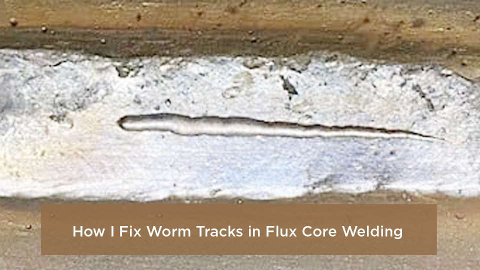
Worm Tracks
Likely causes: Gas escaping through solidifying slag, excessive voltage, or surface contamination. Some self-shielded wires are more sensitive to this appearance.
Fix: Clean the joint, reduce voltage within the data-sheet range, maintain the recommended stickout, and test on scrap.
Erratic Wire Feeding
Likely causes: Wrong drive roll, too much or too little drive pressure, a worn tip, kinked liner, birdnesting, rusty wire, or a restricted gun cable.
Fix: Match the drive system to the wire, straighten the gun cable, replace worn parts, and store wire dry. Do not overtighten the drive rolls to force damaged wire through the gun.
Real-World Examples from US Welding Practices
In structural fabrication, FCAW may be used for shop welds, field connections, stiffeners, moment connections, and repair work when the project WPS and AWS code requirements permit it. The latest AWS D1.1 edition and amendment should be checked against the contract documents rather than assumed from an old shop chart.
In heavy-equipment work, FCAW is useful for carbon-steel brackets, frames, and wear-related repair when cracks are fully removed and the base metal, preheat, filler metal, and weld sequence are known. A loader bucket or excavator component may use abrasion-resistant or high-strength steel that needs a specific procedure.
For a backyard smoker or noncritical fabrication project, flux core can join clean mild-steel plate efficiently. Coatings, unknown drums, and sealed vessels remain unsafe. A used container should never be treated as safe simply because it looks empty.
Pipeline standards such as API 1104 allow several welding processes, including FCAW, but production welding still depends on qualified procedures and personnel. Students may learn FCAW early because continuous wire feed makes arc starts and bead placement easier to practice, yet code-quality work still requires formal training, testing, and inspection.
Advanced Techniques for Better Welds
Control Weave Width
A small weave can help place metal across a wider joint, but a wide, slow weave can trap slag and raise heat input. Use stringer beads unless the wire data sheet or WPS permits a weave, and pause only enough at the sides to achieve fusion.
Manage Vertical and Overhead Welds
Choose a wire classified for the position. Keep the puddle small, use the specified stickout, and stay within the vertical or overhead parameter range. Overhead FCAW creates falling slag and spatter, so full protective clothing and controlled body position are especially important.
Plan Multi-Pass Welds
Remove all slag and inspect each pass before adding the next. Follow the required root, fill, and cap sequence. Monitor preheat and interpass temperature when the procedure calls for it. Do not use “hot and fast” as a universal root-pass rule; heat input and travel speed must fit the joint and procedure.
Control Hydrogen and Wire Storage
Store flux-cored wire in a clean, dry area and follow the manufacturer’s exposure and reconditioning instructions. Moisture, rust, and contamination can harm feeding and weld quality. Low-hydrogen designators do not excuse poor storage or wet joint surfaces.
Match Filler Metal to the Job
Match the full wire classification to the base metal, required strength, toughness, service temperature, shielding gas, position, and code. A 70-ksi classification may be common for mild-steel work, but strength matching alone does not prove suitability for fatigue, impact, corrosion, heat, or pressure service.
Conclusion: When Flux Core Welding Makes Sense
Flux core welding is a practical choice for structural steel, heavy fabrication, equipment repair, field erection, shipbuilding, and many medium-to-thick carbon-steel projects. Self-shielded wire adds outdoor portability, while gas-shielded wire supports productive shop welding. The process is less attractive for very thin sheet, aluminum, clean cosmetic work, or any job where the material and procedure are unknown.
The reliable approach is simple: identify the base metal, choose the complete wire classification, follow the manufacturer’s data sheet or approved WPS, prepare the joint, test on matching scrap, clean every pass, and inspect the finished weld. Never trade ventilation, fire prevention, or code compliance for speed.
Frequently Asked Questions
Is flux core welding good for beginners?
Yes, it can be a good process for learning wire control and fillet welds on mild steel. Continuous wire feed removes the need to restart after every stick electrode. Beginners still need instruction on polarity, machine settings, joint preparation, slag removal, ventilation, and inspection before working on load-bearing parts.
Can you use flux core welding on thin metal?
It is possible with a suitable small wire, machine, fit-up, and technique, but burn-through and distortion become harder to control as sheet gets thinner. MIG or TIG is often a better choice for automotive body panels and light tubing. Follow the machine and wire manufacturer’s minimum-thickness guidance.
What is the difference between self-shielded and gas-shielded flux core?
Self-shielded FCAW uses ingredients inside the wire to provide the shielding system and does not need an external gas cylinder. Gas-shielded FCAW uses both flux-cored wire and the gas specified for that wire. Self-shielded wire is convenient outdoors; gas-shielded wire is common in controlled shop conditions.
Does flux core welding produce strong welds?
It can produce code-quality welds when the wire, base metal, joint, settings, position, procedure, and welder qualification are correct. Strength cannot be judged from the process name or bead appearance alone. Critical work may require procedure qualification, inspection, and nondestructive testing.
How do I reduce spatter in flux core welding?
Confirm the correct polarity, voltage, wire-feed speed, stickout, drive-roll tension, gun angle, and shielding gas. Clean the metal and keep a steady drag technique. Anti-spatter products can make cleanup easier, but they do not fix an unstable arc or poor fusion.
Can flux core weld galvanized steel?
Some wires can weld galvanized steel, but heating zinc creates hazardous fume and the coating can contribute to porosity. Remove coating near the joint where permitted, provide effective ventilation or extraction, follow the wire data sheet, and restore corrosion protection after the weld. Milk is not a safety control.
Can you weld cast iron or aluminum with ordinary flux core wire?
Ordinary carbon-steel flux-cored wire is not a general-purpose solution for cast iron or aluminum. Cast iron usually needs a material-specific repair method and filler metal. Aluminum is normally welded with suitable MIG or TIG equipment and aluminum filler wire.
Sources
- American Welding Society: Flux Cored Arc Welding—Principles, Applications, and Common Challenges — FCAW definition, shielding types, applications, and common defects
- AWS A5.20/A5.20M:2025 — carbon-steel flux-cored electrode classifications and intended uses
- Miller: Flux-Cored Welding Basics for Mild Steel — basic setup, drag technique, and operating guidance
- Hobart Brothers: Self-Shielded Flux Core Wire — stickout, drag angle, storage, and field-use guidance
- OSHA: Welding, Cutting, and Brazing Hazards and Solutions — fume, radiation, burn, shock, and fire hazards
- OSHA: Controlling Hazardous Fume and Gases During Welding — ventilation, coating removal, respiratory protection, and exposure controls