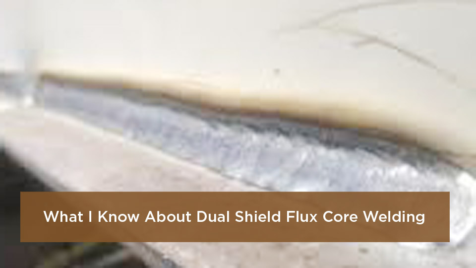
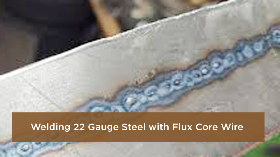
Worm tracks in a flux core weld usually show up as narrow grooves or trails after you remove the slag. The most common cause is excessive voltage for the selected wire feed speed, although damp wire, incorrect electrode extension, poor shielding, and contamination can also contribute. The safest fix is to stop, identify the cause, remove any unacceptable discontinuity, and test the corrected settings on scrap before rewelding the joint.
Quick Answer
To fix worm tracks in flux core welding, first compare your settings with the wire manufacturer’s data sheet. Reduce excessive voltage in small steps, confirm the correct wire feed speed, polarity, stickout, and travel angle, keep the wire dry, and clean the joint. Grind out unacceptable defects before rewelding.
Worm tracking can occur with both self-shielded and gas-shielded flux core welding. It is different from ordinary spatter and may appear alongside porosity, so you should not judge the weld by appearance alone when the joint carries a structural, lifting, pressure, suspension, or safety-critical load.
Key Takeaways
- Excessive voltage for the selected wire feed speed is the first setting to check.
- Use the exact polarity, shielding gas, flow range, and electrode extension listed for your wire.
- Store flux-cored wire dry, and do not rebake a spool unless its manufacturer gives a specific approved procedure.
- Clean the joint, control drafts, and use a drag technique with a stable travel angle.
- Remove unacceptable discontinuities and qualify the repair under the governing code or welding procedure when the weld is critical.
At a Glance
| Time Required | About 15 to 45 minutes for diagnosis and a small repair; longer if inspection or major defect removal is required |
| Difficulty | Intermediate; safety-critical repairs require a qualified welder or inspector |
| Tools Needed | PPE, chipping hammer, wire brush, grinder, scrap coupon, wire data sheet, and a gas leak-check solution and flowmeter for gas-shielded FCAW |
| Cost | Usually low if you already own the tools; replacement wire, gas, or professional inspection can add cost |
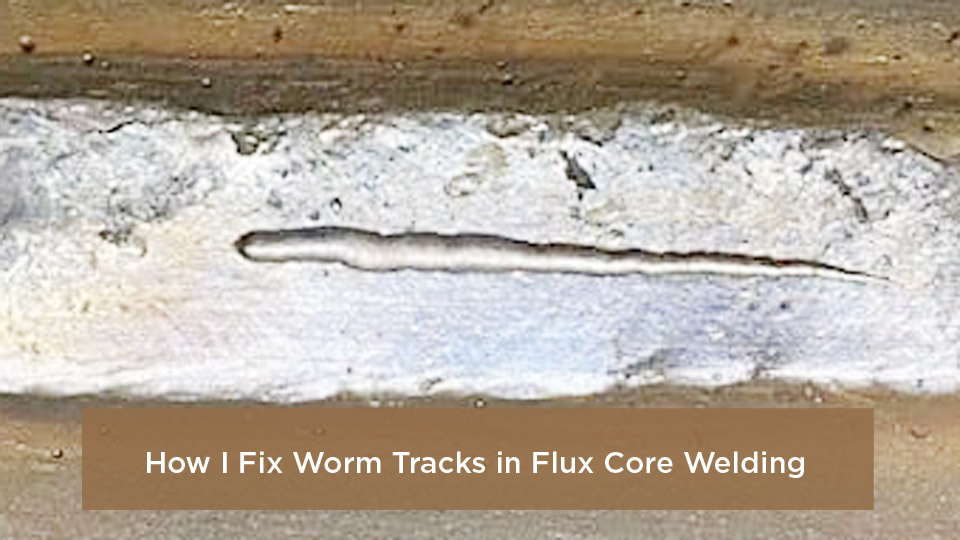
Image by Hobart Brothers
What Are Worm Tracks in Flux Core Welding?
Worm tracks, also called gas marks or worm tracking, are narrow lines or grooves that appear on the weld face after the slag is removed. They form when gas produced by the flux does not escape cleanly before the molten slag and weld pool solidify.
The marks may be shallow surface features, or they may appear with porosity. That distinction matters. A visible line does not tell you how deep the discontinuity extends, and a smooth bead does not prove that the weld is sound.
Lincoln Electric and Hobart Brothers both identify excessive voltage as a leading cause. Moisture in the wire can also contribute.
Note: Worm tracking is not the same as slag inclusion, undercut, or ordinary round porosity. Several defects can appear together, so remove all slag and inspect the complete bead before changing settings.
Common Causes of Worm Tracks in Flux Core Welds
Start with the most likely cause, then work through the setup in a fixed order. Changing several variables at once makes it difficult to identify what solved the problem.
Excessive Voltage for the Wire Feed Speed
Too much voltage lengthens the arc and can make gas marks more likely. For self-shielded FCAW, Hobart recommends returning to the manufacturer’s parameter range and reducing voltage in approximately 0.5-volt steps until the tracks disappear.
Do not assume that one voltage and wire feed speed will work for every E71T wire. The correct range depends on the exact product, wire diameter, welding position, joint, contact-tip-to-work distance, and power source.
The most reliable starting point is the data sheet for the exact spool in your feeder, not a generic settings chart.
Moisture or Damage in the Wire
Flux-cored wire can absorb moisture when it is left exposed. Moisture may increase hydrogen pickup and can contribute to worm tracks, pockmarks, or porosity. Keep the wire in its original bag and box in a dry, enclosed area when it is not in use.
Inspect exposed layers for rust, white residue, physical damage, or contamination. Remove only the damaged outer layers if the manufacturer’s guidance allows it. Replace suspect wire when a clean test spool solves the problem.
Warning: Do not put a spool of tubular wire in an oven unless the wire manufacturer provides a specific reconditioning procedure. Heat can damage spool materials and affect lubricants used for feeding and arc stability.
Incorrect Polarity or Electrode Extension
Check polarity before touching the voltage control. Many self-shielded wires run on DC electrode negative, while many gas-shielded wires run on DC electrode positive, but the label and data sheet for your exact wire take priority.
Electrode extension, often called stickout, also affects current, preheating of the wire, and arc behavior. A general starting point for many flux-cored wires is about 3/4 inch, but some T-8 products call for a longer range. Follow the wire manufacturer’s contact-tip-to-work-distance or stickout recommendation.
Dirty Base Metal or Contaminated Joint
Oil, grease, paint, moisture, heavy rust, mill scale, cutting residue, and coatings can create gas or interfere with fusion. Clean the weld area to the level required by your filler metal and welding procedure. Pay close attention to the root, groove faces, and areas where slag can become trapped between passes.
Use a cleaner that is approved for the material and welding environment, follow its safety data sheet, and allow it to evaporate fully before striking an arc.
Warning: Never weld where vapors from chlorinated brake cleaner or other chlorinated degreasers can reach the arc. OSHA requires chlorinated-hydrocarbon cleaning operations to be separated from welding atmospheres.
Shielding Gas Problems on Dual-Shield Wire
Gas-shielded FCAW can develop porosity or related surface marks when a draft disrupts the shielding gas, a hose leaks, the nozzle is blocked, or the flow is outside the wire manufacturer’s range. Confirm the required gas composition first. Some wires are designed for 100% CO2, while others require a specific argon and CO2 blend.
Do not treat a higher flow rate as a cure for wind. Excess flow can create turbulence and draw room air into the shielding envelope. Block drafts, repair leaks, clean the nozzle, and stop gas-shielded welding when conditions cannot be controlled.
Travel Angle, Speed, and Puddle Control
Flux-cored welding normally uses a drag technique. A travel angle of about 5 to 15 degrees is a common starting range, although the joint and position can change the best angle. Extreme angles can destabilize the arc, reduce penetration, or trap slag.
Travel speed must keep the arc on the leading or trailing edge recommended by the procedure without letting the puddle outrun the arc. Moving too fast can leave poor tie-in, while moving too slowly can create an oversized, overly fluid puddle.
How to Diagnose Worm Tracks Correctly
Diagnosis starts after the slag is removed. Use good lighting and examine the whole bead, including starts, stops, toes, and tie-ins. Compare what you see with a known-good test bead made with the same wire and position.
| What You See | Likely Check | First Action |
|---|---|---|
| Long, shallow trails under the slag | Voltage too high; damp wire | Check the data sheet and reduce voltage in small steps |
| Round surface holes or scattered pores | Contamination or shielding loss | Clean the joint and inspect the gas system |
| Dark lines between passes | Slag inclusion or poor interpass cleaning | Remove slag fully and correct bead placement |
| Groove along a weld toe | Undercut, not worm tracking | Correct voltage, speed, and gun angle |
Liquid penetrant testing can reveal some surface-breaking discontinuities when it is performed with the correct procedure, but it does not reveal hidden internal porosity. Radiographic or ultrasonic examination requires trained personnel, approved procedures, and acceptance criteria from the governing code or specification.
Pro Tip: Record the wire brand, classification, diameter, lot, polarity, voltage, wire feed speed, gas, flow, position, and electrode extension before making changes. A simple log makes repeated defects much easier to isolate.
Step-by-Step Guide to Fixing Worm Tracks
Step 1: Decide Whether the Weld Is Safety-Critical
Stop and identify the service of the part. A decorative bracket and a vehicle suspension mount do not have the same acceptance requirements. Structural steel, pressure equipment, lifting devices, trailers, frames, and other critical parts may require a qualified repair procedure and inspection.
Step 2: Remove Slag and Expose the Full Discontinuity
Let the weld cool as required by the procedure, then remove slag with a chipping hammer and wire brush. Inspect the entire length. Mark every visible track, pore, crack, undercut area, or questionable tie-in.
Step 3: Remove Unacceptable Weld Metal
Use a grinder, carbide burr, or approved gouging method to remove the discontinuity until you reach clean, sound metal. Feather the ends of the repair so the new weld can tie in smoothly. There is no universal maximum grinding depth. Stop before you reduce the base metal or remaining weld below the design requirement.
Step 4: Check the Wire and Joint
Confirm the wire classification, diameter, polarity, and storage condition. Replace visibly rusted or suspect wire when needed. Clean the joint with mechanical methods and an approved residue-free cleaner, then allow it to dry completely.
Step 5: Return the Machine to the Manufacturer’s Range
Use the parameter chart for the exact wire and diameter. If worm tracks appeared while you were inside that range, reduce voltage in small increments while keeping wire feed speed within the approved operating window. Verify the work lead connection, drive-roll setup, liner, contact tip, and wire feeding.
Step 6: Verify Shielding and Technique
For gas-shielded wire, confirm the specified gas, leak-free connections, clean nozzle, and recommended flow. Shield the work from drafts. Set the recommended electrode extension and use a steady drag angle. Avoid an oversized weave unless the procedure permits it.
Step 7: Test on Scrap Before Rewelding
Make a test bead on clean scrap of similar thickness and in the same position. Remove the slag and inspect it. Change only one variable at a time. When the test bead is clean and the bead profile is acceptable, apply the same setup to the repair.
Step 8: Reweld and Inspect
Reweld the prepared area according to the approved procedure. Clean between passes, fill starts and stops, and inspect after the final slag removal. Escalate the weld for qualified inspection when the service, code, customer specification, or defect history requires it.
Machine Settings That Help Prevent Worm Tracks
Generic settings tables can be misleading because two wires with similar AWS classifications may have different operating windows. Use this order instead:
- Wire data sheet: Confirm classification, diameter, polarity, shielding gas, flow range, and position.
- Power-source chart: Choose a starting voltage and wire feed speed for the material thickness.
- Test coupon: Fine-tune within the approved range.
- Small voltage correction: If worm tracking appears, reduce voltage gradually before making unrelated changes.
- Document the result: Save the final settings for that wire, joint, and position.
Miller’s flux-cored welding guide also recommends using the machine chart as a starting point and fine-tuning with test welds.
Products Worth Considering

E71T-GS FLUX CORE WIRE: This self-shielding, AWS E71T-GS flux-cored wire excels due to its advanced core design, delivering exceptional arc stabilization and high feedability for effortless welding. The core also incorporates powerful deoxidizing agents, ensuring clean, reliable welds even when welding through light rust or mill scale.

GASLESS: E71T-11 does not require a shielding gas. The flux core inside the wire acts in place of the shielding gas. This makes the wire very versatile and perfect for mobile jobs, outdoor jobs, and people who do not have access to shielding gas.
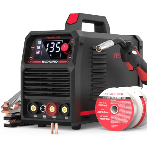
READY OUT OF THE BOX: Start welding immediately! It masterfully handles Gasless Flux Core MIG, Stick, and Lift TIG (Extra Lift TIG torch required). This budget-friendly 3-in-1 machine includes extra E71T-GS .030''&.035'' flux core wires, known for its smooth arc and high feedability. Say goodbye to heavy shielding gas cylinders—perfect for outdoor, windy, or all-position welding.
Joint Prep and Technique Tips for Cleaner Flux Core Beads
- Remove contamination: Clean oil, paint, moisture, heavy scale, and cutting residue from the joint area.
- Prepare the joint to the drawing or WPS: Bevel angle, root opening, and land are design variables, not universal numbers.
- Drag the gun: Keep a stable 5-to-15-degree travel angle unless the wire procedure calls for something different.
- Control electrode extension: Use the wire manufacturer’s value and check it throughout the pass.
- Clean every pass: Remove slag from toes, valleys, starts, and stops before depositing the next bead.
- Keep the arc visible: Position your head and gun so you can see the puddle edge without placing your face in the fume plume.
Warning: Welding fumes and gases can harm your health. Use effective local exhaust or general ventilation, keep your head out of the plume, and follow the filler-metal safety data sheet. A particulate filter such as P100 does not protect against every gas or vapor. Respirator selection must match the measured hazards and workplace respiratory-protection requirements.
Self-Shielded vs. Gas-Shielded Flux Core
Both processes can produce worm tracks. The better choice depends on the wire, environment, joint, and required mechanical properties.
| Aspect | Self-Shielded FCAW | Gas-Shielded FCAW |
|---|---|---|
| External gas | Not required | Required and wire-specific |
| Outdoor use | More tolerant of air movement, but not immune to poor conditions | Drafts can disrupt shielding |
| Typical setup risk | Wrong polarity, voltage, or electrode extension | Wrong gas, leaks, drafts, flow, voltage, or extension |
| Wire storage | Keep dry and enclosed | Keep dry and enclosed |
| Best choice | Field work when the selected wire meets the job requirements | Controlled shop work and procedures that specify gas-shielded FCAW |
Do not switch between self-shielded wire, gas-shielded wire, solid wire, gas mixtures, or polarity as an improvised repair. A change in process or consumable can change weld-metal properties and may require a revised or requalified welding procedure.
Products Worth Considering

E71T-GS FLUX CORE WIRE: This self-shielding, AWS E71T-GS flux-cored wire excels due to its advanced core design, delivering exceptional arc stabilization and high feedability for effortless welding. The core also incorporates powerful deoxidizing agents, ensuring clean, reliable welds even when welding through light rust or mill scale.

Welding Easy and Quick: AWS E71T-GS 030” Flux Core welding wire (The actual Net Weight of Wire is 2LB), no need for shielding gas, install it then you can welding all positions, single and multi pass welding. Great for T-joints, butt welds & lap welds.

E71T-GS FLUX CORE WIRE: This self-shielding, AWS E71T-GS flux-cored wire excels due to its advanced core design, delivering exceptional arc stabilization and high feedability for effortless welding. The core also incorporates powerful deoxidizing agents, ensuring clean, reliable welds even when welding through light rust or mill scale.
Common Flux Core Mistakes and How to Avoid Them
Using MIG Habits Without Checking the Wire
A short MIG-style stickout, the wrong polarity, or a push technique can make flux core unstable. Read the spool label and set the machine for that wire before welding.
Turning Up Voltage to Travel Faster
More voltage is not automatically more productive. Excess voltage is a known cause of worm tracking. Increase deposition only within the wire’s approved parameter range and the WPS.
Leaving Wire Exposed in a Damp Shop
Return unused wire to its original bag and box or protect it with the manufacturer’s recommended storage method. Do not assume a new spool is usable if the packaging is damaged or the wire shows corrosion.
Welding Over Rust, Paint, or Cutting Residue
Flux can tolerate some surface condition variation, but it is not a substitute for proper preparation. Clean the joint and remove coatings safely before you weld.
Trying to Beat Wind with More Gas
High flow does not make gas-shielded FCAW windproof. Shield the joint, eliminate drafts, or use a properly qualified self-shielded procedure when the job allows it.
Advanced Tips for Difficult or Code Work
When worm tracks keep returning, compare the problem across controlled test coupons. Try a sealed spool of the same product, verify calibration of the wire feeder and voltage display, check contact-tip wear, inspect the liner and drive rolls, and confirm that the work lead has a clean, secure connection.
For vertical-up welding, follow the position-specific parameter range and technique published for the exact wire. Do not automatically increase wire feed speed or use a fixed weave pattern. T-8 and gas-shielded all-position wires can have narrow operating windows.
Preheat is a base-metal, thickness, restraint, hydrogen-control, and code decision. Do not apply a generic 150°F preheat or strike an arc in open air to “dry” the wire tip. Use the preheat and interpass temperatures in the WPS or an engineering-approved procedure.
For code work, record the consumable trade name and classification, lot number, storage history, machine settings, gas, joint, position, repairs, and inspection results. Do not replace flux-cored wire with ER70S-6 solid wire or change shielding gas unless the applicable procedure permits the change.
Conclusion: Fix Worm Tracks at the Cause
The fastest dependable fix is to return to the exact wire manufacturer’s recommendations and correct one variable at a time. Start with excessive voltage, then verify polarity, wire feed speed, electrode extension, storage, joint cleanliness, gas coverage, and technique.
Do not hide the symptom with another pass. Remove any unacceptable discontinuity, test the corrected setup on scrap, and reweld only after the bead runs clean. When the weld carries a critical load or falls under a code, let the approved procedure and qualified inspection determine whether the repair is acceptable.
Frequently Asked Questions
What causes worm tracks in vertical flux core welding?
Vertical welding can expose problems with voltage, electrode extension, bead placement, and puddle control, but gravity alone is not a complete diagnosis. Check the position-specific range for your exact wire, confirm the drag angle and stickout, and reduce excessive voltage in small steps.
Can you weld over worm tracks without grinding?
Do not assume another pass will remove the problem. For a repair, remove any discontinuity that is unacceptable under the drawing, WPS, code, or inspector’s direction, then reweld sound metal. Safety-critical work may require qualified inspection before and after repair.
What is the best gas mix for preventing worm tracks in dual-shield FCAW?
There is no universal best mix. Use the shielding gas listed on the data sheet for the exact wire. Depending on the product, that may be 100% CO2 or a specified argon and CO2 blend. Changing gas can alter arc behavior, mechanical properties, and procedure qualification.
How can you tell whether the flux core wire is causing the tracks?
Inspect the wire and packaging for moisture exposure, rust, white residue, or damage. Compare the result with a sealed spool of the same product while holding the machine settings and technique constant. Do not rebake the spool unless the manufacturer publishes an approved procedure.
Are worm tracks the same as porosity?
They are related gas-caused discontinuities, but they do not always look the same. Worm tracks appear as elongated surface marks under the slag, while porosity commonly appears as rounded cavities and may be internal or surface-breaking. Both require evaluation against the applicable acceptance criteria.
Should you increase wire feed speed when worm tracks appear?
Not automatically. Wire feed speed changes current and deposition rate. First confirm that both voltage and wire feed speed are inside the manufacturer’s range. Because excessive voltage is a common cause, a small voltage reduction is usually the cleaner first test.
Sources
- Lincoln Electric: Gas Marks on FCAW Process Welds — causes and corrective actions for gas marks and worm tracks
- Hobart Brothers: Troubleshooting Common Self-Shielded FCAW Problems — voltage, porosity, worm tracking, angles, and parameter guidance
- Hobart Brothers: Best Practices for Handling and Storing Filler Metal — dry storage and cautions against rebaking spooled wire
- Miller: Flux-Cored Welding Basics for Mild Steel — stickout, machine charts, drag technique, and travel angle
- OSHA 29 CFR 1910.252 — welding ventilation, PPE, and chlorinated cleaning-compound precautions
- NIOSH: Welding Fumes and Manganese — welding-fume exposure and health guidance