
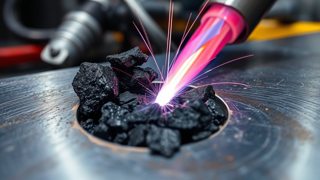
Slag inclusion can hide inside a clean-looking flux core weld and interrupt the solid weld metal that carries the load. It forms when slag, oxides, or other non-metallic material becomes trapped during solidification instead of rising to the surface. Poor interpass cleaning is a major cause, but joint shape, bead placement, travel speed, heat input, and wire-specific gun technique also affect the risk.
Quick Answer
Slag inclusion in flux core welding occurs when hardened flux residue or another non-metallic material becomes trapped inside the weld. Prevent it by following the wire manufacturer’s settings, preparing an accessible joint, controlling the puddle with the correct angle and speed, and completely cleaning every pass before depositing the next bead.
Key Takeaways
- The slag layer on top of a flux core weld is normal; slag trapped inside the weld metal is an inclusion.
- Old slag, poor bead placement, restricted joint access, incorrect angles, and unsuitable parameters are common causes.
- There is no single correct gun angle for every flux-cored wire, position, and joint. Follow the wire data sheet or qualified welding procedure.
- Remove slag from the bead face, toes, craters, and crevices before every additional pass.
- A visual check can find surface indications but cannot prove that the weld is free of internal inclusions.
- A confirmed inclusion should be removed to sound metal, re-welded under the required procedure, and inspected again.
At a Glance
| Time Required | A few minutes for preparation and cleaning between passes; repair time depends on the depth and length of the inclusion. |
| Difficulty | Beginner to intermediate for prevention; qualified personnel may be required for structural repair and inspection. |
| Tools Needed | Welding PPE, chipping hammer, suitable wire brush, grinder as needed, adequate lighting, wire data sheet, and inspection tools required by the project. |
| Cost | Usually low when cleanup tools and PPE are already available; professional repair or nondestructive testing can add significant cost. |
What Is Slag Inclusion in Flux Core Welding?
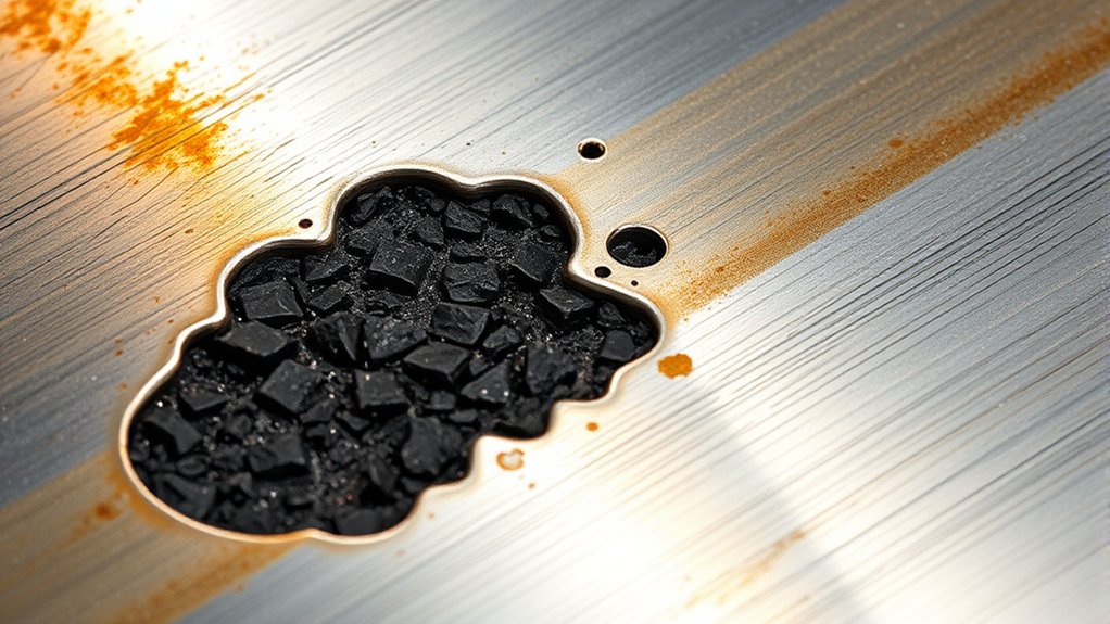
Flux-cored arc welding uses a tubular electrode containing flux. As the wire melts, the core ingredients help shield and refine the weld pool and produce a slag layer over the completed bead. This surface layer is a normal part of both self-shielded and gas-shielded flux-cored welding and is described in the Lincoln Electric FCAW overview.
A slag inclusion forms when part of that non-metallic material remains inside the solidifying weld metal or becomes trapped between adjacent weld passes. The inclusion may appear at the weld toe, between beads, near the root, or deeper inside the joint. The TWI slag-inclusion guide identifies joint geometry, bead profile, welding technique, and incomplete interpass cleaning as major factors.
Dirty base metal can make the overall weld problem worse. Rust, oil, paint, heavy mill scale, moisture, and old slag may interfere with arc stability, fusion, or weld-pool behavior. Old slag is especially important because a new bead can cover it before it has a chance to escape.
Slag inclusion is a weld discontinuity that can reduce the usable cross-section of the weld and interrupt metallic continuity. Whether a particular indication is a rejectable defect depends on its size, shape, location, service conditions, and the acceptance criteria in the applicable code, drawing, specification, or welding procedure.
Note: Slag sitting on top of a cooled flux core weld is expected. It becomes an inclusion only when it is trapped within the weld metal or between weld layers.
Your technique plays a major role. Incorrect travel or work angles, excessive travel speed, poor bead placement, and unsuitable heat input can create pockets where slag becomes locked in place. Learning the basic techniques for flux core welding can help you develop better puddle control, but the instructions for the exact wire you are using should always take priority.
Top Causes of Slag Inclusion in Flux Core Welding
You need to understand the main causes of slag inclusion before you can correct it. The defect is rarely caused by one setting alone. It usually develops from a combination of joint access, bead shape, slag behavior, and welder technique.
- Slag left between passes: Welding over old slag can trap it between the previous bead and the new weld metal.
- Poor bead placement: Overlapping beads, deep valleys, rolled toes, and badly positioned root passes can create pockets that hold slag.
- Restricted joint access: A groove that is too narrow or a root that the gun cannot reach may prevent proper fusion and cleaning.
- Incorrect travel or work angle: The arc may be aimed away from the joint face while slag moves in front of the puddle.
- Excessive travel speed: Moving too fast can produce a narrow bead, poor tie-in, undercut, or slag that runs ahead of the molten metal.
- Unsuitable heat input: Settings that are too low may create a cold, convex bead, while excessive or mismatched settings can produce undercut or a bead profile that traps slag.
- Excessive weaving: A weave that is too wide can allow the center to cool, produce poor sidewall fusion, or leave slag along the toes.
- Contamination: Rust, oil, paint, moisture, scale, and dirt can affect weld quality and make sound fusion more difficult.
High welding speed is therefore not just an appearance problem. If the arc outruns the puddle or the bead does not tie into both sides of the joint, slag may remain at the root or toes.
Incorrect welding settings can also increase the risk, but simply raising the voltage is not a universal solution. Voltage, wire feed speed, electrode extension, travel speed, wire diameter, joint design, and welding position work together. Begin with the wire manufacturer’s parameter range or the project’s welding procedure specification, then make permitted adjustments on a test coupon.
Self-Shielded Versus Gas-Shielded Flux Core
Self-shielded FCAW, often marked FCAW-S, creates its shielding from ingredients inside the wire and does not use an external shielding-gas cylinder. Gas-shielded FCAW, or FCAW-G, uses both a flux-filled wire and an external shielding gas. Both processes form slag that must be removed when required.
Gas flow applies only to FCAW-G. Incorrect gas, poor coverage, wind, leaks, or unsuitable flow can contribute to shielding problems and porosity, but gas-flow adjustment is not a substitute for removing slag or correcting bead placement. Review the process-specific information in your wire data sheet and your equipment manual. Additional welding setup and gas flow troubleshooting is relevant only when your process actually uses external shielding gas.
Work Angle Versus Travel Angle
Travel angle is the forward or backward tilt of the gun along the direction of travel. Work angle is the side-to-side position of the gun across the joint. For example, a square butt joint normally places the gun near the center of the joint, while a fillet weld normally aims the gun between the two members. Confusing these two angles can direct the arc away from a sidewall or root.
Most slag-producing FCAW applications use a drag or pull technique. However, exact travel angles vary. Miller gives a general starting range of 5–15° under normal conditions. Hobart guidance for some wires uses 0–10°, while separate self-shielded troubleshooting guidance lists 15–45° in flat, horizontal, and overhead positions and 5–15° for vertical-up welding. These values are not interchangeable universal rules. Wire classification, slag system, position, joint, and manufacturer instructions determine the correct technique.
| Cause | What You May Notice | Correction |
|---|---|---|
| Old slag between passes | Dark or glassy material at a bead edge, crater, or interpass boundary | Chip, brush, or grind until the entire pass and both toes are clean. |
| Poor joint access | Slag repeatedly trapped at the root or sidewall | Correct the groove, root opening, fit-up, gun access, or bead sequence as permitted. |
| Incorrect angle | Slag runs ahead of the puddle or remains along one toe | Use the wire-specific travel angle and aim the work angle into the joint. |
| Travel speed too fast | Narrow bead, poor tie-in, undercut, or slag ahead of the arc | Reduce speed within the approved procedure and keep the arc at the correct part of the puddle. |
| Parameters too low or mismatched | Cold, convex bead with poor wetting at the toes | Return to the manufacturer or WPS range and verify wire feed, voltage, stickout, and polarity. |
| Excessive weave or poor overlap | Deep valleys between beads or incomplete sidewall tie-in | Use narrower beads, controlled overlap, and permitted pauses at the sidewalls. |
How Slag Inclusion Affects Your Welds
Slag inclusion can reduce weld strength, toughness, fatigue resistance, and service reliability by interrupting the continuous weld metal. The effect depends on the inclusion’s size, orientation, location, and the loads placed on the joint.
Linear inclusions or groups of inclusions may create local stress concentrations and reduce the effective load-carrying area. This matters most in joints exposed to cyclic loading, impact, vibration, low temperatures, pressure, or other demanding service.
Surface-breaking inclusions can also leave rough pockets, grooves, or irregular bead edges. These areas can make inspection and coating more difficult. Slag inclusion should not be described as a universal direct cause of corrosion, but an exposed defect, moisture-retaining crevice, or damaged protective coating may contribute to corrosion in a suitable environment.
Clean work is especially important for multi-pass welds. Remove slag before each new pass and inspect the bead before continuing. Surface contamination can also contribute to porosity in arc welding, although porosity and slag inclusion are different discontinuities with different formation mechanisms.
A clean-looking bead surface is not proof that the weld is free of internal slag. Prevention must happen while the joint is prepared, welded, cleaned, and inspected.
Best Practices to Prevent Slag Inclusion in Your Welds
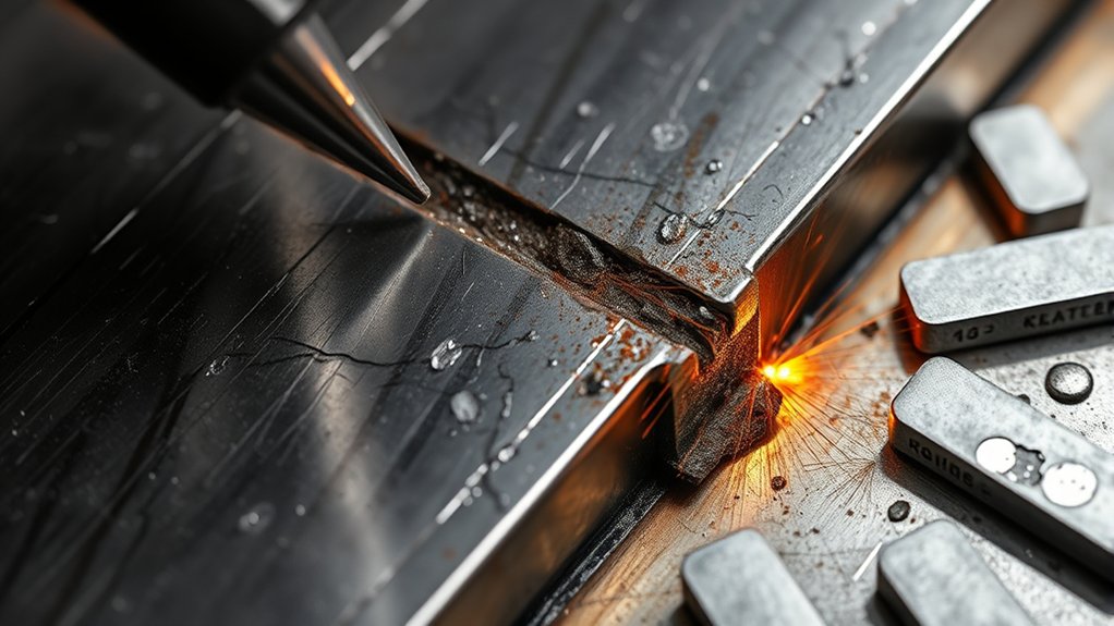
Use the following workflow before and during welding. For code-governed work, the approved WPS and project documents take priority over general guidance.
- Identify the wire and process. Confirm whether the wire is self-shielded or gas-shielded, its classification, permitted positions, polarity, electrode-extension range, shielding-gas requirements, and recommended parameters. Do not assume that two flux-cored wires use the same setup.
- Clean the joint. Remove old slag, rust, oil, moisture, dirt, paint, and heavy scale from the weld area. Clean the work-clamp location so the welding circuit has reliable contact.
- Check fit-up and access. Make sure the root opening, bevel, groove width, and gun access allow the arc to reach the root and sidewalls. A narrow groove can trap slag even when the machine settings are reasonable.
- Set the machine from approved guidance. Use the wire data sheet, welder chart, or WPS for the wire diameter, metal thickness, joint, and position. Verify polarity before welding and make permitted test welds on comparable scrap.
- Use the correct work and travel angles. Aim the work angle into the joint and use the wire-specific travel technique. A 5–15° drag angle is a common starting point, but some self-shielded products specify larger drag angles and some vertical wires call for neutral or slight-push technique.
- Control travel speed and bead placement. Keep the arc where it can fuse the joint instead of allowing the molten metal or slag to run ahead. Use bead overlap and sidewall pauses that produce a smooth profile without deep valleys or undercut.
- Clean and inspect every pass. Remove slag from the entire bead, both toes, stop-start areas, craters, and tight crevices. Do not deposit another pass until the surface is clean enough to inspect.
Warning: Do not weld over visible slag. Another pass may cover the material without removing it, leaving a hidden inclusion inside the completed joint.
Pro Tip: Watch the line between the molten puddle and the slag behind it. If slag repeatedly moves ahead of the arc or gathers at one toe, stop and correct your angle, speed, bead placement, or settings instead of trying to outrun it.
Understanding how flux core welding is used also helps you choose a suitable wire and process. A wire designed for outdoor self-shielded work may behave differently from a gas-shielded wire used for high-deposition fabrication.
| Best Practice | What You Should Do |
|---|---|
| Clean Base Metal | Remove rust, oil, moisture, dirt, paint, heavy scale, and old slag from the weld area. |
| Use the Correct Angles | Separate work angle from travel angle and follow the recommendation for the exact wire and position. |
| Set Correct Parameters | Match polarity, voltage, wire feed speed, electrode extension, and gas requirements to the wire data sheet or WPS. |
| Provide Joint Access | Use fit-up and groove dimensions that let the arc reach the root and sidewalls and allow cleaning between passes. |
| Control Bead Placement | Avoid deep valleys, rolled toes, excessive weaving, and bead sequences that form slag pockets. |
| Clean Between Passes | Remove slag from the bead face, toes, craters, and stop-start locations before adding another layer. |
How to Remove Slag After Welding
After welding, allow the bead and slag to cool enough for the cleanup method required by the procedure. Wear safety glasses under your welding helmet or face shield because hardened slag can release sharp, hot fragments when chipped.
Use a chipping hammer to break loose thick slag, then clean the bead and toes with a wire brush suited to the base material. A narrow chisel, pick, or needle scaler can help reach tight corners, but avoid gouging the base metal or reducing the required weld size.
An angle grinder may be needed for tightly trapped slag, difficult groove welds, high spots, or repair excavation. Use a suitable wheel and light pressure. Heavy grinding can remove sound weld metal, reduce the weld throat, or create grooves that collect slag during the next pass.
Keep cleanup tools in good condition. Use separate, clearly identified brushes and grinding tools for stainless steel and carbon steel to avoid transferring carbon-steel particles onto stainless surfaces.
Good slag removal improves visibility and makes surface inspection more reliable. It does not, by itself, prevent worm tracks in flux core welding. Worm tracks are a separate surface discontinuity associated with gas escaping through solidifying slag and may require checking voltage, moisture, electrode extension, storage, and wire-specific recommendations.
Warning: Slag can remain hot after the weld darkens, and chipped pieces can travel several feet. Protect your eyes, face, skin, nearby workers, windows, hoses, and combustible material.
How to Inspect a Weld for Slag Inclusion
Begin with a visual examination after the bead is fully cleaned and adequately lit. Look for exposed glassy material, linear grooves, dark pockets, irregular bead overlap, deep valleys between passes, undercut, rolled toes, and stop-start areas that were not blended or cleaned.
Inspect any area where the bead appears to sit on top of the base metal rather than blend into it. Poor sidewall fusion, excessive convexity, and undercut can create locations where slag becomes trapped. Check the entire length of the weld rather than inspecting only the easiest section to see.
Visual inspection can reveal only surface-visible conditions. A smooth bead cannot confirm that the weld is free of internal slag. When internal quality matters, the drawing, code, contract, WPS, or inspection plan may require radiographic testing, ultrasonic testing, destructive testing, or another qualified method. The American Society for Nondestructive Testing explains that radiographic testing produces images of internal component conditions.
For structural, pressure-retaining, lifting, vehicle-safety, or other critical work, use the required acceptance standard and a qualified inspector. Do not approve a weld solely because the surface looks smooth.
How to Repair Slag Inclusion
A suspected internal inclusion should not be covered with another bead. Follow the project’s repair procedure and obtain any required authorization before altering a code-governed weld.
- Locate and mark the indication. Use the inspection report, visible evidence, or qualified NDT results to identify the affected area.
- Remove the affected weld metal. Grind, machine, or gouge as permitted until the slag and unsound metal are completely removed.
- Clean and examine the excavation. Remove residue and verify that the cavity reaches sound metal and has a shape that can be re-welded without trapping more slag.
- Re-weld under the approved procedure. Use the specified consumable, polarity, parameters, preheat, interpass temperature, bead sequence, and cleaning method.
- Reinspect the repair. Perform the visual and nondestructive examinations required by the original acceptance criteria or repair plan.
Warning: Do not try to “burn out” a confirmed inclusion by depositing another pass over it. The new weld may trap the slag deeper, enlarge the repair area, or hide the indication from surface inspection.
Products Worth Considering
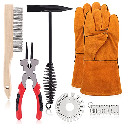
☛ 1, 【 What You Get】 ------ In this kit, You will get 7Pcs 10 Inch Scratch Wire Brush Slag Removal Tool with Welding Gloves. Including 1 piece of wire brush, 1 piece of welding hammer and 1 piece welding plier, 1 piece Metal sheet thickness gauge,1Pcs Round dual sided wire gage. In total 5Pcs. Which are easy to remove and clean corrosion and slag from most of your welds, Welding chipping hammer and steel wire brush, makes it easy to clean and remove slag from all your welds.

Package Includes: You will receive a 11-inch chipping hammer and a 10.5 inch wire brush, lightweight and practical for everyday cleaning tasks for welders and DIY enthusiasts

Dual-Function Chipi Hammer Design: Power through metalwork with precision; engineered head reaches tight spots and removes stubborn material efficiently; delivers clean professional results on every fabrication project for all skill levels
Common Mistakes That Lead to Slag Inclusion
Many slag problems begin with small habits that appear harmless. You may move too fast, skip cleaning, use a memorized angle for the wrong wire, or weld over slag because the exposed bead looks acceptable.
- Welding over rust, oil, paint, moisture, heavy scale, or old slag
- Moving the gun too fast for the weld pool and slag system
- Using too little heat or settings outside the wire manufacturer’s range
- Holding the wrong work angle or travel angle for the joint and position
- Using the wrong polarity for the selected wire
- Using excessive or inconsistent electrode extension
- Making a weave that is too wide for the joint
- Leaving deep valleys between adjacent beads
- Adding another pass before cleaning the previous pass
- Assuming a smooth surface proves that the weld is sound internally
- Changing production-weld parameters without checking the WPS or required authorization
On practice coupons, change one variable at a time so you can identify what improves the bead. On code-governed or production work, remain within the approved WPS and report recurring problems rather than making unauthorized changes.
Slag Inclusion Troubleshooting Guide
| Problem | Likely Causes | What to Check |
|---|---|---|
| Slag repeatedly appears at one toe | Incorrect work angle, poor sidewall fusion, undercut, or uneven bead placement | Aim the arc into the affected sidewall, confirm the work angle, and use the permitted sidewall pause. |
| Slag moves in front of the puddle | Travel angle, travel speed, puddle size, or wire technique is unsuitable | Return to the data-sheet angle, adjust speed within the procedure, and keep the arc on the correct portion of the puddle. |
| Slag remains in deep valleys between passes | Poor bead overlap, excessively convex beads, or an unsuitable pass sequence | Correct bead placement, clean the valleys thoroughly, and use a sequence that leaves an accessible profile. |
| Slag is difficult to remove | Wire slag system, poor bead shape, undercut, contamination, or unsuitable settings | Review the wire instructions, bead profile, toe fusion, parameters, and cleaning method. |
| Inclusion returns after repair | Incomplete excavation, residue left in the cavity, poor repair geometry, or unchanged technique | Remove the defect to sound metal, clean the excavation, correct the root cause, and reinspect. |
| Surface shows worm-like lines | Possible worm tracking rather than slag inclusion | Check voltage, moisture, wire storage, stickout, and the consumable manufacturer’s troubleshooting guidance. |
Products Worth Considering

E71T-GS FLUX CORE WIRE: This self-shielding, AWS E71T-GS flux-cored wire excels due to its advanced core design, delivering exceptional arc stabilization and high feedability for effortless welding. The core also incorporates powerful deoxidizing agents, ensuring clean, reliable welds even when welding through light rust or mill scale.

E71T-GS FLUX CORE WIRE: This self-shielding, AWS E71T-GS flux-cored wire excels due to its advanced core design, delivering exceptional arc stabilization and high feedability for effortless welding. The core also incorporates powerful deoxidizing agents, ensuring clean, reliable welds even when welding through light rust or mill scale.

E71T-GS FLUX CORE WIRE: This self-shielding, AWS E71T-GS flux-cored wire excels due to its advanced core design, delivering exceptional arc stabilization and high feedability for effortless welding. The core also incorporates powerful deoxidizing agents, ensuring clean, reliable welds even when welding through light rust or mill scale.
Frequently Asked Questions
Can slag inclusion affect the strength of the weld?
Yes. Slag inclusion interrupts the continuous weld metal and can reduce the joint’s effective load-carrying area, toughness, fatigue resistance, or reliability. The actual effect depends on the inclusion’s size, shape, orientation, location, service loads, and applicable acceptance standard.
What materials are most prone to slag inclusion?
Slag inclusion is linked more closely to slag-producing welding processes, joint design, consumable behavior, and technique than to one base metal. Carbon steel, low-alloy steel, and stainless steel welds can all develop inclusions when slag is trapped or interpass cleaning is incomplete.
How can I visually identify slag inclusion?
After cleaning the weld, look for exposed glassy material, dark linear pockets, grooves, irregular bead overlap, deep valleys, rolled toes, or suspicious stop-start areas. These signs can reveal surface-breaking conditions, but visual inspection cannot confirm that the weld is free of internal slag.
Is slag inclusion more common in certain welding positions?
Vertical and overhead positions can make puddle and slag control more difficult because gravity affects the molten metal. However, a suitable positional wire, correct parameters, proper angle, controlled bead placement, and complete interpass cleaning can reduce the risk.
What are the long-term effects of slag inclusion on welds?
An inclusion may reduce fatigue life, toughness, or service reliability when the joint is highly loaded or exposed to vibration, impact, pressure, or low temperatures. The effect is not identical in every weld, which is why the governing acceptance criteria and service conditions matter.
Can I weld over slag to burn it out?
No. Depositing another pass may cover the slag without removing it and can trap the material deeper inside the joint. Remove visible slag before the next pass, and excavate a confirmed inclusion to sound metal before re-welding.
Will increasing voltage always stop slag inclusion?
No. Low heat input can contribute to a cold, convex bead, but excessive or mismatched voltage, current, wire feed speed, travel speed, or electrode extension can also produce a bead shape that traps slag. Use the wire manufacturer’s range or the approved WPS instead of changing one setting without considering the others.
Which inspection method can find internal slag inclusion?
Radiographic testing can show many internal slag inclusions. Depending on the joint, material, geometry, code, and expected flaw orientation, ultrasonic testing or another qualified method may also be used. The inspection plan should be selected and performed by qualified personnel.
Safety Disclaimer: Welding exposes you to intense light, hot metal, sharp slag, fumes, fire, electrical, and other hazards. Wear suitable eye, face, hand, body, hearing, and foot protection; provide adequate ventilation or fume extraction; remove combustible material; and follow your welder manual, consumable instructions, workplace rules, and applicable OSHA requirements. Do not weld on coated metal, containers, confined spaces, or safety-critical parts without the required evaluation, controls, training, and authorization.
Conclusion
Slag inclusion can weaken a flux core weld even when the exposed bead looks acceptable. Most problems can be prevented by preparing an accessible joint, selecting the correct wire setup, using the wire-specific work and travel angles, controlling the puddle, and completely removing slag between passes.
Before your next weld, verify the wire instructions, inspect the fit-up, and slow down enough to watch where the slag is moving. If an inclusion is confirmed, remove it to sound metal rather than covering it. A cleaner and more controlled process produces more dependable welds and makes inspection and repair easier.
Sources
- TWI: Defects and Imperfections in Welds — Slag Inclusions — causes, interpass cleaning, bead shape, repair, and acceptance considerations.
- Hobart Brothers: Troubleshooting Common Self-Shielded FCAW Problems — slag-inclusion causes, travel-angle guidance, heat input, and bead placement.
- Hobart Brothers: Everything You Should Know About Weld Slag — slag systems, wire-specific technique, interpass cleaning, and parameter effects.
- Miller Electric: Flux-Cored Welding Basics for Mild Steel — FCAW-S versus FCAW-G, preparation, stickout, parameters, angles, and welding positions.
- OSHA: Welding, Cutting, and Brazing Hazards and Solutions — welding fumes, radiation, burns, eye injury, electrical hazards, PPE, and work practices.
- ASNT: Radiographic Testing — use of radiography to examine internal component conditions and weld discontinuities.




