Brazing HVAC copper lines can feel high-pressure because one poor joint can waste time, refrigerant, and money. Reliable work comes from verifying the equipment instructions first, preparing clean copper, flowing dry nitrogen, heating the entire joint evenly, selecting the correct filler, and completing both a pressure test and a deep evacuation.
Quick Answer
Recover the refrigerant, confirm zero pressure, and follow the exact equipment manual. Cut, deburr, clean, and fully seat the copper joint. Flow low-rate dry nitrogen through an open outlet, heat the tube and fitting evenly, feed the correct brazing alloy opposite the flame, then cool, clean, pressure-test, and evacuate the system.
Key Takeaways
- Never braze a charged or pressurized refrigerant circuit. Recover the charge from both sides and verify zero pressure first.
- Use clean, fully seated refrigeration-grade copper and the filler alloy specified for the metals being joined.
- Flow dry nitrogen through the tubing while brazing. The far end must remain open so gas can move through the line.
- Heat the tube and fitting evenly. Feed alloy opposite the flame only after the base metals are hot enough to melt it.
- Use the equipment maker’s pressure-test and vacuum-decay criteria rather than copying a generic pressure from another system.
At a Glance
| Time Required | About 10–20 minutes to prepare and braze one accessible joint; pressure testing and evacuation commonly add 30–90 minutes or more. |
| Difficulty | Advanced. Practice on scrap first. Work that could release refrigerant generally requires the appropriate EPA Section 608 certification in the United States. |
| Tools Needed | Tube cutter, reamer, fitting brush, abrasive cloth, correct brazing alloy, suitable torch, dry-nitrogen cylinder, regulator, flow control, relief protection, PPE, heat shields, pressure-test tools, vacuum pump, and micron gauge. |
| Cost | Varies widely. Filler and nitrogen are modest consumables, but a complete setup may also require recovery, pressure-testing, evacuation, and A2L-rated equipment. |
What Is Brazing for HVAC Copper Lines?
Brazing joins closely fitted metals with a filler whose liquidus temperature is above 840°F (450°C) but below the melting point of the base metals. The copper tube and fitting remain solid while molten filler enters the joint by capillary action.
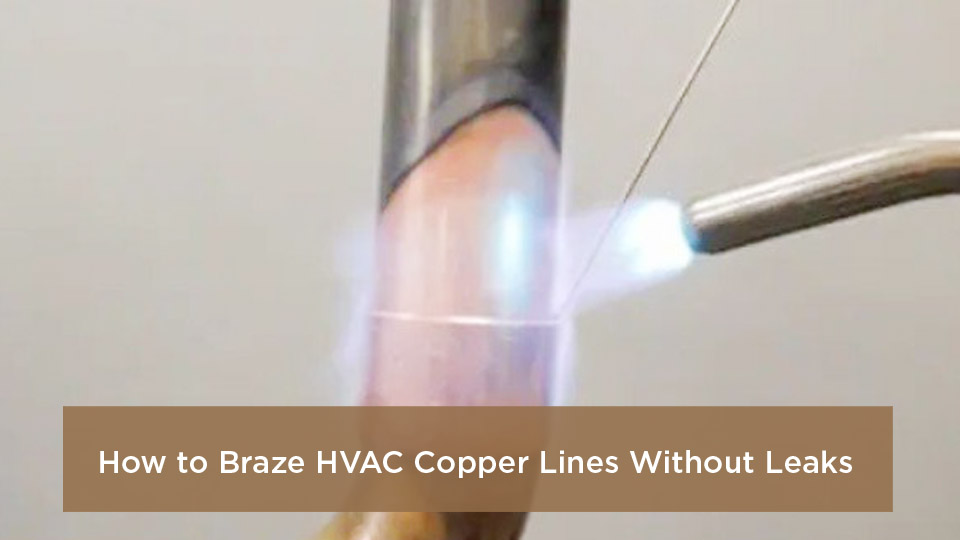
HVAC refrigerant lines experience pressure changes, temperature cycling, and vibration. A correctly designed and tested brazed joint is strong and durable, but its appearance alone cannot prove that it is leak-free.
A smooth fillet is a useful visual check, not a substitute for a regulated pressure test and manufacturer-specified evacuation test.
Brazing vs. Soldering: Which Method Should You Use?
Soldering uses filler with a liquidus below 840°F, while brazing uses higher-temperature filler. Brazing is common on refrigerant tubing because it provides better strength and fatigue resistance than soft soldering. However, the correct joining method is always the one approved by the equipment manufacturer, listing, local code, and refrigerant-system design.
| Aspect | Soldering | Brazing | Approved Mechanical Joint |
|---|---|---|---|
| Filler temperature | Below 840°F | Above 840°F and below the base-metal melting point | No filler metal |
| Typical use | Low-temperature applications where specifically permitted | Many copper refrigerant-line connections | Only where the exact connector and method are approved for the equipment |
| Advantages | Lower heat input | Strong, compact, vibration-resistant joint | No open flame when correctly installed |
| Main limitation | Often not approved for modern refrigerant circuits | Requires hot-work controls, nitrogen flow, and heat protection | Requires listed parts, specified tools, and exact installation steps |
| Decision rule | Follow the equipment installation or service manual. Do not substitute a joining method because it is faster or more familiar. | ||
Checks to Complete Before You Light the Torch
- Identify the refrigerant. Confirm whether the equipment uses a legacy A1 refrigerant or an A2L refrigerant such as R-32 or R-454B.
- Read the exact manual. Record the approved connection method, filler requirements, pressure-test value, maximum component pressure, evacuation target, and decay-test limits.
- Recover the charge. On an existing system, recover refrigerant from both the high and low sides with approved recovery equipment.
- Verify zero pressure. Never assume the entire system has equalized merely because one gauge reads zero.
- Disconnect power. Lock out or otherwise isolate every electrical source that could energize the equipment.
- Inspect the work area. Remove combustibles, protect hidden spaces, arrange ventilation, and keep a suitable fire extinguisher within reach.
- Confirm tube condition. Use clean, dry, refrigeration-grade copper that has remained capped or sealed until installation.
Warning: Never braze a charged, pressurized, or unidentified refrigerant circuit. Refrigerant or oil exposed to flame can create fire, pressure, and decomposition hazards. Recover both sides, verify zero pressure, ventilate the area, and follow the equipment’s refrigerant-specific hot-work procedure.
Essential Tools and Materials You’ll Need
A torch and rod are only part of a safe HVAC brazing setup. You also need controlled nitrogen flow, component protection, pressure-testing equipment, and proper evacuation tools.
| Tool or Material | Why It Matters | Selection Tip |
|---|---|---|
| Air-fuel or oxy-fuel torch | Provides enough heat to bring the full joint to brazing temperature | An air-fuel MAP-Pro/propylene torch may handle small accessible tubing; larger fittings often require a properly sized oxy-fuel setup |
| Correct brazing alloy | Must wet the base metals and withstand the intended service | Do not assume one rod is suitable for copper, brass, steel, and nickel-bearing parts |
| Dry-nitrogen cylinder | Displaces oxygen and limits internal copper-oxide scale | Secure the cylinder upright and use the correct cylinder connection |
| Nitrogen regulator and flow control | Provides measurable flow instead of uncontrolled cylinder pressure | Use a brazing flowmeter or flow indicator plus suitable relief protection |
| Tube cutter and reamer | Produce a square end and remove flow-restricting burrs | Ream without allowing chips to enter the tubing |
| Fitting brush and abrasive cloth | Remove oxides and contamination from the mating surfaces | Clean only enough to reach bright metal without creating a loose fit |
| Heat shields and heat-block material | Protect valves, wiring, insulation, walls, and nearby components | Use wet rags or heat-block compound where the equipment maker permits them |
| Pressure-test equipment | Verifies joint integrity before evacuation | Use a rated regulator, relief device, hoses, gauges, and approved bubble solution |
| Vacuum pump and micron gauge | Remove air and moisture and verify evacuation performance | Place the micron gauge on the system, not directly at the pump |
| PPE | Protects against flame, hot metal, radiant energy, and debris | Wear safety glasses, appropriate shaded eye protection, leather gloves, long sleeves, and flame-resistant clothing |
A low-cost torch kit is not a complete HVAC setup. Do not omit nitrogen control, recovery equipment, pressure regulation, relief protection, or evacuation tools merely to reduce the initial cost.
Products Worth Considering

Complete Kit: Ideal for HVAC & Light Duty Brazing - Designed specifically for light-duty brazing and welding jobs, this kit is your go-to tool for HVAC repairs, metal crafts, and other precision tasks. Its portable design is perfect for on-the-go professionals
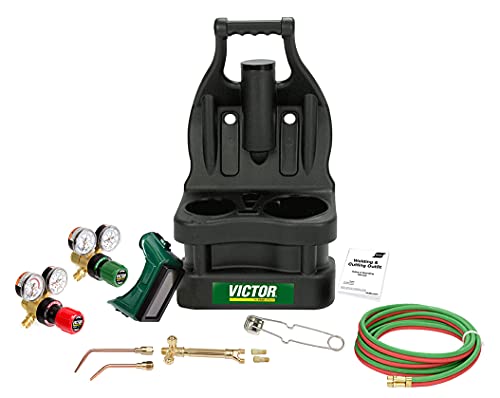
The Portable Tote from Victor features a molded, plastic carrying case with an ergonomic handle and balanced design for easy carrying.

3.6ft Hose for Extra Reach: This propane torch kit have a 3.6ft long gas hose that connects the torch to your propane/Map source, it's handy to get into small places. Warm tips: Gas bottles don't like being upside down
Choosing the Correct Brazing Alloy and Flux
Filler choice depends on both metals, not simply the tube size. The Copper Tube Handbook filler-metal table lists BCuP-5 as approximately 15% silver, with a solidus near 1,190°F and a liquidus near 1,475°F.
| Base-Metal Combination | Typical Approach | Important Caution |
|---|---|---|
| Copper to copper | BCuP-series filler such as BCuP-5 is commonly used without flux | Use the filler specified by the equipment or procedure |
| Copper to brass or bronze | Use an appropriate BCuP or BAg alloy with the flux specified for that combination | Apply flux sparingly and keep excess out of the tubing |
| Copper to steel or nickel-bearing parts | Use a manufacturer-approved silver BAg-series filler and matching flux | Do not use phosphorus-bearing BCuP filler unless an approved procedure expressly permits it |
| Compressor or valve stub | Follow the component maker’s filler, heat, and cooling instructions | The stub may be copper-plated steel rather than solid copper |
Note: Brazing flux and soldering flux are not interchangeable. Remove brazing-flux residue after the joint cools because hardened residue can corrode the assembly and may temporarily mask a small leak during testing.
Products Worth Considering

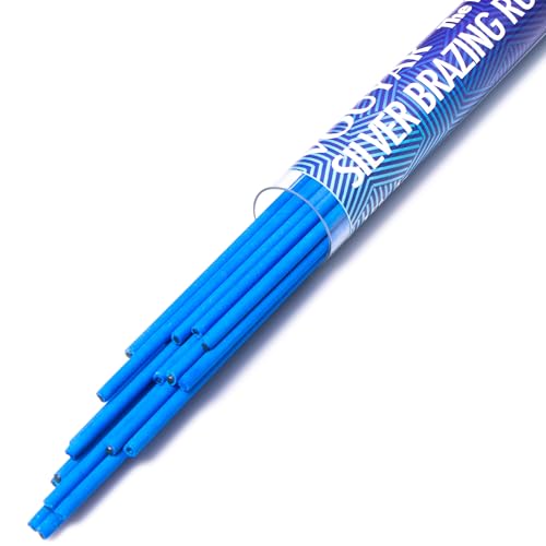
All-in-one Flux Cored Aluminum Brazing Alloy

Complete Package for Versatility: You will receive three silver brazing rods that comply with AWS A5.8 BAg-5 and QQ-B-654A BAg-5 and coated
Preparing Your Copper Lines Like a Pro
- Keep the tubing clean and dry. Leave factory caps or plugs in place until you are ready to assemble the joint.
- Cut the tube square. Avoid crushing, flattening, or spiraling the end with an overtightened cutter.
- Ream the inside diameter. Remove the full burr without dropping copper chips into the line.
- Clean both mating surfaces. Abrade the outside of the tube and the inside of the fitting cup to bright metal.
- Do not over-clean. Excess material removal can create a loose fit that weakens capillary action.
- Inspect for dents and ovality. Replace damaged tubing rather than forcing it into the fitting.
- Fully seat the joint. Mark the insertion depth so movement is easy to spot during heating.
- Support the tubing. The joint must not shift while the filler is molten or cooling.
Pro Tip: After cleaning, avoid touching the mating surfaces with bare hands or oily gloves. Skin oil, compressor oil, and cutting debris can prevent the alloy from wetting evenly.
Safety Gear and Best Practices Before You Start
Wear flame-resistant clothing, leather gloves, safety glasses with side protection, and shaded eye protection appropriate for torch brazing. OSHA’s filter-lens table lists shade 3 as the minimum for torch brazing, but the correct practice is to use the darkest suitable shade that still allows safe control of the work.
- Ventilate attics, mechanical rooms, and other restricted spaces.
- Keep cylinders upright, secured, and away from excessive heat.
- Inspect hoses, regulators, check valves, and torch connections before use.
- Protect walls, insulation, wiring, drains, framing, and concealed spaces from flame and heat.
- Use a heat shield and approved cooling method around service valves, TXVs, solenoids, filter driers, and sensors.
- Maintain a fire watch during the job and for the period required by the worksite’s hot-work rules.
- Never use oxygen, compressed air, or flammable gas to pressure-test a refrigeration circuit.
U.S. certification: EPA regulations generally require the appropriate Section 608 certification for technicians performing maintenance, service, repair, or disposal work that could release refrigerant. Qualifying apprentices must be closely and continually supervised by a certified technician.
Warning: A2L refrigerant instructions are mandatory, not optional. Confirm the refrigerant, use approved tools and joining methods, recover the charge, ventilate the work area, control ignition sources, and follow the exact installation or service manual before performing hot work.
How to Set Up a Nitrogen Purge for Brazing
Flowing dry nitrogen limits internal oxidation while the copper is hot. The gas must move through the line; pressurizing a sealed tube with static nitrogen is not the same as purging it.
- Secure the nitrogen cylinder upright.
- Install a rated nitrogen regulator, suitable hose, flow-control device, and required relief protection.
- Connect nitrogen at one end of the tubing.
- Leave the far end open or provide another controlled outlet so gas can escape.
- Purge at the flow specified by the equipment or flow-device maker until air has been displaced.
- Reduce to a low brazing flow that does not create enough pressure to disturb molten filler.
- Keep nitrogen flowing throughout heating and initial cooling.
For example, the Uniweld NitroVue instructions describe an initial purge above 20 SCFH followed by approximately 3–5 SCFH while brazing. Other tools and manufacturers may specify different values, so use the instructions for your regulator, flow indicator, tubing arrangement, and equipment.
Pro Tip: Confirm actual flow at the outlet before lighting the torch. A gauge showing pressure does not prove that nitrogen is moving through the entire line.
Step-by-Step: How to Braze HVAC Lines Without Leaks
-
Verify the system is safe for hot work.
Confirm the refrigerant, recover both sides of an existing system, verify zero pressure, disconnect power, and complete any mandatory A2L procedure.
-
Prepare and assemble the joint.
Cut square, ream, clean both mating surfaces, apply approved flux only where required, fully seat the tube, mark the insertion depth, and support the assembly.
-
Protect heat-sensitive parts.
Position heat shields and use wet rags or heat-block compound around valves, filter driers, TXVs, wiring, insulation, and finished surfaces as permitted by the equipment maker.
-
Start the nitrogen flow.
Purge the line, reduce to the specified low brazing flow, and verify that gas exits the open end.
-
Set the torch correctly.
Use the flame recommended for the torch and fuel. With oxy-fuel equipment, establish the proper neutral flame unless the approved procedure states otherwise.
-
Begin heating near the fitting.
Start on the tube immediately beside the fitting. Sweep the flame around the tube and fitting, spending enough time on the heavier fitting to bring both pieces to a uniform temperature.
-
Test the temperature with the filler.
Touch the alloy to the joint on the side opposite the flame. The heated base metal—not direct flame on the rod—should melt the filler.
-
Feed the alloy around the joint.
Keep the flame slightly ahead of the filler and let capillary action draw the molten alloy into the fitting cup. Stop when a complete fillet is visible; excess alloy does not improve the joint.
-
Finish horizontal and vertical joints carefully.
On a horizontal joint, begin near the bottom and work upward on both sides with a slight overlap. On a downward-facing socket, avoid overheating the tube and causing the alloy to run down the outside.
-
Remove heat and allow the alloy to solidify.
Do not move the joint while the filler is molten. Continue nitrogen flow during initial cooling. Follow the component manual if it directs controlled wet-cloth cooling around a service valve; otherwise allow the fitting to cool naturally before washing.
-
Clean and inspect.
Remove flux residue using the approved method. Inspect the entire circumference for alloy flow, cracks, pinholes, overheating, movement, or incomplete seating.
-
Pressure-test and evacuate.
Use the exact dry-nitrogen or dry-helium pressure, hold time, and acceptance criteria stated by the equipment maker. Repair and retest any leak before beginning evacuation.
Torch Tips and Flame Control
Match the heat source and tip to the tubing size, fitting mass, joint access, and nearby components. A flame that is too small keeps the joint hot for too long, while an oversized flame can overheat valves, oxidize the copper, or burn through thin tubing.
- Keep the hottest part of the flame moving rather than parking it on one point.
- Heat the base metals, not the end of the filler rod.
- Work around the circumference so the back of the joint reaches the same temperature as the front.
- Spend more time on the heavier fitting while continuing to sweep across the tube.
- Feed filler on the side opposite the flame so capillary action can pull it toward the heat.
- Reduce heat as soon as the alloy begins flowing freely.
Note: Copper color is an unreliable temperature gauge in bright light, dark attics, or around flux. Use the behavior of the approved filler and flux, along with practiced heat timing, instead of trying to reach a particular surface color.
Common Mistakes I Learned the Hard Way and How to Fix Them
- Dirty mating surfaces: The filler balls up or refuses to enter the joint. Clean both surfaces to bright metal and keep them oil-free.
- Heating only the fitting: One part becomes much hotter than the other, and alloy runs outside. Sweep the flame around both pieces.
- Melting the rod with the flame: Alloy drops onto a cold joint without bonding. Let the base metal melt the filler.
- No nitrogen flow: Black copper-oxide scale forms inside the line and may later reach screens, valves, or oil-return passages.
- Sealing the purge outlet: Pressure builds and can push molten alloy out of the joint. Maintain an open flow path.
- Using the wrong filler on steel: A phosphorus-bearing rod can create a brittle joint. Use the alloy and flux specified for the actual metal combination.
- Too much flux: Residue enters the line, corrodes surfaces, or temporarily masks a leak. Apply only the approved amount.
- Overheating a service valve: Internal seals or nearby components are damaged. Use heat protection and follow the valve or unit manual.
- Adding unsupported loops or traps: Improvised piping changes can affect oil return. Support and route tubing exactly as the equipment maker specifies.
- Skipping the standing-pressure test: A vacuum is pulled on an unverified system. Pressure-test and repair first.
Troubleshooting Brazed HVAC Copper Joints
| Symptom | Likely Cause | Corrective Action |
|---|---|---|
| Filler balls up | Dirty or oxidized surfaces, insufficient base-metal heat, or incompatible filler | Stop, cool, disassemble if possible, reclean, verify the alloy, and heat the full joint evenly |
| Filler runs down the outside | Uneven heating, oversized clearance, or direct flame on the rod | Equalize heat, confirm fit, and feed the rod opposite the flame |
| Black flakes inside the tube | No nitrogen flow, insufficient purge, or a blocked outlet | Correct the purge setup; replace or clean contaminated sections as required by the equipment procedure |
| Tube becomes deeply scaled or distorted | Excessive heat or an oversized flame | Stop and inspect for wall damage; replace compromised tubing rather than covering it with more filler |
| Joint cracks after cooling | Movement during solidification, poor fit, incompatible filler, or severe overheating | Cut out the joint and remake it with correct support, fit, alloy, and heat control |
| Pressure test drops | Leak, temperature change, leaking test connection, or instrument problem | Allow temperature to stabilize, verify the test rig, apply bubble solution, locate the leak, repair, and repeat the full test |
| Vacuum rises quickly | Gross leak, open valve, leaking hose, or loose core tool | Stop evacuation and perform a pressure test rather than continuing to run the pump |
| Vacuum rises slowly | Moisture, outgassing, a small leak, or contaminated oil | Check the manual’s decay limits, verify the test setup, change pump oil if needed, and repeat evacuation or leak testing |
Testing Your Joints: Pressure Test First, Then Evacuate
1. Perform a visual inspection
Check that the tube remains fully seated and that alloy has flowed around the entire joint. Look for cracks, pinholes, overheated copper, burned component paint, or flux residue. A visually good joint still requires testing.
2. Connect regulated dry nitrogen
Use a rated regulator, relief device, hoses, and gauges. Never connect an unregulated cylinder directly to the refrigeration system.
3. Use the exact test pressure in the equipment manual
Do not use a universal 150 psi, 300 psi, or 450 psi value. The approved pressure and hold time vary by product and may be limited by the coil, compressor, service valves, accessories, or refrigerant classification.
4. Stabilize and inspect for leaks
Allow pressure and tubing temperature to stabilize. Apply an approved bubble solution to every new joint, service connection, valve cap, and test-hose connection. Repair any leak and repeat the complete standing test.
5. Use electronic detection correctly
A refrigerant detector cannot detect plain nitrogen. Use electronic detection only with a compatible approved tracer or after charging, and only when the equipment procedure and regulations permit it. Ultrasonic equipment may help locate escaping nitrogen but does not replace the specified standing test.
6. Release the test gas safely
Reduce pressure in a controlled manner and follow site rules for discharge. Do not open service valves containing the factory charge until pressure testing and evacuation are complete.
7. Connect the vacuum equipment
Use clean vacuum-rated hoses, a suitable pump, and a micron gauge connected to the system away from the pump. Remove Schrader cores with rated core tools where the manufacturer permits it.
8. Pull the required deep vacuum
Many equipment manuals require 500 microns or less, but the exact target and duration belong to the product procedure. Evacuate from both sides when the system design or manufacturer requires it.
9. Isolate the pump and perform the decay test
Close the system from the pump and watch the system-side micron gauge for the specified hold period. A rapid rise usually points to a leak or test-rig problem. A slower rise can indicate moisture, outgassing, or a small leak. Apply the manufacturer’s acceptance limits rather than assuming any rise is acceptable.
10. Use triple evacuation only when appropriate
A dry-nitrogen vacuum break and repeated evacuation can help remove moisture when the product procedure allows it. Triple evacuation cannot repair a leak and should not be used to avoid a failed standing-pressure test.
Warning: Never pressure-test with oxygen, high-pressure air, acetylene, propane, or another flammable gas. Use only the dry test gas, regulated pressure, relief protection, and acceptance criteria approved for the equipment.
Sources
- Copper Development Association — Copper Tube Handbook — brazing preparation, filler metals, flux, cooling, testing, and inert-gas purging.
- Copper Development Association — Soldering and Brazing Explained — brazing definition, temperature distinction, and filler categories.
- Uniweld NitroVue Flow Indicator — example purge and low-flow brazing settings.
- Daikin R-32 Condensing Unit Installation Manual — A2L joining, pressure testing, leak detection, and evacuation procedures for the referenced equipment.
- U.S. EPA Section 608 Technician Certification Requirements — current U.S. refrigerant-service certification rules.
- OSHA 29 CFR 1910.133 — eye and face protection and minimum filter-lens guidance.
Frequently Asked Questions
Can beginners braze HVAC copper lines safely?
A beginner can practice torch control and capillary flow on clean scrap copper in a safe training area. Opening or repairing a refrigerant circuit adds pressure, fire, refrigerant, electrical, and regulatory hazards. In the United States, work that could release refrigerant generally requires the appropriate EPA certification or qualifying supervised-apprentice status.
What is the best brazing rod for copper refrigerant lines?
A 15% silver copper-phosphorus alloy classified as BCuP-5 is a common choice for copper-to-copper HVAC joints and normally requires no flux on clean copper. It is not automatically correct for brass, steel, nickel-bearing parts, or every manufacturer procedure.
Do I need flux every time I braze HVAC lines?
No. A BCuP filler normally self-fluxes on copper-to-copper joints. Copper-to-brass, cast components, BAg filler, steel, and nickel-bearing materials may require a specific brazing flux. Follow the filler and equipment instructions, apply flux sparingly, and remove the residue after cooling.
How much nitrogen should flow while brazing?
Use the value specified by the equipment or flow-control manufacturer. The goal is a continuous low flow through an open outlet, not high pressure. One common HVAC flow indicator calls for an initial purge above 20 SCFH and approximately 3–5 SCFH during brazing, but other procedures may differ.
Can I seal both ends while flowing nitrogen?
No. Nitrogen needs an open or controlled outlet so it can displace air and continue moving through the tubing. A sealed line creates static pressure that can disturb molten filler or exceed a component’s rating.
Can I use a MAP-Pro torch on HVAC copper?
An air-fuel MAP-Pro or propylene torch may provide enough heat for smaller, accessible copper joints. Large fittings, heavy valves, wind, or restricted access may require a correctly sized oxy-fuel setup. Use the torch, fuel, and tip approved for the tubing size and work area.
What pressure should I use to leak-test an HVAC line set?
Use the exact dry-nitrogen or dry-helium pressure stated in the equipment installation or service manual, while respecting the lowest-rated component. There is no safe universal pressure for every refrigerant system. Use a regulator, relief protection, rated test equipment, and the required hold time.
Does pulling 500 microns prove the brazed joint is leak-free?
No. Reaching a low vacuum is part of dehydration and evacuation. A manufacturer-specified vacuum-decay test can reveal a leak or remaining moisture, but it does not replace a regulated standing-pressure test and bubble inspection.
Why is the inside of my copper tubing black after brazing?
Black scale usually forms when oxygen remains inside hot copper because nitrogen was absent, blocked, or not flowing. The flakes can travel through the system and affect screens, expansion devices, and oil-return passages. Correct the purge setup before remaking the joint.
Why braze instead of soldering AC lines?
Brazed joints generally provide greater strength and fatigue resistance for refrigerant service. Even so, the final decision must follow the equipment manual and code because some systems permit approved mechanical connections and some applications have special joining requirements.
Related Articles
U.S. compliance note: EPA regulations prohibit intentional venting of covered refrigerants and generally require the appropriate Section 608 certification for technicians whose maintenance, service, repair, or disposal work could release refrigerant.