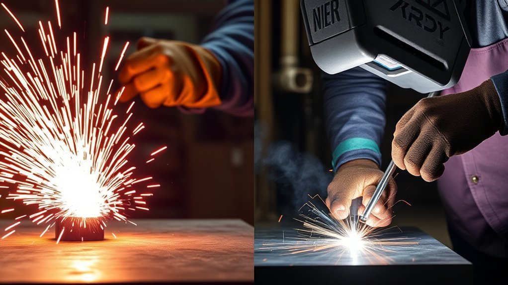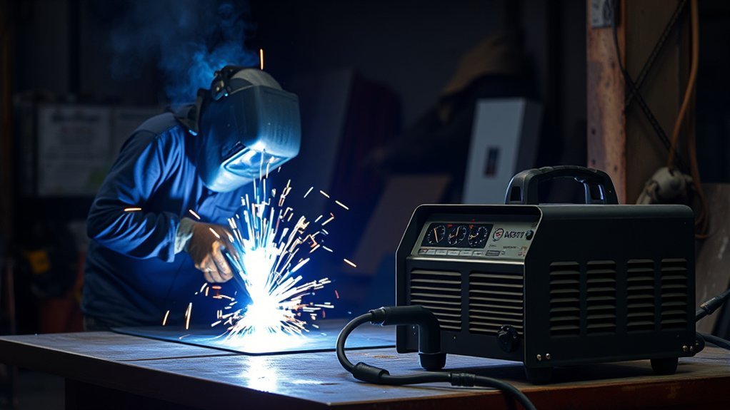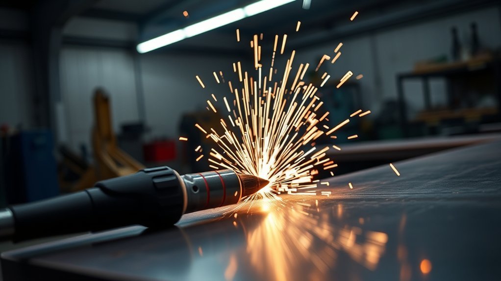
A standard plasma cutter cannot be used as a welder. Its cutting torch is designed to melt metal and blow it out of the cut, while a welder is designed to fuse two pieces together. You can still weld metal after plasma cutting, but the edge must be inspected and prepared well enough for the material, joint, and welding procedure.
Quick Answer
No. A standard plasma cutter is designed to remove metal, not join it. You can weld parts after plasma cutting, and some multi-process machines include separate plasma-cutting and welding modes. Inspect the cut edge first, remove dross or contamination when needed, prepare the joint, and then weld with the correct process and settings.
Key Takeaways
- A plasma-cutting torch removes metal; it does not perform MIG, TIG, stick, or plasma arc welding.
- Plasma arc welding is a separate process that uses different equipment and operating controls.
- Some plasma-cut edges need grinding, but a clean, low-dross edge may require little or no secondary work.
- Air-plasma cutting can leave oxidation and nitriding that may contribute to weld porosity.
- Critical welds must follow the approved joint design, welding procedure, and inspection requirements.
At a Glance
| Time Required | About 10–30 minutes for a typical small joint |
| Difficulty | Easy to moderate; joint design may require advanced welding knowledge |
| Tools Needed | Pliers or a chipping tool, file or angle grinder, suitable abrasive, clean brush, approved cleaner, clamps, and PPE |
| Cost | Usually $0–$20 in abrasives and cleaning supplies if you already own the tools and PPE |
Plasma Cutter vs. Welder: The Key Difference
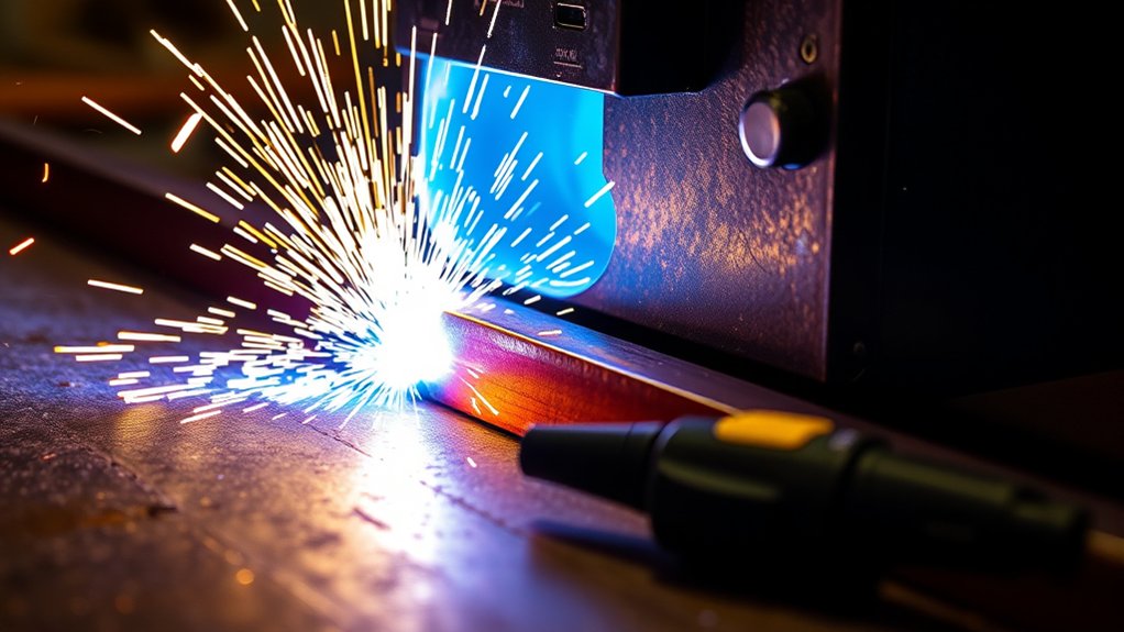
A plasma cutter forms an electrical arc and forces ionized gas through a narrow torch opening. The high-temperature, high-velocity jet melts the workpiece, and the gas stream pushes the molten metal out of the kerf. This process separates electrically conductive metal instead of joining it. You can read more about the process in Lincoln Electric’s explanation of how a plasma cutter works.
A welder does the opposite. It creates a controlled molten pool that fuses the base metals, often with filler metal and shielding gas or flux. MIG, TIG, stick, and flux-cored machines each use a welding circuit, torch or electrode holder, and controls designed for joining.
A cutting arc removes molten metal from a kerf. A welding arc keeps molten metal in the joint so it can fuse and solidify.
Plasma arc welding does exist, but it is not the same as using an ordinary plasma cutter as a welder. Plasma arc welding is a specialized process related to TIG welding. It uses a constricted arc, controlled plasma gas, shielding gas, and welding-specific equipment to melt and join the workpiece. ESAB describes plasma arc welding as a separate precision welding process.
Some all-in-one machines contain a plasma cutter plus TIG or stick functions. These machines can perform both jobs because they have separate operating modes, connections, torches, and controls. Selecting the plasma-cutting mode does not turn the cutting torch into a welding torch.
Can You Weld Metal After Plasma Cutting?
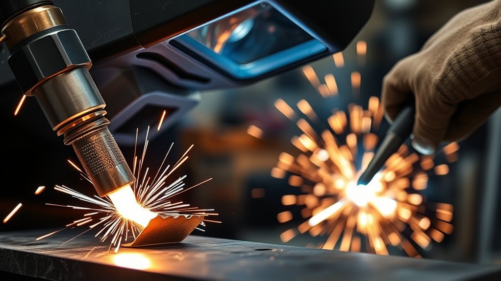
Yes. Plasma-cut steel, stainless steel, and aluminum can be welded when the cut geometry, surface condition, and joint preparation are suitable for the welding process.
The edge may contain attached dross, oxide, nitrides, rough striations, bevel, moisture, paint, oil, or other contamination. These conditions can make the arc less stable and increase the risk of porosity, slag inclusions, poor wetting, incomplete fusion, or irregular bead shape.
However, a plasma cut is not automatically unweldable. Correct torch height, cutting speed, amperage, gas selection, and consumable condition can produce a smooth edge with little or no attached dross. Modern high-definition systems may create a weld-ready plasma edge that can move directly to fit-up and welding when the applicable procedure permits it.
Warning: Do not guess at edge preparation for structural frames, lifting equipment, pressure vessels, roll cages, vehicle suspension parts, pipelines, or other critical welds. Follow the approved drawing, welding procedure specification, material requirements, and inspection rules. Use a qualified welder when failure could cause injury or major property damage.
How Plasma Cutting Affects the Metal Edge
A plasma-cut edge can have several features that matter during welding:
- Dross: Re-solidified metal attached to the bottom or side of the cut. Thick dross can block fit-up or enter the weld pool.
- Oxide: A dark surface layer created as the hot metal reacts with oxygen. Heavy oxide should be removed from the weld zone.
- Nitriding: Air-plasma cutting can introduce nitrogen into the cut surface. On some materials and welds, this can contribute to porosity.
- Heat-affected zone: The narrow area beside the kerf experiences rapid heating and cooling. Its effect depends on the alloy, thickness, cutting process, and application.
- Bevel and striations: A cut may not be perfectly square. Excessive bevel, drag lines, or gouges can create poor root gaps and inconsistent penetration.
- Sharp burrs: Even a low-dross cut may have sharp areas that interfere with handling or fit-up.
Air is common in portable plasma systems because it is convenient and versatile. However, Hypertherm notes that air plasma can cause nitriding and oxidation that may affect weldability. Oxygen plasma is often used for cleaner, more weld-friendly cuts on mild steel, while stainless steel and aluminum require gas and consumable choices suited to those materials.
Material-Specific Weld Preparation
| Material | What to Check | Typical Preparation |
| Mild steel | Dross, oxide, nitrided air-plasma surface, bevel, mill scale, paint, or rust | Remove attached dross and contamination. Grind the weld zone when required by edge condition or procedure. |
| Stainless steel | Heavy oxide, heat tint, embedded carbon-steel particles, moisture, oil, and poor joint geometry | Use clean abrasives and brushes reserved for stainless steel. Remove contamination without embedding ordinary carbon steel. |
| Aluminum | Aluminum oxide, soot, moisture, rough kerf surfaces, and contamination from unsuitable abrasives | Smooth the edge with a nonferrous-rated abrasive, clean it with an approved nonchlorinated product, and use a dedicated stainless brush when brushing is required. |
How to Prepare Plasma-Cut Metal for Welding
- Let the part cool and inspect it. Look for loose dross, dark oxide, heavy bevel, gouges, cracks, coatings, oil, moisture, and an uneven root gap.
- Confirm the joint requirements. Check whether the joint needs a square edge, bevel, root face, backing, or a specified gap. Critical work must follow the drawing and welding procedure.
- Secure the workpiece. Clamp the part before using pliers, a file, chipping tool, or grinder. Do not hold a small piece in one hand while grinding it with the other.
- Remove loose dross. Break away easily detached dross with pliers, a scraper, or a suitable chipping tool. Avoid hammering thin sheet hard enough to bend it.
- Grind the remaining contamination. Use a grinding wheel, flap disc, file, or belt abrasive to remove stubborn dross and contaminated surface material from the weld zone.
- Shape and deburr the joint. Correct excessive bevel, smooth sharp edges, and prepare the required joint geometry without thinning the part more than necessary.
- Remove coatings and residue. Clean away paint, rust, oil, marker residue, and grinding dust. Use only a nonchlorinated cleaner approved for the material, follow its safety data sheet, and let the surface dry fully.
- Check fit-up. Clamp the pieces in position and verify the gap, alignment, root opening, and accessibility before tacking.
- Test when the material or cut is unfamiliar. Make a test weld on matching scrap, then inspect it for porosity, cracking, fusion, bead shape, and penetration before welding the final part.
Pro Tip: Grind only as much as needed to remove contamination and create the required joint shape. Excessive pressure or long dwell time can overheat thin sheet, round over an edge, enlarge the root gap, or remove more base metal than intended.
Warning: Do not use chlorinated brake cleaner or another chlorinated degreaser on metal that will be welded or heated. OSHA warns that residues from chlorinated hydrocarbons can form hazardous decomposition products when exposed to welding heat or radiation. Use an approved nonchlorinated cleaner and allow it to evaporate completely.
Why Clean Surfaces Matter
Welding processes tolerate contamination differently, but all benefit from correct joint preparation. Dross, heavy oxide, paint, oil, moisture, and grinding debris can enter the molten pool or interfere with shielding and fusion.
TIG welding is especially sensitive because the process uses no flux to help manage surface contamination. MIG and flux-cored welding may appear more forgiving, but contamination can still cause porosity, spatter, inclusions, or an irregular bead. Stick electrodes can tolerate some field conditions, but they do not make attached plasma dross an acceptable part of a weld joint.
A clean edge also improves fit-up. When the root gap and joint faces are consistent, it is easier to maintain travel speed, arc length, penetration, and bead size.
Removing Dross Effectively
Dross is re-solidified metal that remains attached after the molten material is blown from the kerf. Some dross can be snapped off easily, while heavy or strongly attached deposits need an abrasive.
- Start with pliers, a scraper, or a chipping tool when the dross is loose.
- Use a file for small parts or areas where a grinder would remove too much metal.
- Use a hard grinding wheel for thick deposits and major edge correction.
- Switch to a flap disc when you need more control or a smoother finish.
- Clean both joint faces and the nearby surfaces that will be melted by the arc.
- Recheck the joint gap after grinding because edge cleanup can change fit-up.
A wire brush can remove loose dust, light oxide, or residue, but it normally will not remove thick attached dross. Do not polish over a deposit and assume the underlying edge is clean.
Tools for Metal Cleaning
An angle grinder is the fastest general-purpose option for many plasma-cut steel parts, but it is not the only choice. Select the tool according to the material, thickness, edge condition, and amount of control required.
- Hard grinding wheel: Best for heavy dross, rough cuts, and major shaping. It removes metal quickly but can gouge thin material.
- Flap disc: Useful for controlled cleaning, blending, and finishing. Coarse grits remove contamination faster; finer grits smooth the final surface.
- Hand file: Good for small parts, thin sheet, tight spaces, and precise burr removal.
- Belt grinder or linisher: Efficient for batches of straight edges when the work can be supported safely.
- Wire brush: Useful for loose surface material, but not a substitute for grinding attached dross.
- Deburring tool: Useful for light burrs on thin sheet after the main contamination is removed.
Use abrasives that are rated for the tool speed and suitable for the base metal. Keep stainless-steel and aluminum cleaning tools separate from ordinary carbon-steel work when cross-contamination could affect corrosion resistance or weld quality.
Products Worth Considering
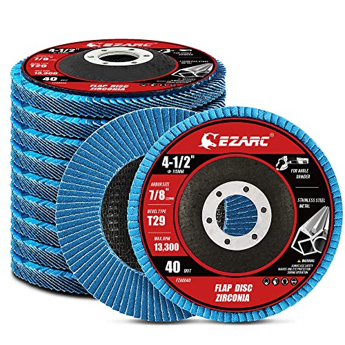
【Great Performance】EZARC flap sanding discs are made of hard zirconia material which lasts longer than standard aluminum oxide abrasive material, built for a more robust and economical grinding wheel

STRONGEST FIBER BACKING THAN OTHER PRODUCTS:4 1/2 grinding wheels made for TOP-LEVEL Hard zirconia.Good material for griding wheel. This Flap Disc is constructed of industrial grade high density premium zirconia material, increased durability than standard flap discs, built for a more robust and economical grinding wheel

HIGH-DENSITY JUMBO DESIGN: Type 29 flap discs with a high-density jumbo layout support surface blending, beveling, grinding, deburring, and edge chamfering. Curved profile aids finishing, stock removal, and rust cleanup for pros and DIY enthusiasts
Comparing Welds: Clean vs. Contaminated Edges
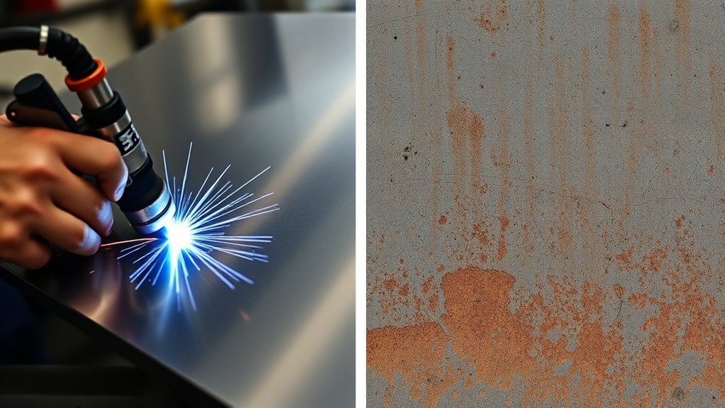
| Factor | Properly Prepared Edge | Contaminated or Poorly Fitted Edge |
| Arc behavior | More stable and easier to position | May pop, wander, or behave irregularly |
| Weld pool | Predictable wetting and movement | May spit, resist wetting, or trap contamination |
| Bead consistency | More uniform width and profile | May become uneven, convex, undercut, or heavily spattered |
| Defect risk | Lower contamination-related risk when the procedure is correct | Higher risk of porosity, inclusions, lack of fusion, and poor fit-up |
| Final strength | Can meet the required result when joint design, filler, settings, and technique are correct | Cannot be judged from appearance alone and may require repair or rejection |
Cleaning reduces contamination-related problems, but it does not guarantee a sound weld. Correct filler metal, polarity, shielding gas, current, travel speed, joint geometry, technique, and inspection still matter.
Tools for Effective Surface Cleaning
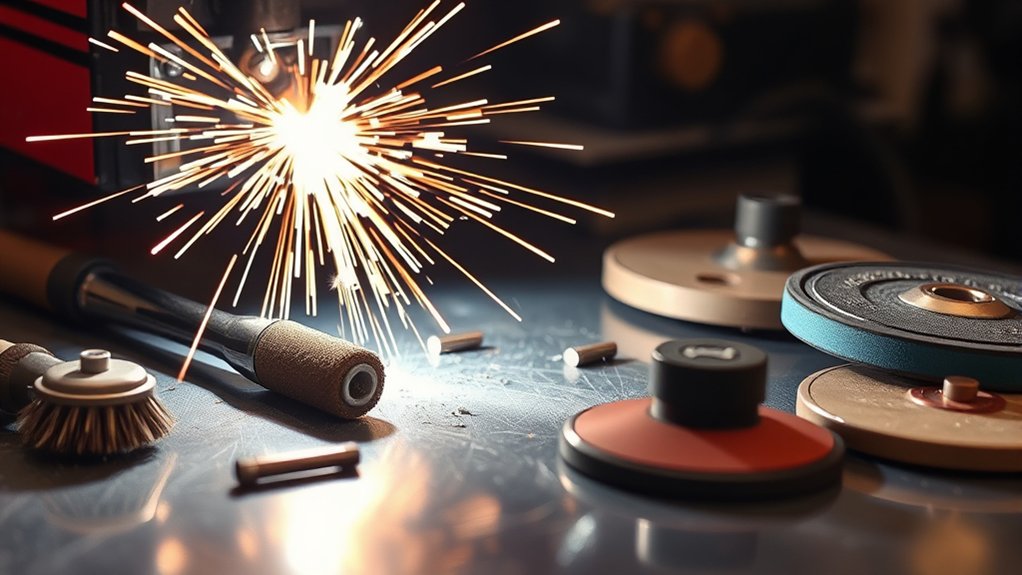
Hard grinding wheels and flap discs are the most common power-tool choices, but they serve different purposes.
Hard grinding wheels remove thick dross and reshape rough edges quickly. They are useful when the cut has a heavy deposit or excessive bevel. Their aggressive action also makes it easier to gouge the base metal, especially on thin sheet.
Flap discs combine stock removal and surface blending. Their overlapping abrasive flaps conform slightly to the workpiece, making them useful for smoothing straight or curved edges. They still create heat, so use light pressure and keep the tool moving.
For a rough plasma cut, a practical sequence is to remove loose dross mechanically, use a hard wheel only where needed, and finish the weld zone with a controlled abrasive. A good-quality cut may need nothing more than light deburring and cleaning.
Products Worth Considering

Package Include 24 pcs grinding wheels 4 1/2 inch grit 40 60 80 120,6 of each

【Professional Flap Disc】The 50pcs flap discs 4 1/2 for angle grinder include 20pcs for 40 grit, 10pcs for 60 grit, 5pcs for 80 grit, 5pcs for 120 grit, and 10pcs for 40 grit flap disc T27. Covering grits from 40 to 120 for versatile material removal and finishing.

PREMIUM QUALITY: These angled flap discs, also known as cut off wheels 4 1/2 inch, are constructed with industrial grade premium zirconia abrasive for strength, durability, and extended disc life as it holds up to high temperatures and pressure.
Grinding Wheels: Benefits and Limits
- Fast removal: Effective on thick, stubborn dross.
- Edge correction: Useful for reducing severe bevel or high spots.
- Joint shaping: Can form a bevel or root face when used carefully.
- Long service life: A suitable wheel can handle repeated heavy cleanup.
- Main limitation: Aggressive wheels can gouge, overheat, or thin the base metal.
Keep the grinder guard installed, use the correct wheel for the tool’s rated speed, inspect the wheel before use, and position your body away from the wheel’s plane.
Flap Discs: Advantages and Limits
- Controlled removal: Easier to blend a surface without deep gouges.
- Smoother finish: Leaves a more uniform joint face than a coarse hard wheel.
- Useful on curves: The flaps can follow slightly rounded shapes.
- Multiple grit options: Coarse grits remove material; finer grits refine the finish.
- Main limitation: A flap disc is slower on thick, glass-hard deposits and can still remove too much metal.
Do not use the side of a disc unless the manufacturer specifically rates it for that use. Replace damaged, glazed, contaminated, or worn-out abrasives.
Choosing the Right Cleaning Tool
- Use pliers or a scraper for loose dross that releases without damaging the edge.
- Use a file when precision matters more than speed.
- Use a hard wheel for heavy deposits or major reshaping.
- Use a flap disc for controlled cleanup and blending.
- Use a clean material-specific brush only after attached contamination has been removed.
- Use dedicated abrasives for stainless steel and aluminum when cross-contamination matters.
- Use a belt grinder for repeated straight-edge cleanup when the work can be held safely.
Recommendations for Optimal Welding Practices
- Inspect before grinding. Do not remove metal automatically when the edge is already clean, square, and acceptable under the procedure.
- Clean the full weld zone. Include both joint faces and nearby surfaces that will melt or affect shielding.
- Correct the geometry. Remove high spots and excessive bevel that prevent consistent root spacing.
- Use clean filler and consumables. Contaminated wire, electrodes, tungsten, cups, nozzles, or liners can create problems even when the base metal is clean.
- Check the work-clamp connection. Attach it to clean conductive metal close enough to provide a reliable circuit.
- Match the welding process to the material. Use the correct filler classification, shielding gas, polarity, and settings.
- Tack and recheck alignment. Heat and tack sequence can move parts after the initial fit-up.
- Inspect the finished weld. Look for visible porosity, cracks, undercut, overlap, incomplete fill, or irregular fusion.
Note: Grinding is surface preparation, not a substitute for a qualified welding procedure. A shiny edge can still have the wrong bevel, root opening, filler metal, heat input, or penetration for the application.
How to Reduce Dross Before It Forms
Better cutting technique reduces the amount of cleanup needed before welding. Follow the machine’s cut chart and owner’s manual rather than relying on one setting for every thickness.
- Use the recommended amperage for the material and thickness.
- Maintain the specified torch-to-work distance or shield position.
- Travel at the correct speed. Moving too slowly or too quickly can increase dross and bevel.
- Keep the torch square to the work unless making an intentional bevel.
- Supply clean, dry gas or compressed air at the required pressure and flow.
- Inspect the nozzle, electrode, shield, and other consumables for wear or damage.
- Use a guide when a straight, square edge is important.
- Start and end the cut where pierce marks will not remain in the weld zone when possible.
Miller’s plasma-cutting guidance explains how technique and consumable condition affect cut quality and dross formation.
When a Plasma-Cut Edge May Be Weld-Ready
A plasma-cut edge may be ready for immediate welding when all of the following are true:
- No attached dross remains in or beside the joint.
- The edge has no contamination that could interfere with fusion or shielding.
- The cut geometry provides the required bevel, root face, gap, and alignment.
- The material and cutting gas do not create an unacceptable weldability concern.
- The applicable welding procedure permits the cut condition.
- A test or established production process has shown consistent weld results.
This condition is more common with well-controlled mechanized or high-definition cutting than with a rough freehand cut. When in doubt, cleaning and testing the joint is safer than assuming it is ready.
Exploring Alternative Cutting Methods
Another cutting process may reduce one type of preparation, but no cutting method guarantees a weld-ready joint. Inspect the edge, remove contamination, and correct the geometry before welding.
| Method | Main Advantage | Possible Weld Preparation |
| Plasma cutting | Fast cutting of many conductive metals with good shape flexibility | Remove dross, oxide, nitrided surface, bevel, or roughness when present |
| Oxy-fuel | Cuts thick carbon steel without a high-current electrical power source | Often requires removal of oxide scale, slag, roughness, and heat-affected material |
| Laser cutting | Narrow kerf, accurate geometry, and high production speed | Inspect for oxide, nitriding, burrs, coatings, and assist-gas effects |
| Waterjet | Cold cutting without a thermal heat-affected zone | Dry the edge and remove moisture, abrasive residue, burrs, or taper as needed |
| Band saw | Cool mechanical cutting with a relatively square edge | Remove burrs, cutting fluid, chips, rust, and poor fit-up |
| Shear | Fast straight cuts in suitable sheet metal | Correct burrs, rollover, edge deformation, coatings, and alignment |
Plasma Cutting and Edge-Preparation Safety
- Wear eye and face protection with a filter shade appropriate for the cutting current and the machine manufacturer’s instructions.
- OSHA’s general-industry table lists shade 8 for plasma arc cutting below 300 amps, shade 9 from 300–400 amps, and shade 10 from 400–800 amps.
- Wear impact-rated safety glasses under a cutting shield or helmet, plus flame-resistant clothing, suitable gloves, hearing protection, and protective footwear.
- Provide suitable ventilation and control fumes from the base metal, coatings, plating, and cleaning products.
- Remove paint and coatings far enough from the hot-work area to prevent them from burning into the fumes or weld.
- Keep combustibles away from sparks and hot slag. In covered workplaces, OSHA generally requires relocating combustibles at least 35 feet where practicable or protecting them by other approved means.
- Keep appropriate fire-extinguishing equipment available and use a fire watch when required.
- Never cut a sealed container or a container that held fuel, solvent, gas, oil, or another flammable material unless it has been professionally cleaned, tested, vented, and authorized for hot work.
- Treat freshly cut metal as hot even when it is no longer glowing.
- Disconnect power before changing plasma consumables or servicing the cutter. Unplug the grinder before changing an abrasive.
Frequently Asked Questions
Can the same plasma-cutting torch be used to weld?
No. A standard cutting torch, nozzle, gas flow, and power-control setup are designed to remove molten metal. Welding requires welding-specific equipment and controls. A combination machine may weld through a separate TIG or stick connection, but not through its ordinary plasma-cutting torch.
Can a plasma cutter be used for non-metal materials?
A standard handheld transferred-arc plasma cutter requires an electrically conductive workpiece, such as steel, stainless steel, aluminum, brass, or copper. It is not intended for ordinary cutting of wood, plastic, glass, concrete, or other nonconductive materials.
Can you weld a plasma-cut edge without grinding it?
Sometimes. An edge with no attached dross, harmful contamination, excessive bevel, or fit-up problem may be weld-ready. Grinding is still appropriate when the edge has air-plasma contamination, heavy oxide, roughness, coatings, or a joint shape that does not meet the welding procedure.
Why does a weld become porous after plasma cutting?
Possible causes include nitriding or oxidation from the cutting process, attached dross, moisture, paint, oil, unsuitable cleaner residue, contaminated filler, poor shielding-gas coverage, or incorrect welding parameters. Clean the joint, verify gas flow and consumables, and test matching scrap before repairing a critical part.
What safety gear is required when using a plasma cutter?
Use impact-rated eye protection plus a cutting shield or helmet with the filter shade required for the cutting current, equipment manual, and applicable rules. Also wear flame-resistant clothing, suitable gloves, hearing protection, and protective footwear. Provide ventilation and protect nearby people from arc radiation and sparks.
How does metal thickness affect plasma cutting?
The cutter does not change the original plate gauge away from the kerf, but it removes material and creates a narrow heat-affected zone along the cut. Thicker metal normally needs more current, the correct consumables, slower travel, and enough machine capacity. Follow the manufacturer’s cut chart rather than estimating settings.
Does a plasma cutter need a special power source?
The required voltage, input amperage, breaker, receptacle, extension cord, and compressed-air supply depend on the exact machine. Some portable units accept more than one input voltage, while larger machines require a dedicated higher-voltage circuit. Read the data plate and manual before connecting the cutter. See the separate guide explaining whether a plasma cutter needs compressed air.
Can plasma cutters be used underwater?
Specialized mechanized plasma systems can operate with controlled water tables or underwater-cutting procedures. An ordinary handheld shop plasma cutter must not be submerged or used underwater. Water, electricity, molten metal, gas selection, and possible hydrogen accumulation create severe hazards that require purpose-built equipment and trained operators.
Conclusion
A standard plasma cutter cannot replace a welder because its torch is designed to remove molten metal instead of forming a joint. Plasma arc welding and multi-process machines do exist, but they use dedicated welding equipment or separate operating modes.
You can weld plasma-cut metal successfully. First inspect the edge instead of assuming that every cut must be heavily ground. Remove attached dross, oxide, nitrided or contaminated surface material, coatings, and poor geometry when they could interfere with the joint. Then verify fit-up, use the correct welding procedure, and make a test weld when the material or cut condition is unfamiliar.
Good plasma settings can reduce cleanup, and advanced systems may produce weld-ready edges. For critical work, however, edge appearance alone is not enough. Joint design, filler metal, heat input, welder qualification, and inspection remain essential.
Sources
- Lincoln Electric — How a Plasma Cutter Works — supports the explanation of the plasma-cutting arc and metal-removal process.
- ESAB — GTAW and Plasma Arc Welding — supports the distinction between plasma cutting and plasma arc welding.
- Hypertherm — Guide to Plasma Gas Selection — supports air-plasma nitriding, oxidation, gas selection, and weldability guidance.
- Hypertherm — What Weld Ready Means — supports the explanation of weld-ready plasma-cut edges.
- OSHA 29 CFR 1910.133 — Eye and Face Protection — supports current-based plasma-cutting filter-shade guidance.
- OSHA 29 CFR 1910.252 — Welding, Cutting, and Brazing — supports hot-work fire prevention, combustible control, and protective-equipment requirements.