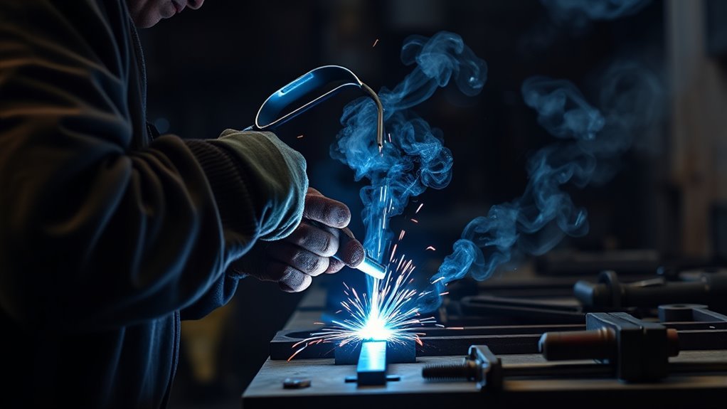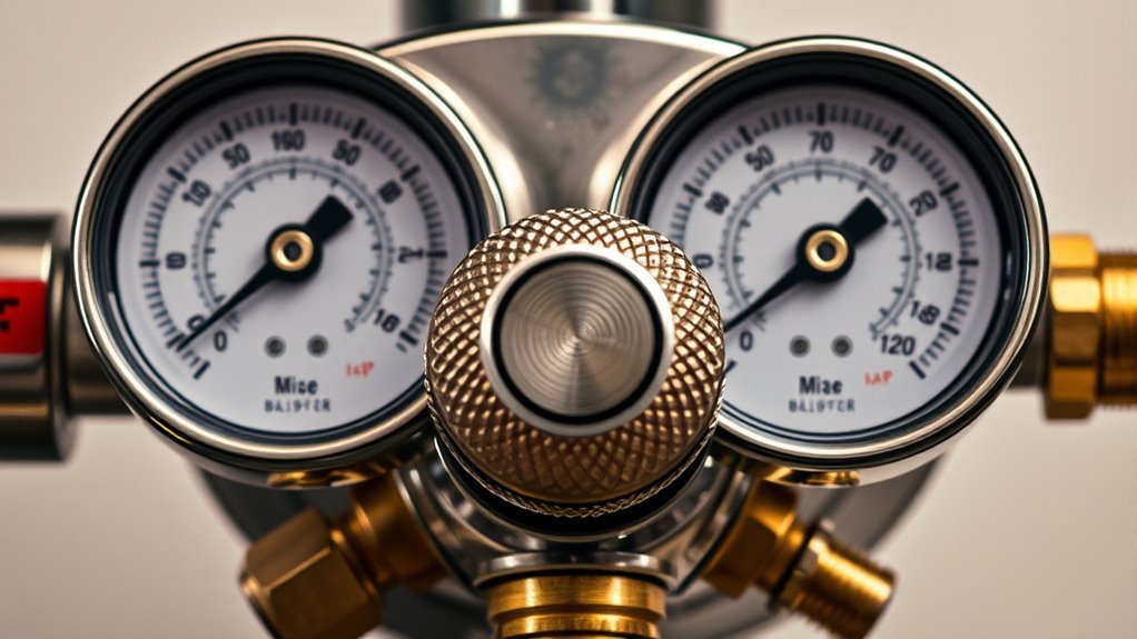
A welding gas regulator reduces high cylinder pressure to a safe, usable pressure for welding, cutting, or shielding gas delivery. It does this with a spring, adjusting screw, diaphragm, valve seat, and gauges that work together to keep outlet pressure steady as gas flows from the cylinder to your torch, MIG gun, or TIG torch.
Quick Answer
A welding gas regulator works by lowering high-pressure cylinder gas to a controlled outlet pressure. Turning the adjusting screw loads a spring against a diaphragm. As outlet pressure rises or falls, the diaphragm opens or closes an internal valve so gas delivery stays stable and safe.
Key Takeaways
- A regulator controls pressure; a flowmeter or flowgauge measures shielding gas flow in CFH or L/min.
- Single-stage regulators are simple and affordable, while dual-stage regulators hold steadier outlet pressure as cylinder pressure drops.
- Always match the regulator to the gas, cylinder connection, pressure rating, and welding process.
- Never use oil or grease on oxygen regulators, valves, hoses, or fittings.
- For oxy-fuel work, acetylene must stay within safe pressure limits, and flashback protection should be part of the setup.
At a Glance
| Time Required | 3-5 minutes to inspect, connect, leak check, and set pressure or flow before welding. |
| Difficulty | Beginner for basic checks; advanced repairs should be handled by a qualified regulator service technician. |
| Tools Needed | Correct gas regulator, correct cylinder, approved hose, leak-check solution or soapy water, and wrench only if the fitting requires one. |
| Cost | No added cost for routine checks if you already have the correct regulator; replacement cost depends on gas type, duty rating, and single-stage vs dual-stage design. |
Understanding the Basics of Welding Gas Regulators
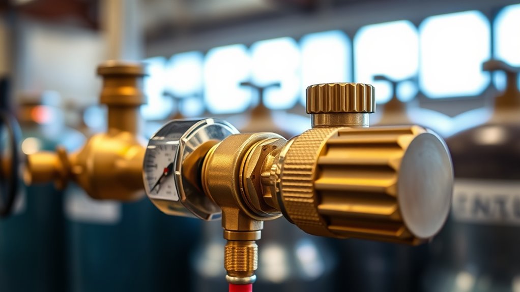
When you open a welding gas cylinder, the gas inside is under much higher pressure than your torch, hose, or shielding gas system can safely use. The regulator sits between the cylinder valve and the welding equipment. Its job is to reduce that cylinder pressure and hold the outlet side at the pressure or flow your process needs.
Most welding regulators have a cylinder pressure gauge, a delivery pressure gauge or flowmeter, an adjusting screw or knob, a spring, a diaphragm, and an internal high-pressure valve. Together, these parts help you control output pressure ranges without exposing your equipment to full cylinder pressure.
The exact setup depends on the process. Oxy-fuel welding and cutting usually use pressure regulators for oxygen and fuel gas. MIG and TIG shielding gas setups often use a regulator with a flowmeter or flowgauge so you can set gas flow in cubic feet per hour (CFH) or liters per minute (L/min).
Note: A pressure regulator and a flowmeter are related but not identical. The regulator reduces pressure. The flowmeter or flowgauge helps you set shielding gas flow. Many MIG and TIG units combine both in one body.
How a Welding Gas Regulator Works Step by Step
A welding regulator works through pressure balance. It does not simply let gas rush through. Instead, it opens and closes an internal valve as the low-pressure side changes.
- Gas enters from the cylinder. When the cylinder valve opens, high-pressure gas reaches the regulator inlet and the cylinder pressure gauge.
- The adjusting screw loads the spring. Turning the screw in increases spring pressure against the diaphragm. Backing it out reduces spring pressure.
- The diaphragm moves the valve. The diaphragm senses outlet pressure. When you call for more gas, outlet pressure drops, the diaphragm moves, and the internal valve opens.
- Gas fills the low-pressure chamber. Gas flows through the valve seat until the outlet side reaches the set pressure.
- The valve closes or throttles. When outlet pressure is high enough, the diaphragm moves back and the valve reduces flow or closes.
- The cycle repeats while you weld. Each time the torch, MIG gun, or TIG torch uses gas, the regulator responds to keep delivery steady.
This is why a good regulator matters. A worn seat, damaged diaphragm, loose fitting, wrong gas connection, or leaking gauge can cause unstable pressure, wasted gas, or unsafe operation.
Pressure Regulator vs. Flowmeter: What’s the Difference?
A pressure regulator controls the outlet pressure leaving the cylinder. This matters for oxy-fuel torches, cutting attachments, and any setup where a safe delivery pressure is required.
A flowmeter or flowgauge controls or displays how much shielding gas moves to the weld area. This matters for MIG and TIG welding, where too little gas can cause porosity and too much gas can create turbulence that pulls air into the shielding envelope.
| Device | What It Controls | Common Use |
| Pressure regulator | Outlet pressure, usually shown in psi, bar, or kPa. | Oxygen, acetylene, propane, and general pressure-controlled gas delivery. |
| Flowmeter regulator | Shielding gas flow, usually shown in CFH or L/min. | MIG and TIG welding with argon, helium, CO2, or mixed shielding gas. |
| Dual-flowmeter regulator | Two separate gas-flow outlets from one cylinder. | TIG welding with purge gas, dual-torch setups, or back purging stainless tube. |
The Role of Welding Pressure Regulators
Welding pressure regulators make gas delivery safer, steadier, and easier to control. Without a suitable regulator, high cylinder pressure could damage hoses, fittings, torches, or downstream equipment. For fuel-gas work, a regulator is not optional; fuel gas must be reduced through a suitable regulator before it is used through torches or similar devices.
A regulator also helps you repeat settings. Once you learn the right delivery pressure for a cutting tip, heating tip, brazing tip, or welding setup, you can return to that setting more reliably. For shielding gas, a flowmeter-style unit lets you adjust gas coverage based on the weld position, nozzle size, drafts, and procedure chart.
Good regulators are usually built from brass or other gas-compatible materials. A durable body, clean valve seat, clear gauges, and smooth adjustment all help the regulator hold steady pressure. A regulator built from high-quality brass can also resist wear better in normal shop use.
Components of Pressure Regulators
Most welding regulators use three core control parts:
- Adjusting screw or knob: Changes spring tension and sets the desired outlet pressure.
- Diaphragm: Senses outlet pressure and moves as pressure rises or falls.
- High-pressure valve or seat: Opens and closes to let more or less gas enter the low-pressure side.
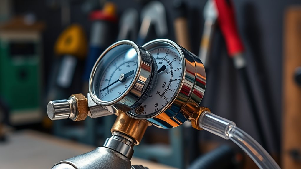
Regulators also use gauges or flow displays. The cylinder gauge shows supply pressure in the tank. The delivery gauge shows outlet pressure after reduction. A flowmeter shows gas flow to the weld area, often with a floating ball in a clear tube.
Safety Mechanisms in Regulators
Many regulators include safety features such as relief valves, protected gauges, and burst or relief devices. These parts are designed to reduce damage if pressure rises beyond the regulator’s intended range. However, they do not make a damaged regulator safe to keep using.
If a relief device vents, a gauge is damaged, pressure creeps upward with no gas flowing, or the adjusting screw behaves unpredictably, remove the regulator from service and have it checked by a qualified repair facility.
Warning: Do not repair regulator internals unless you are trained and authorized to do so. Regulators handle compressed gas, oxygen, fuel gas, and flammable mixtures. The wrong part, seal, lubricant, or cleaning method can create a fire, explosion, or leak hazard.
Single-Stage vs. Dual-Stage Regulators
When choosing a gas regulator, one of the biggest decisions is single-stage vs dual-stage. Both reduce pressure, but they respond differently as cylinder pressure drops.
| Type | Best For | Main Advantage | Main Limitation |
| Single-stage regulator | General shop use, short welds, light-duty setups, and budget-friendly systems. | Simple, affordable, and easy to adjust. | Outlet pressure can drift more as cylinder pressure changes. |
| Dual-stage regulator | TIG welding, lab-like accuracy, long welds, purge work, and applications needing stable delivery. | More stable outlet pressure as cylinder pressure falls. | Usually larger, heavier, and more expensive. |
If your work demands precision and consistency, a dual-stage regulator is usually the better choice. If you weld occasionally and can recheck the gauge during use, a single-stage regulator may be enough.
For shielding gas, using a flow meter tester at the torch or nozzle can help confirm that gas is actually reaching the weld area at the expected flow.
Products Worth Considering
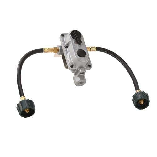
Allows removal of the empty cylinder for refill without interrupting propane supply; includes 2 of the 12-inch pigtails to connect the regulator to the propane tank or propane supply

PRECISE PRESSURE CONTROL: Dual-stage regulation provides consistent flow and optimal appliance performance.

Allows removal of an empty cylinder for refill without interrupting the propane supply
Essential Safety Features of Welding Regulators
Welding regulators are safety devices as much as control devices. Choose a regulator with clear gauges, a body rated for the gas and pressure, proper cylinder connections, and relief protection suitable for its design.
For oxy-fuel work, the regulator is only one part of the safety chain. The setup should also include approved hoses, check valves, and flashback arrestors where required by your equipment manufacturer, employer, or local rules. Flashback protection helps stop reverse flow or flame travel in oxygen and fuel-gas systems.
Warning: Never use oil, grease, oily gloves, or oily rags on oxygen cylinders, valves, regulators, hoses, or fittings. Oxygen can greatly accelerate fire, and contaminated oxygen equipment can become extremely dangerous.
Modern regulators may also include adjustable gas flow gauges that make it easier to tune shielding gas delivery. Even then, you should still verify flow at the torch when weld quality is critical.
How to Choose the Ideal Welding Regulator for Your Applications
Choose a welding regulator by starting with the gas, not the price. Oxygen, acetylene, argon, CO2, helium, propane, and mixed shielding gases can require different materials, pressure ranges, gauges, and cylinder connections.
Products Worth Considering

APPLICATION: The ARCCAPTAIN gas pressure regulator can be used with argon, helium, and carbon dioxide gas tanks.

Argon/CO2 Regulator with Flowmeter: Designed for MIG and TIG welding with argon, CO2, and argon/CO2 mixed gas tanks; CGA-580 inlet fits standard gas cylinders

CGA580 Inlet Connection: Welding gas regulators connects easily to argon and Co2 tanks, note that a CGA-320 adapter is required for use with Co2 cylinders. This product comes standard with the CGA-580 connector only
Application Requirements Assessment
Before buying or connecting a regulator, check these items:
- Gas type: Use only a regulator approved for that gas. Never adapt a fuel-gas regulator for oxygen or an oxygen regulator for fuel gas.
- Cylinder connection: The nut and fitting must match the cylinder valve. Do not force threads or use homemade adapters.
- Maximum inlet pressure: The regulator must be rated for the cylinder pressure it will see.
- Delivery range: The outlet pressure or flow range must fit your torch, welder, tip, or process chart.
- Duty level: Heavy shop use, long cuts, purge work, and production TIG often justify a higher-quality regulator.
If you are unsure about connection type or pressure rating, ask your gas supplier before connecting the regulator. For U.S. compressed gas cylinders, matching the correct CGA-style connection is part of safe compatibility.
Safety Features Evaluation
Look for a regulator with readable gauges, smooth adjustment, a clean inlet filter if the design uses one, intact threads, and no signs of impact damage. The regulator should adjust gradually, hold pressure without creeping upward, and return to zero when depressurized.
Regulators used for oxygen-fuel gas work should comply with applicable rules for approved apparatus. Standards such as ISO 2503 cover pressure regulators and pressure regulators with flow-metering devices for gas cylinders used in welding, cutting, and allied processes.
For more detailed regulator safety features, including relief devices and gauge styles, compare models carefully before buying. A regulator’s safety features matter more than a low price if the setup will be used often.
Compatibility Checks
Run these compatibility checks before use:
- Confirm the gas label on the cylinder before connecting anything.
- Confirm the regulator label matches the gas.
- Inspect the cylinder valve, regulator inlet, and threads for damage.
- Make sure washers, seats, or seals are present if that connection style requires them.
- Use the correct wrench only when the fitting is designed for wrench tightening.
- Never use Teflon tape on regulator-to-cylinder connections unless the manufacturer specifically calls for it. Many cylinder connections seal metal-to-metal or with a designed washer, not on the thread.
How to Connect and Check a Welding Gas Regulator Safely
Use this general sequence for a typical cylinder-mounted regulator. Always follow the regulator maker, gas supplier, and workplace procedure for your exact setup.
- Secure the cylinder upright. Chain or strap it so it cannot tip.
- Confirm the gas. Read the cylinder label, not just the cap color.
- Back out the adjusting screw. Turn it counterclockwise until spring pressure is released.
- Inspect the regulator. Look for cracked gauges, damaged threads, missing seals, oily contamination, or signs of impact.
- Briefly crack the cylinder valve if the gas and procedure allow it. Stand to one side, never in front of the outlet. Do not crack fuel-gas valves near sparks, flame, or welding work.
- Attach the regulator. Tighten only as required for that connection style.
- Connect the hose or flowmeter outlet. Make sure the hose is rated for the gas and pressure.
- Open the cylinder valve slowly. Stand to the side of the regulator, not in front of the gauges.
- Set pressure or flow. Turn the adjusting screw in slowly until the delivery gauge or flowmeter reaches the required setting.
- Leak check. Apply approved leak-check solution or soapy water to connections. Bubbles mean a leak.
- Correct leaks before welding. Close the cylinder, bleed pressure, fix the connection, and test again.
Pro Tip: Set shielding gas while gas is flowing, not while everything is closed. On a MIG welder, use the purge button if available. On TIG, use the torch gas valve or purge function so the flowmeter reading reflects real flow.
How to Read the Gauges
A standard two-gauge regulator usually has a high-pressure gauge and a low-pressure gauge.
- Cylinder pressure gauge: Shows pressure inside the cylinder. For gases stored as compressed gas, this helps estimate remaining gas. For liquefied gases such as CO2, pressure does not fall in the same simple way until the liquid is nearly gone.
- Delivery pressure gauge: Shows the pressure leaving the regulator and going to the hose or torch.
- Flowmeter tube: Shows gas flow. Read the ball at the correct point listed on the flowmeter, often the center of the ball.
If the delivery pressure slowly climbs when no gas is flowing, the regulator may have seat leakage, often called pressure creep. Stop using it and have it serviced or replaced.
Common Applications of Welding Gas Regulators
Welding gas regulators support several processes, but each process uses gas differently.
- Oxy-fuel welding and cutting: Oxygen and fuel-gas regulators reduce cylinder pressure to the working pressure needed for the torch, tip, and flame setting.
- MIG welding: A regulator with a flowmeter controls shielding gas such as argon/CO2, CO2, helium blends, or other approved mixes. Follow your wire, gas, and welder chart rather than guessing.
- TIG welding: Argon or argon/helium shielding gas is usually controlled with a flowmeter regulator. Stable flow helps protect the tungsten, arc, and weld puddle.
- Back purging: Stainless steel and some alloy tube work may use a second flowmeter to purge the back side of the weld.
- Heating and brazing: Oxygen and fuel-gas regulators provide controlled pressure for heating tips and brazing torches.
Warning: For acetylene, do not set delivery pressure above the safe limit listed by your equipment maker and applicable regulations. In U.S. OSHA rules, acetylene must not be used above 15 psig except in narrow approved cases.
Regular equipment inspections help keep regulators, hoses, fittings, and valves safe before the welding process starts.
Common Regulator Problems and What They Mean
Most regulator problems show up as leaks, unstable pressure, poor gas coverage, or gauge behavior that does not match the setting.
| Problem | Likely Cause | What to Do |
| Bubbles during leak test | Loose fitting, damaged seat, wrong washer, cracked hose, or damaged threads. | Close the cylinder, bleed pressure, fix the connection, and retest. Replace damaged parts. |
| Delivery pressure creeps upward | Internal seat leak or contamination. | Remove from service and have the regulator repaired or replaced. |
| Gauge does not return to zero | Damaged gauge or trapped pressure. | Depressurize safely. Replace or service the regulator if the gauge stays off zero. |
| Porosity in MIG or TIG welds | Low flow, excessive flow turbulence, drafts, clogged nozzle, or leaking hose. | Check flow at the torch, clean the nozzle, block drafts, and inspect hoses. |
Maintenance Tips You Can’t Afford to Ignore for Welding Regulators
Ensuring your welding gas regulator operates efficiently is vital for both safety and performance. Keep the regulator clean, dry, and protected from impact. Store it where gauges cannot be crushed and where oil, grease, grinding dust, and moisture will not contaminate it.
- Inspect gauges, lenses, threads, and fittings before every use.
- Leak check after connection and any time a cylinder or hose is changed.
- Keep oxygen regulators and fittings completely free from oil and grease.
- Replace cracked hoses, damaged washers, and questionable fittings immediately.
- Remove the regulator before moving cylinders unless the cylinder is secured on an approved cart designed for that purpose.
- Close cylinder valves when the work is finished or when the cylinder will sit unused.
- Schedule professional servicing if the regulator creeps, leaks, sticks, or shows damage.
Regular checks on shielding gas performance can also improve weld quality, especially when porosity or oxidation appears without an obvious machine-setting problem.
Safe Shutdown Sequence
Shutdown matters because pressure left inside the regulator can stress internal parts and hide leaks. Use this general sequence unless your equipment maker gives a different process:
- Close the torch valves or stop gas flow at the welder.
- Close the cylinder valve.
- Open the torch valve, purge button, or downstream valve briefly to release gas from the regulator and hose.
- Watch the gauges drop to zero.
- Back out the adjusting screw until spring pressure is released.
- Close the torch or downstream valve.
- Store the hose and regulator where they will not be damaged.
If you are removing a regulator from a cylinder, close the cylinder valve first and release gas from the regulator before loosening the connection.
Frequently Asked Questions
How does a welding gas regulator work?
A welding gas regulator reduces high cylinder pressure to a controlled outlet pressure. The adjusting screw loads a spring, the spring moves a diaphragm, and the diaphragm opens or closes an internal valve as outlet pressure changes. This keeps gas delivery steadier while you weld.
How do I check if a gas regulator is working?
Secure the cylinder, back out the adjusting screw, connect the regulator, open the cylinder slowly while standing to the side, set the pressure or flow, and leak check every connection. The regulator should adjust smoothly, hold a steady setting, and drop to zero when depressurized.
What are common regulator problems?
Common problems include leaking fittings, cracked gauges, damaged threads, pressure creep, unstable outlet pressure, clogged flowmeters, and gauges that do not return to zero. Any regulator with pressure creep, impact damage, or unknown contamination should be removed from service.
Which gas regulator should be closed first in gas welding?
For shutdown, follow your torch and regulator manufacturer’s sequence. In general, close cylinder valves, bleed pressure from the lines and regulator, watch the gauges drop, then back out the adjusting screws. Many oxy-acetylene procedures close the acetylene torch valve first to extinguish the flame, then oxygen, before closing cylinder valves and bleeding the system.
Can I use the same regulator for argon and CO2?
Only if the regulator is rated and fitted for that gas or gas mix. Many argon/CO2 shielding gas regulators are designed for common MIG and TIG mixes, but straight CO2 may require the correct CGA connection and a regulator suited for CO2 service. Always check the label and manufacturer instructions.
Why does my welding gas regulator freeze?
Freezing can happen when gas expands quickly through the regulator, especially with high flow, cold conditions, or CO2 service. Moisture can make it worse. Use the correct regulator for the gas, avoid excessive flow, and ask your gas supplier about heaters or heavy-duty equipment if freezing repeats.
Conclusion
A welding gas regulator may look like a small part of your setup, but it controls one of the most important parts of the job: safe, steady gas delivery. The regulator reduces cylinder pressure, the gauges show what is happening, and the adjusting screw lets you set the pressure or flow your process needs.
For the best results, match the regulator to the gas, use the correct cylinder connection, check for leaks, protect oxygen equipment from oil and grease, and shut the system down correctly. If a regulator leaks, creeps, sticks, or shows damage, do not gamble with it. Remove it from service and replace or repair it through a qualified source.
Sources
- eCFR 29 CFR 1910.253, Oxygen-fuel gas welding and cutting — supports acetylene pressure limits, approved apparatus, cylinder handling, oxygen cleanliness, valve closing, and regulator removal safety.
- Health and Safety Executive, Safety in gas welding, cutting and similar processes — supports portable oxy-fuel gas equipment hazard awareness and safe-use precautions.
- ISO 2503, Gas welding equipment pressure regulators — supports standards context for regulators and flow-metering devices used with welding, cutting, and allied gas cylinders.