If you run a plasma torch, the electrode is your current carrier and arc initiator. It’s a copper body with a hafnium insert, and it won’t last forever. Expect 1–2 hours of continuous cutting or roughly 200–300 pierces before pit depth exceeds 1/16 inch. Wear accelerates with improper amperage, wet or dirty gas, and poor setup. Inspect frequently, log your pierces, and match amps to material thickness.
Quick Answer
- A plasma cutter electrode typically lasts 1–2 hours of continuous cutting or 200–300 pierces.
- Replace it when the hafnium pit depth exceeds 1/16 inch (1–1.6 mm).
- The biggest wear accelerators are excess amperage, dirty or wet gas, and skipped maintenance.
- Proper maintenance can extend electrode life by 20–30%.
- Match your amperage to material thickness and keep gas clean and dry at manufacturer-specified flow rates.
Understanding the Electrode’s Role in Plasma Cutting
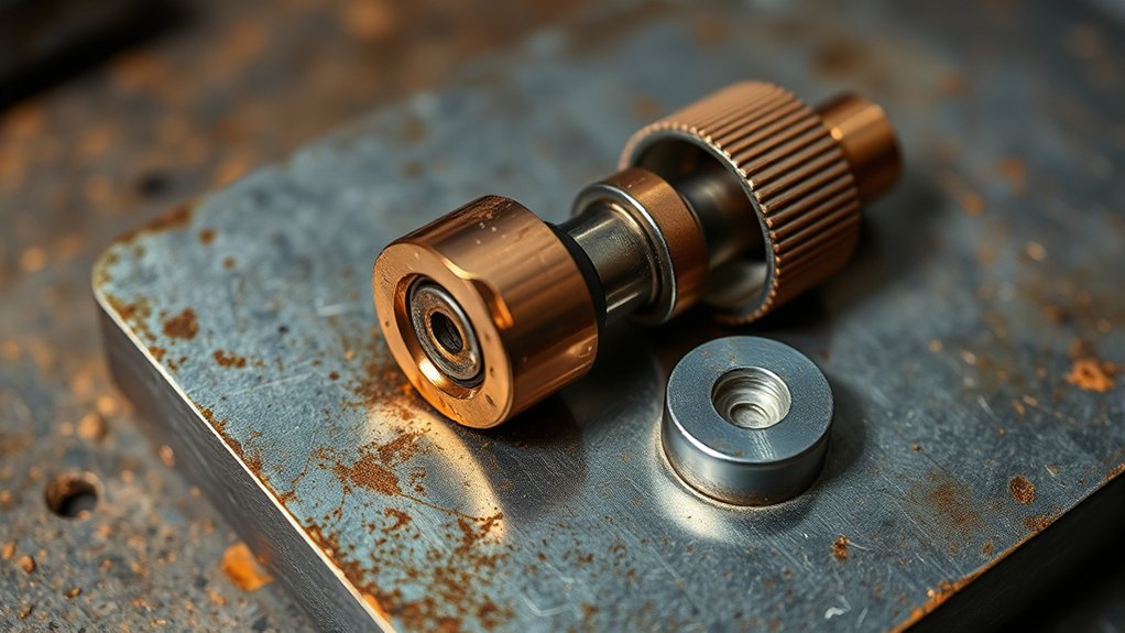
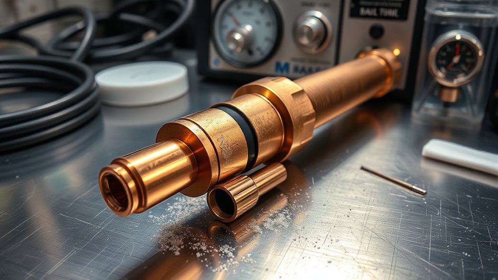
The electrode is small, but it does the most critical job in the torch. The copper body carries current with minimal resistance, while the hafnium insert holds a negative DC charge that establishes and sustains the plasma arc.
This design conducts current at ignition and throughout steady-state cutting, producing a stable, focused plasma arc through the nozzle orifice.
Performance is measurable. Expect 1–2 hours of continuous cutting or about 200–300 pierces, depending on amperage, duty cycle, and workpiece thickness.
Expect 1–2 hours cutting or 200–300 pierces, depending on amperage, duty cycle, and material thickness.
Use a simple wear criterion: replace the electrode when hafnium pit depth exceeds 1/16 inch (1–1.6 mm). Past that point, arc attachment degrades, arc voltage rises, and double-arcing can damage the nozzle.
Clean and inspect at defined intervals. Consistent maintenance can extend electrode life by 20–30% and cut consumable costs. Also check nozzle bore condition and swirl ring integrity, since gas flow dynamics and alignment directly affect arc stability.
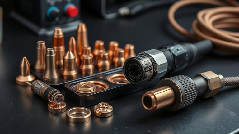
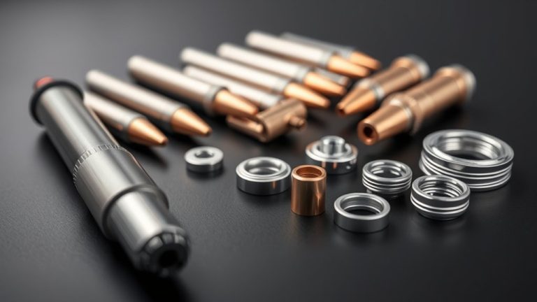
Electrode Materials and Construction
Specify a copper body for high conductivity and thermal transfer, paired with a hafnium insert to stabilize the arc and resist erosion. Verify that the heat dissipation design meets your duty-cycle and amperage requirements to limit tip pitting. Inspect wear data to confirm small, even pits under rated settings, and schedule replacement before pit depth exceeds acceptable limits.
Copper Body, Hafnium Insert
Precision starts at the tip. A copper body paired with a hafnium insert is the standard plasma cutter electrode because it balances conductivity, arc stability, and heat tolerance.
Copper provides low-resistance current flow, minimizing voltage drop and heat generation. Hafnium brings a high melting point and superior electron emission, which initiates and sustains a tight, stable plasma column. Together, they survive tip temperatures exceeding 3,000°F under duty-cycle conditions.
Track wear quantitatively. The arc erodes the hafnium and forms a pit. Replace the electrode when pit depth reaches 1/16 inch (1–1.6 mm) to maintain cut quality and prevent nozzle damage. Inspect routinely for pits and discoloration.
Heat Dissipation Design
Two design priorities govern electrode heat dissipation: high conductivity for low I²R losses, and robust hot-spot management at the insert.
The copper body handles thermal conductivity, while the hafnium (or tungsten) insert tolerates temperatures above 3,000°F at the tip. Good heat management stabilizes the electrode, ensures consistent arc initiation, and extends service life.
- Specify copper alloys with high k-values and low resistivity to drain heat from the insert efficiently.
- Use optimized insert geometry and fit-up to spread current density and limit pit formation from plasma erosion.
- Employ internal cooling paths that reduce thermal resistance to the coolant and lower tip temperature gradient.
- Set inspection intervals to track wear patterns and replace before crater growth accelerates heating and instability.
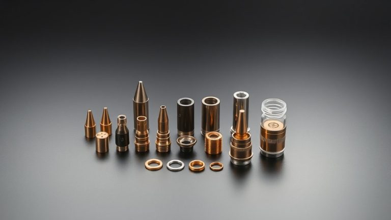
How the Electrode Interacts With Other Torch Consumables
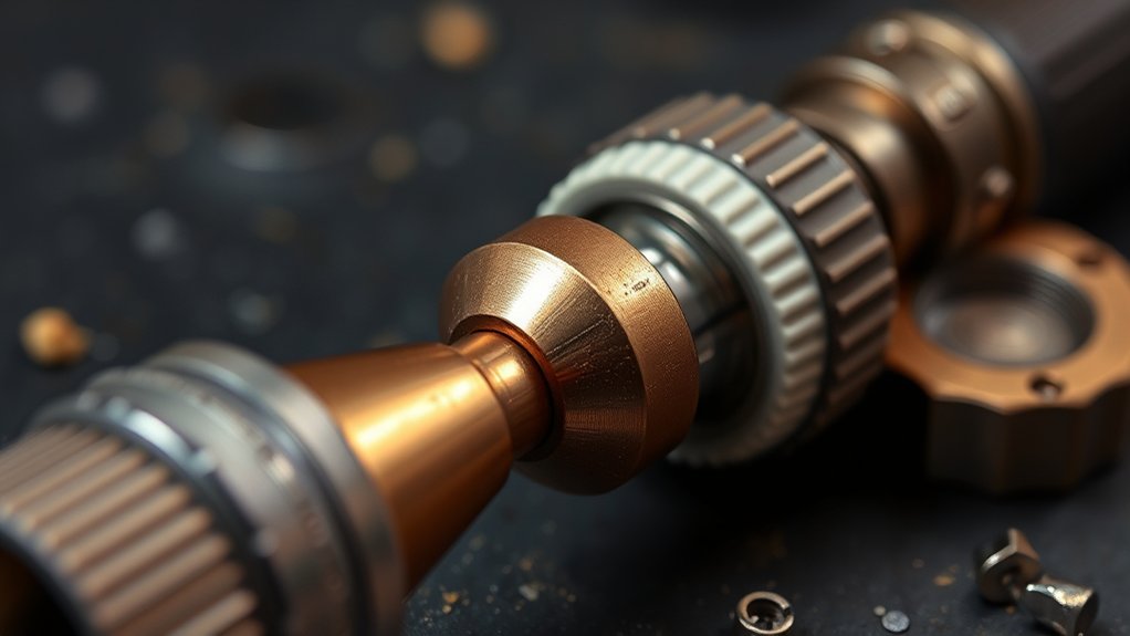
The electrode doesn’t work in isolation. Swirl ring gas dynamics stabilize the arc and reduce pitting by maintaining clean, dry, high-velocity flow per manufacturer specs. Nozzle orifice alignment keeps the arc centered, which limits arc wander, overheating, and premature nozzle wear. The shield cap manages heat through gas cooling and duty-cycle control, protecting both the electrode and nozzle from premature failure.
Swirl Ring Gas Dynamics
The swirl ring is easy to overlook, but its gas dynamics control how the electrode survives and how the arc performs.
The ring meters gas flow, creates angular momentum, and forms a uniform sheath around the arc column. That uniformity stabilizes plasma temperature, maximizes heat extraction from the electrode, and limits pitting.
- Verify gas flow: Measure inlet pressure and volumetric rate against OEM specs. Inconsistent flow drives arc wander and accelerates wear.
- Inspect ring integrity: Check for micro-cracks, warpage, or blockage. Defects disrupt circumferential distribution and raise electrode tip temperature.
- Maintain cleanliness: Remove spatter and oxides from ports. Fouling reduces the cooling boundary layer and shortens lifespan.
- Monitor arc signatures: Track voltage ripple and cut kerf symmetry. Rising ripple or asymmetry signals degraded swirl and impending electrode failure.
Nozzle Orifice Alignment
When the nozzle orifice aligns concentrically with the electrode tip, the arc column stays axially symmetric. This maximizes energy density and minimizes radial heat flux into the consumables. Misalignment skews the jet, producing uneven cuts and higher dross.
Verify fit, torque to spec, and confirm the orifice is round and centered. Any ovality or nicks distort the arc profile and shorten component life. Maintain correct pierce height and torch-to-work distance, since out-of-spec standoff amplifies edge loading and accelerates wear.
| Checkpoint | Data/Action |
|---|---|
| Orifice geometry | Round within tolerance; no burrs |
| Concentricity | Tip-to-orifice offset ≤ manufacturer spec |
| Arc stability | Monitor voltage ripple; minimize fluctuation |
| Pierce height | Set per thickness chart; verify repeatability |
| Nozzle wear | Track kerf quality; replace at threshold |
Shield Cap Heat Management
Once orifice alignment is set, manage heat at the shield cap to keep the electrode within its thermal envelope. The shield cap buffers radiant and convective load on the nozzle and stabilizes gas flow, protecting electrode life.
- Verify cap integrity: Inspect threads, vents, and face for nicks, warping, or clogging. Replace at the first sign of deformation to preserve gas symmetry and cooling efficiency.
- Maintain clean flow paths: Remove spatter and oxide from ports. Contamination elevates electrode temperature and accelerates wear.
- Use spec’d gas pressure and flow: Adhere to OEM flow (±5%) to sustain boundary-layer cooling around the electrode.
- Monitor thermal indicators: Track cut current, duty cycle, and electrode pit depth. A rising pit rate signals declining heat control and cap durability.
Typical Electrode Lifespan and Performance Indicators
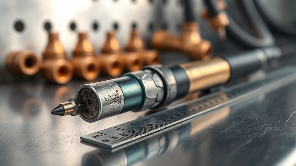
Even under ideal conditions, a plasma cutter electrode typically delivers 1–2 hours of continuous cutting or roughly 200–300 pierces, depending on amperage and material thickness. Track electrode efficiency by logging pierce count, total arc-on time, and cut quality metrics (kerf width, dross, edge bevel).
When performance drifts — wider kerf, more dross, arc instability — inspect the electrode.
Use a go/no-go approach: replace when pit depth at the hafnium insert reaches 1/16 inch (1.6 mm). Small, even pits indicate normal wear. Deep, conical pits signal imminent failure and risk of nozzle damage.
Lower amperage (30–50 A) generally slows erosion compared to 90+ A operations, so align consumable life estimates with your set current and duty cycle.
Keep gas clean and dry, and verify coolant flow rate and temperature. Documented best practice shows these controls can extend service life by 20–30%, stabilizing the arc and preserving dimensional tolerances.
Operating Factors That Influence Wear and Longevity
Electrode life is inherently limited, but your operating choices largely determine whether you reach the upper end of the 1–2 hour, 200–300 pierce window. The dominant variables are heat load, gas quality, and how consistently you maintain components between runs.
Excess current concentrates thermal stress at the emissive insert and accelerates pitting. Clean, dry gas at the correct flow rate stabilizes the arc column and minimizes contaminant-driven erosion.
- Match current to the cut. At 90+ amps, expect accelerated wear. At 30–50 amps, life extends substantially. Avoid oversetting amperage for thin stock.
- Control gas. Use clean, dry gases and verify ideal flow rates. Inadequate purity or flow elevates oxidation and micro-pitting.
- Maintain routinely. Clean the electrode after each use. Documented programs show 20–30% life gains.
- Inspect methodically. Replace when pits deepen or become uneven. Small, uniform pits indicate acceptable wear and preserve kerf quality and pierce reliability.
Best Practices for Setup, Amperage, and Gas Quality
Set up your torch to the standard, then let data guide every adjustment. Dial amperage to the cut class (30–50 A for thin, 60–80 A for medium, 90+ A for thick) to limit heat load on the emissive insert. Verify a pierce height of 3.8 mm before descent to prevent spatter impact. Stabilize the arc with clean, dry process gas at manufacturer-specified flow.
Match current to material and speed so arc voltage stays within the machine’s window. Overcurrent accelerates tip erosion. Undercurrent destabilizes the column.
Match current to material and speed to keep arc voltage in range; overcurrent erodes tips, undercurrent destabilizes the column.
Use consistent cutting technique. Maintain standoff, hold travel speed that yields a near-vertical kerf, and pierce at height before descending to cut height. Specify gas flow by the data plate, then confirm with a calibrated meter. Adjust for nozzle size and duty cycle.
Purge lines to eliminate moisture and oil. Contaminants raise arc noise and pitting. Monitor arc sound and dross signature as real-time indicators. When deviations appear, correct amperage or gas flow first to protect the electrode and recover cut quality.
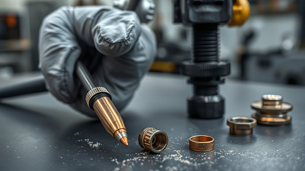
Maintenance, Cleaning, and Storage Guidelines
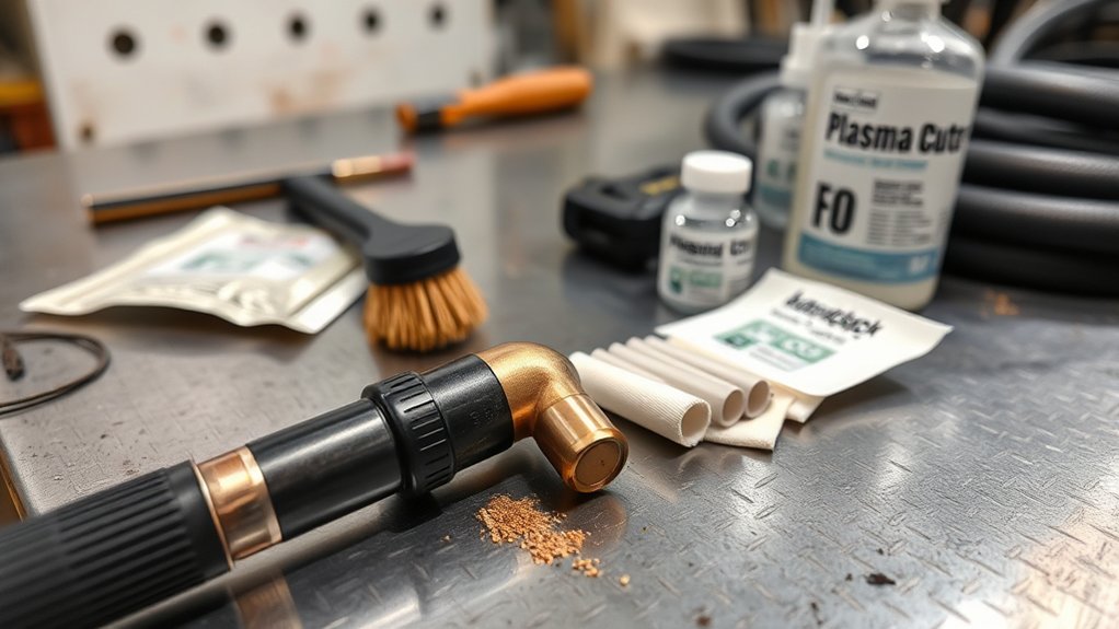
Cutting performance depends on setup, but durability hinges on disciplined care. Inspect electrodes after each use and retire any with pits deeper than 1/16 inch (1–1.6 mm). Clean with a soft cloth and mild soap, rinse with clean water, and dry completely to prevent moisture-induced pitting.
- Cleaning: Wipe with a lint-free cloth and mild detergent, rinse with deionized water, then air-dry or towel-dry until no residual moisture remains. Avoid abrasives that alter tip geometry.
- Storage: Place fully dried electrodes in sealed containers with fresh silica gel. Label date, lot, and last service hours. Store at 10–27°C in a low-humidity cabinet (below 40% RH).
- Handling: Use nitrile gloves to limit skin oils. Cap consumables immediately after cooldown. Segregate new and used parts to prevent mix-ups.
- Operation: Maintain specified gas flow and avoid rapid cycling (frequent starts/stops) to reduce thermal shock and arc erosion.
Document inspections and replacements to maintain traceability and consistent cut quality.
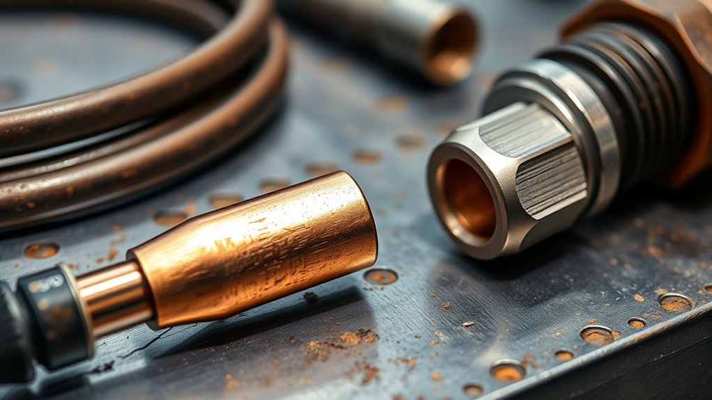
Identifying Wear Patterns and When to Replace
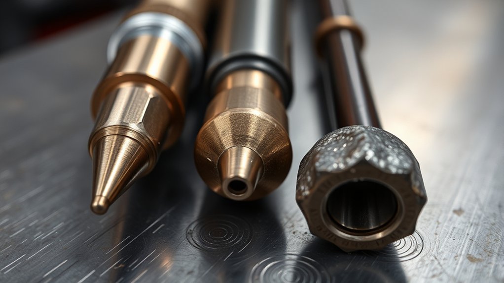
With cleaning, storage, and handling under control, shift your inspection to measurable wear indicators. After each cutting sequence, document wear patterns, arc behavior, and pierce counts.
Normal wear presents as small, even pits at the emitter. Use a depth gauge or feeler to verify pit depth. Once pits exceed 1/16 inch (1–1.6 mm), that’s a hard replacement threshold. Hypertherm’s plasma consumables guide outlines manufacturer-specific wear criteria worth bookmarking alongside your torch manual.
Normal wear shows small, even emitter pits — replace once depth exceeds 1/16 inch (1–1.6 mm).
Track duty metrics to confirm replacement timing. Expect an electrode lifespan of roughly 1–2 hours of continuous cutting or 200–300 pierces, adjusted for amperage and material thickness.
Before that limit, watch for performance triggers: unstable arc start, increased dross, wider kerf, or inconsistent penetration.
Inspect the geometry visually. Rough or melted edges, elliptical pit growth, or discoloration (a darkened or bluish halo) indicate overheating and call for immediate replacement to protect nozzle integrity and cut quality. When in doubt, retire the part early to stabilize process capability and prevent downstream defects.
Cost Planning and Strategies to Maximize Value
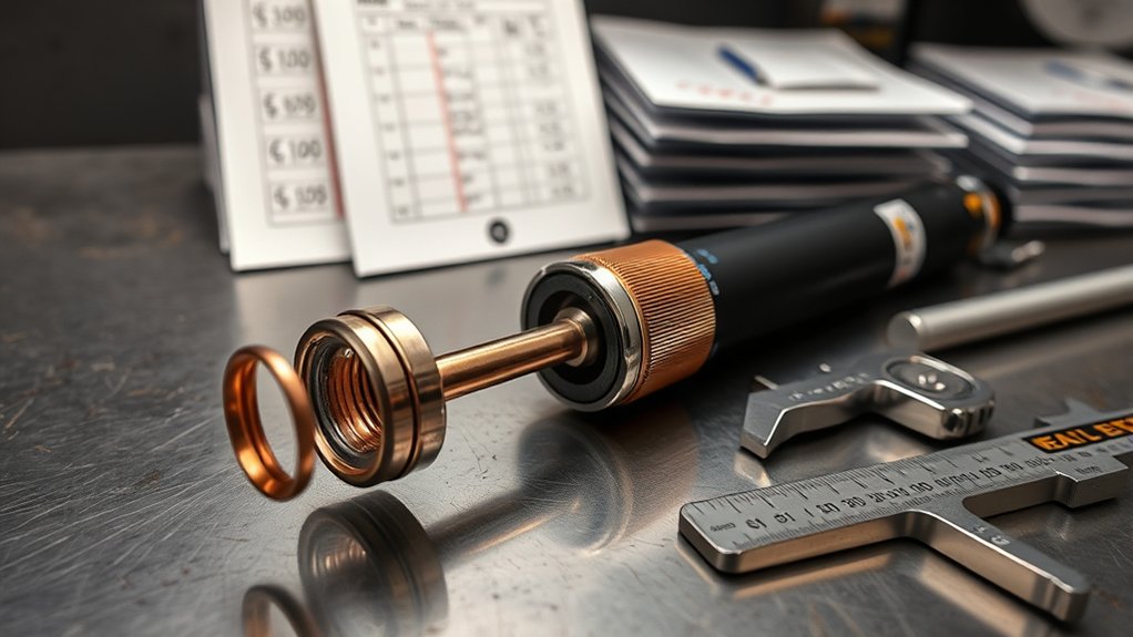
Consumables are an inevitable cost, but electrode spend is a controllable line item. Forecast usage against duty metrics and enforce cost controls.
Standardize your cost model. At $20–$50 per electrode, busy shops often land at $500–$1,000 per year. Track burn hours, pierce counts, and amperage to predict consumption and set reorder points with safety stock.
- Quantify demand: Calculate electrodes per 100 pierces or per shift, then budget quarterly. Use actuals to refine forecasts and prevent rush buys.
- Apply bulk purchasing: Leverage tiered pricing and consolidated orders to cut unit cost. Validate supplier lead times, warranty terms, and lot traceability.
- Enforce maintenance scheduling: Inspections and nozzle/torch cleanings can extend life 20–30%, reducing replacements and stabilizing inventory turns.
- Optimize practice: Train operators on correct arc starts, cooling cycles, and handling. Higher-quality electrodes often outlast cheaper alternatives and deliver more consistent performance.
Audit monthly, compare plan versus actual, and adjust.
Frequently Asked Questions
Can I Mix Electrode Brands With Different Torch Systems?
No. Don’t mix electrode brands across different torch systems. Verify electrode compatibility via OEM part numbers, tolerances, and metallurgy. Mixing degrades arc stability and consumable life. Follow manufacturer standards and validate with dimensional checks and controlled cut-quality tests.
Are There Signs of Counterfeit Electrodes to Watch For?
Yes. Inspect packaging for misprints, inconsistent lot numbers, missing certifications, and poor seals. Measure dimensions, weight, and material composition. Deviations from spec indicate counterfeit materials. Monitor arc stability, erosion rate, and cut quality versus OEM specifications.
How Should I Dispose of Spent Electrodes Responsibly?
Dispose of spent electrodes through approved recycling options or an RCRA-compliant hazardous waste facility. Segregate copper and tungsten parts, label containers, and document manifests. Don’t landfill. Verify local regulations, TCLP thresholds, and vendor take-back programs to ensure compliant, traceable handling.
Do Ambient Temperature or Humidity Affect Electrode Performance?
Yes. Temperature shifts alter arc stability, and humidity promotes oxidation and micro-contamination. Preserve electrode longevity by controlling storage climate, adhering to manufacturer dew-point limits, and validating performance through periodic arc-voltage and cut-quality checks.
What Certifications Indicate Quality or Safety Compliance for Electrodes?
Look for ISO 9001 (quality assurance), ISO 14001, ISO 45001, CE marking, UL/CSA listing, and RoHS/REACH compliance. These indicate controlled manufacturing, safety validation, and restricted-substances compliance.
Conclusion
You now know what the electrode does, how long it lasts, and when to swap it — before that hafnium pit exceeds 1/16 inch and your arc starts behaving like a lawn sprinkler. Match amperage to thickness, keep gas clean and dry per spec, and log your pierces. Target the 200–300 range, inspect on schedule, and buy in bulk. Do this consistently and your torch will hold tolerance, your cuts will stay clean, and your consumable costs will stay predictable.