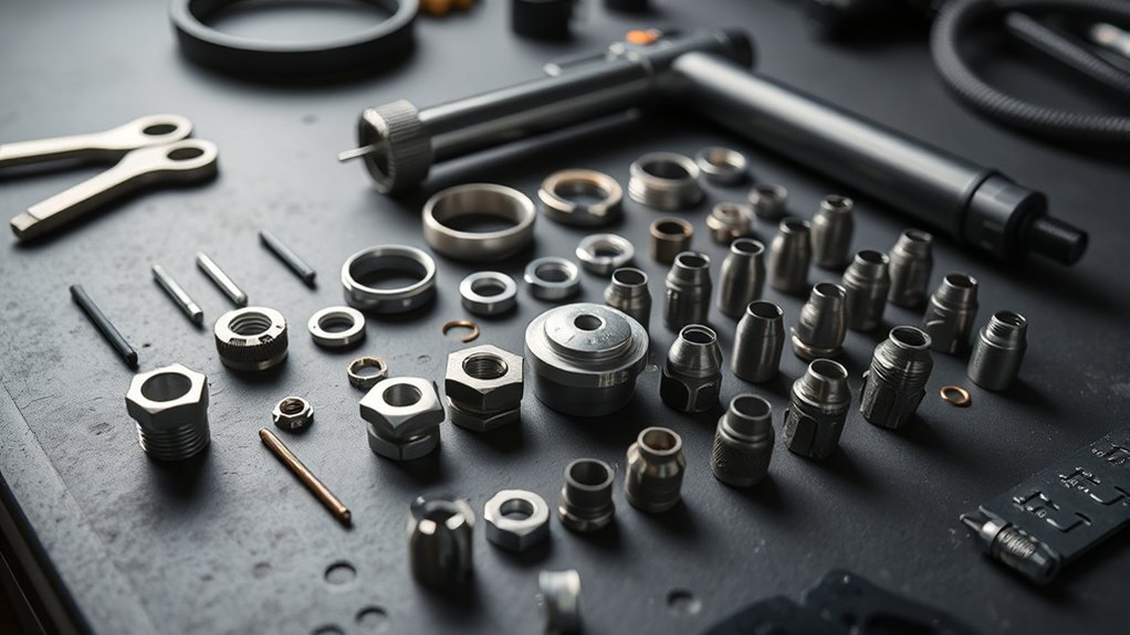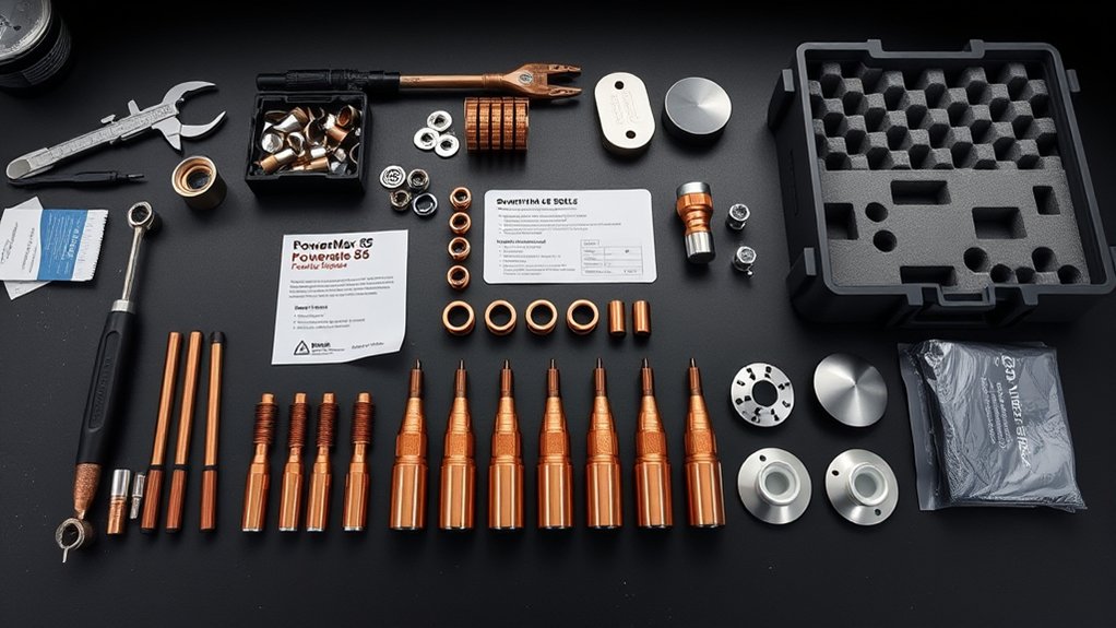
Plasma cutter consumables control how the arc starts, narrows, cools, and reaches the workpiece. When the correct parts are clean, matched, and installed properly, the torch produces a narrow kerf and steady edge. When one part wears or the gas supply changes, you may see bevel, dross, misfires, or rapid nozzle damage. The key is to inspect by condition and follow the limits in your exact torch manual rather than relying on a universal replacement schedule.
Quick Answer
Traditional plasma cutter consumables include an electrode, nozzle, swirl ring, retaining cap, and shield or deflector. Newer torches may use a single-piece cartridge instead. Inspect parts before each shift, replace damaged or out-of-limit components, and always match the consumable, current, gas setting, and process to the torch’s cut chart.
Key Takeaways
- Identify your exact torch and consumable platform before ordering or installing parts.
- Replace consumables by measured wear, visible damage, cut quality, fault history, and the limits in the operator’s manual—not by a universal number of hours.
- A round nozzle orifice, sound swirl ring, correct electrode condition, clean gas path, and properly seated cap are all needed for a stable arc.
- Clean, dry air, correct dynamic pressure, proper standoff, and correct pierce settings can extend life more than changing brands.
- Coolant, O-ring lubricant, tightening method, and electrode limits are model-specific.
At a Glance
| Time Required | About 5–10 minutes for a routine external inspection and consumable change |
| Difficulty | Easy when the torch manual and correct parts are available |
| Tools Needed | Operator’s manual, bright inspection light, clean lint-free cloth, and any gauge or installation tool specified by the manufacturer |
| Cost | Varies by torch, amperage, process, brand, and whether the system uses separate parts or a cartridge |
Warning: Turn off and isolate input power according to the manufacturer’s instructions before removing torch parts. Let the torch cool, close or isolate the gas supply when required, and wear suitable eye, face, hand, hearing, and flame-resistant protection. Plasma cutting can expose you to electrical shock, UV radiation, hot metal, fire, noise, and hazardous fumes. Use adequate ventilation and follow applicable hot-work procedures.
What Are Plasma Cutter Consumables?
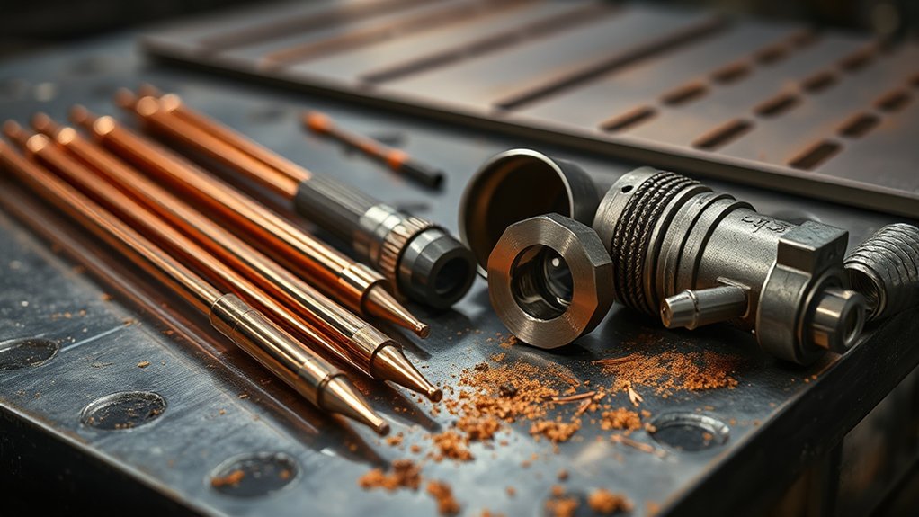
Plasma cutter consumables are the replaceable torch parts exposed to the arc, hot gas, molten metal, and repeated starts. They shape and stabilize the plasma jet while protecting the torch body. On a traditional torch, the stack may include an electrode, nozzle, swirl ring, retaining cap, and shield or deflector.
Those names are not universal. Some manuals call the nozzle a tip, the retaining cap a cup, or the shield a drag shield. Mechanized and liquid-cooled torches can also contain inner and outer retaining caps, water tubes, or additional gas-control parts.
Newer systems may not have a user-assembled stack at all. For example, Hypertherm Powermax SYNC systems use a single-piece cartridge that replaces the traditional five-part arrangement. Identify the exact torch model and platform before applying any replacement limit in this guide.
The operator’s manual—not a universal hour estimate—is the final authority for consumable combinations, wear limits, gas settings, tightening, and replacement.
The Traditional Consumable Stack and How It Works
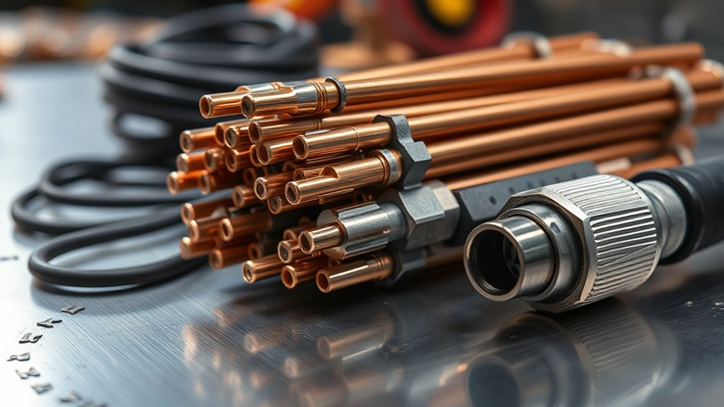
When the traditional stack is assembled correctly, it creates a controlled path for electricity and gas. The electrode supports the arc. The nozzle constricts and aims it. The swirl ring controls gas rotation. The retaining cap holds the parts in position, and the shield protects the nozzle while managing outside gas flow or standoff.
| Part | Main Job | Common Wear Sign |
|---|---|---|
| Electrode | Carries current and anchors the arc at an emissive insert, often hafnium | Pit or crater beyond the manual’s limit, uneven erosion, or damage on the rear surface |
| Nozzle or tip | Constrains and directs the plasma arc | Oval, enlarged, nicked, or chamfered orifice; heavy bonded spatter |
| Swirl ring | Directs gas through angled holes to center and stabilize the arc | Cracks, heat damage, deformation, dirt, or blocked gas holes |
| Retaining cap or cup | Holds components in the correct position and may route gas or coolant | Cracks, burns, damaged threads, distorted seating surfaces, or leaking seals |
| Shield or deflector | Protects the nozzle and may set standoff or direct shield gas | Blocked holes, cracks, impact damage, severe erosion, or spatter that cannot be removed safely |
The parts must belong to the same approved family and process. A cutting nozzle, gouging nozzle, fine-cut nozzle, shield, and electrode may look similar but have different gas passages and current ratings. Mixing them can produce hard starts, double arcing, wide kerfs, excessive bevel, or torch damage.
Note: Do not assume the cap needs wrench torque. Many handheld systems specify finger-tight installation. Overtightening can distort internal parts, while a loose or cross-threaded cap can prevent correct seating or defeat a torch safety circuit.
Electrode Types, Wear Signs, and Replacement
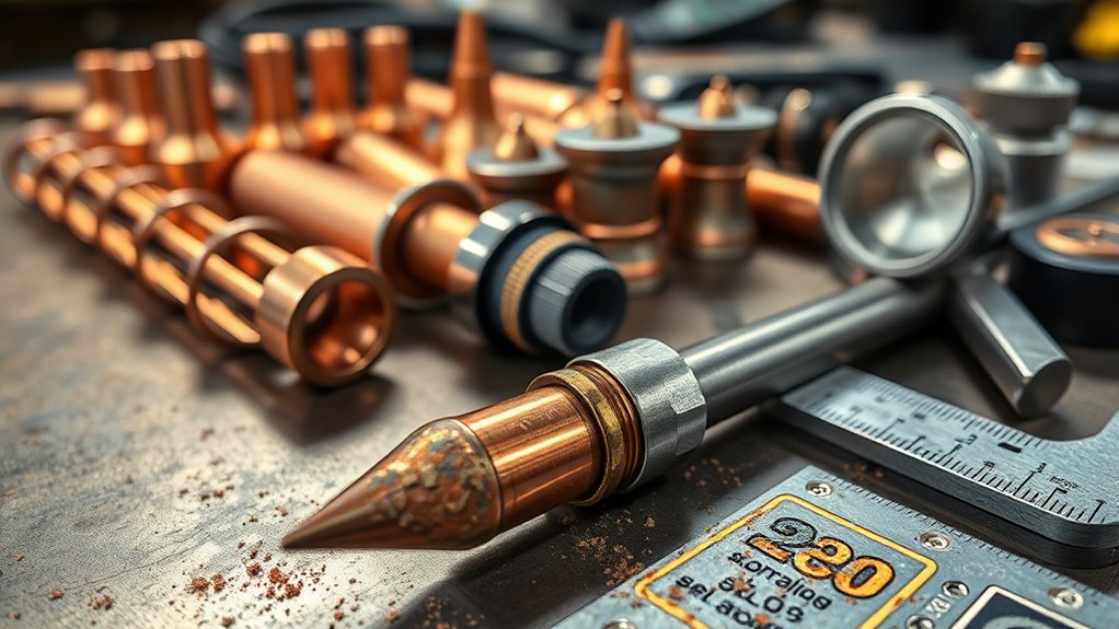
A common air-plasma electrode has a copper body and a small hafnium insert. Copper carries heat away from the front of the torch, while the insert provides the point from which the arc is emitted. Other torch designs can use different electrode materials or geometries.
As the insert erodes, a pit develops. The acceptable depth is model-specific. In its traditional Powermax maintenance guidance, Hypertherm says the hafnium pit should be no greater than 1.6 mm, or 1/16 inch. That is a useful example, not a universal rule. Some torches specify a shallower limit or use a different inspection method. Check the drawing and wear limit in your operator’s manual before measuring.
Replace the electrode when any of these conditions applies:
- The pit reaches the limit listed for the torch.
- The pit is badly off-center or the insert is cracked or missing.
- The rear of the electrode shows abnormal pitting, burning, or poor contact.
- The torch begins misfiring and the nozzle, gas supply, work connection, and setup have been checked.
- A cartridge system reports end of life or shows the manufacturer’s replacement indicator.
Do not continue cutting until the insert is consumed. A failed electrode can allow the arc to attach where it should not, damaging the nozzle or electrode seat inside the torch.
Many manufacturers recommend inspecting the electrode and nozzle as a pair because both experience wear during starts and cutting. Miller also recommends replacing the tip and electrode together for best cut quality on the systems covered by its guidance. Follow your torch manual if it gives a different pairing rule.
Nozzles: Sizing, Kerf Control, and When to Replace Them
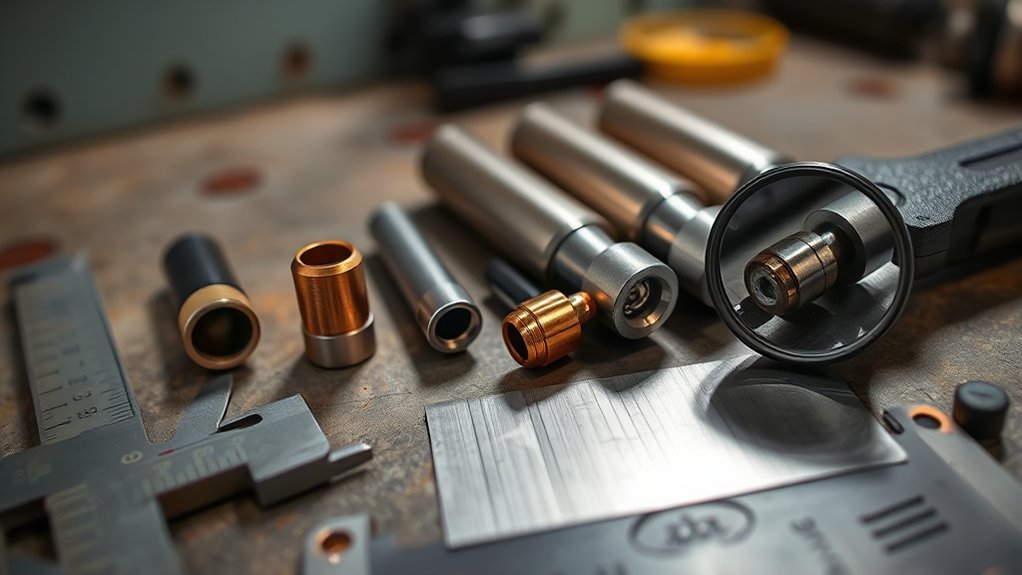
The nozzle constricts and directs the arc. Its orifice size and internal shape are designed for a specific torch, process, and current range. A smaller cutting nozzle can support a narrow kerf at its intended current, while gouging consumables produce a broader arc for metal removal.
Do not choose a nozzle from amperage alone. Use the manufacturer’s cut chart to match:
- Torch and consumable family
- Cutting, gouging, marking, fine-cut, drag, or mechanized process
- Material type and thickness
- Amperage and gas type
- Pierce height, cut height, delay, and travel speed
Inspect the orifice under a bright light. A serviceable opening should match the shape shown in the manual. Replace the nozzle when the opening becomes oval, enlarged, notched, or visibly chamfered, or when bonded spatter damages the exit face.
Do not force a drill bit, wire, file, torch-tip cleaner, or abrasive into the orifice unless the manufacturer specifically permits it. Enlarging or scratching the precision opening can make a usable nozzle cut worse.
If kerf width suddenly grows, first inspect the nozzle opening—but also check torch height, pressure, travel speed, and torch angle before assuming the nozzle is the only cause.
Products Worth Considering

[Achieve Precise Cuts] PT31 Plasma Cutting Consumables – Your Essential Tool for Efficient Cutting! Whether you're working with sheet metal, steel, or any other material, superior cutting performance ensure clean, accurate, and smooth cuts.

20pcs Plasma Tips Nozzle Extended Ref No: 18866L

Fit for: AG-60 AG-60P SG-55 WSD-60 Plasma cutter torch head
Swirl Rings, Retaining Caps, and Shields: Roles and Care
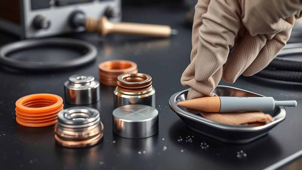
The swirl ring, retaining cap, and shield may last through several electrode and nozzle changes, but they still require inspection. Small cracks, blocked passages, impact damage, or incorrect seating can disturb gas flow and shorten the life of the entire stack.
Roles in Arc Control
| Control Element | Arc-control Function |
|---|---|
| Swirl ring | Shapes rotating gas flow to help center the arc and manage heat at the nozzle. |
| Retaining cap | Keeps approved parts seated and may route gas or coolant, depending on the torch. |
| Shield or deflector | Protects the nozzle, manages external flow, and may maintain drag-cutting standoff. |
| Gas path | Provides the specified clean flow needed to form the arc and remove molten metal. |
| Coolant path | Removes heat only on liquid-cooled systems and depends on approved coolant, seals, flow, and filtration. |
Inspection and Maintenance
Check swirl-ring holes for blockage or deformation. Replace a ring that is cracked, burned, warped, chipped, or damaged around a gas port. Do not push sharp tools through precision holes unless the manual gives a cleaning method.
Check retaining caps and cups for burns, cracks, damaged threads, and distorted seating surfaces. On liquid-cooled equipment, also inspect the seals and approved coolant passages identified in the service instructions. A coolant leak is not a normal consumable-wear symptom and should be corrected before cutting resumes.
Check shields and deflectors for blocked ports, severe erosion, cracks, and spatter. Remove loose deposits with the non-damaging method approved by the manufacturer. Replace the part if cleaning would change its opening or sealing surface.
Inspect the torch-body O-ring when it is accessible. If the manual calls for lubrication, use only a very small amount of the approved lubricant on the O-ring. Do not coat electrode faces, nozzle seats, gas holes, or threads unless the manufacturer expressly directs you to do so.
How to Inspect and Replace Plasma Cutter Consumables
- Identify the torch. Record the power source, torch model, process, current, and the exact consumable or cartridge part number.
- Make the system safe. Stop cutting, allow post-flow to finish, turn off the machine, isolate input power as directed, and let the torch cool. Follow lockout/tagout procedures where required.
- Remove the outer part by hand or with the specified tool. Do not use pliers unless the manual calls for them. Note the order and orientation of every component.
- Inspect the shield and retaining cap. Look for cracks, burns, blocked holes, damaged threads, or distortion.
- Inspect the nozzle. Check that the orifice is round and free from notches, heavy spatter, and edge damage.
- Inspect the electrode. Measure the pit only by the method and limit in the manual. Look for off-center wear and rear-surface damage.
- Inspect the swirl ring and O-ring. Check gas holes, cracks, seating surfaces, and seal condition. Apply approved O-ring lubricant only when instructed.
- Inspect the torch body. Look for a pitted electrode seat, blocked vent holes, damaged threads, cracks, exposed wires, or a faulty trigger or cap-sensor mechanism.
- Install an approved combination. Keep parts clean, seat them in the correct order, and use the specified tightening method. Many handheld retaining cups are finger-tight only.
- Restore power and gas, then test on scrap. Confirm the correct mode, current, pressure, flow, standoff, and travel speed before returning to production work.
Pro Tip: Lay removed parts on a clean cloth in assembly order and compare old and new components side by side. This makes reversed rings, mismatched nozzles, missing seals, and incorrect cartridges easier to spot.
Lifespan by Part and Factors That Shorten or Extend It
There is no reliable universal “hours of life” figure for plasma cutter consumables. A lightly used handheld torch making long edge starts can have a different wear pattern from a CNC torch making hundreds of pierces, even when both show the same arc-on time.
Use the following condition-based guide instead:
| Part | Continue Using When | Replace When |
|---|---|---|
| Electrode | The insert and pit remain within the manual’s limit and wear is centered. | The pit reaches its limit, wear becomes off-center, the insert is damaged, or the rear contact surface burns. |
| Nozzle | The opening remains round and its faces are undamaged. | The opening is oval, enlarged, notched, chamfered, or damaged by an arc or spatter. |
| Swirl ring | The ring is round, clean, uncracked, and its gas holes match the original shape. | It is cracked, burned, warped, chipped, contaminated, or has blocked or deformed holes. |
| Retaining cap | Threads, seats, vents, and seals remain intact. | It is cracked, burned, cross-threaded, distorted, leaking, or unable to hold the stack correctly. |
| Shield or deflector | Openings remain clear and the part is not cracked or distorted. | Ports are damaged, erosion changes the opening, or spatter cannot be removed without altering the part. |
| Cartridge | Cut quality is acceptable and no end-of-life indication or manual limit has been reached. | The system reports end of life, the cartridge is physically damaged, or performance remains poor after setup checks. |
Factors That Shorten Consumable Life
- Frequent starts and pierces: Starting the arc places high stress on the electrode and nozzle. Pierce-heavy CNC work may wear parts faster than long continuous cuts.
- Firing the pilot arc without transferring: Unnecessary pilot-arc time can shorten electrode and nozzle life.
- Wrong pierce height or delay: Piercing too close can throw molten metal into the shield and nozzle. Piercing too high can prevent reliable transfer or create poor starts.
- Incorrect standoff: Dragging an unshielded tip or running too high can damage parts or widen the kerf. Use the cut chart and drag shield specified for the process.
- Wrong current or consumable: Excess current can overheat a nozzle. Too little current or excessive speed can prevent full penetration and send sparks back toward the torch.
- Poor air or gas quality: Water, oil, dirt, leaks, restrictions, or unstable pressure can disturb the arc and accelerate erosion.
- Insufficient compressor flow: A gauge may show the correct static pressure but drop below specification while air is flowing.
- Expanded metal and grating: Repeated loss and re-transfer of the arc can produce many start-like events unless the system has a suitable grate mode.
- Interrupted post-flow: Turning off power or air immediately after a cut may stop the cooling cycle required by the torch.
- Incorrect assembly: Reversed, dirty, loose, overtightened, or mismatched parts can cause double arcing and rapid damage.
How to Track Service Life
Record more than elapsed hours. A useful log includes:
- Date and operator
- Torch, process, and consumable part numbers
- Material type and thickness
- Amperage and gas settings
- Arc starts and pierces, when available
- Arc-on time or cut length
- Electrode pit measurement or cartridge life reading
- Nozzle and shield condition
- Cut symptoms, fault codes, and reason for replacement
This information helps you compare like-for-like work. It can reveal a wet-air problem, a bad batch of material, an incorrect CNC pierce setting, or an operator habit that would be hidden by an hours-only estimate.
Pro Tips to Prolong Consumable Life and Cut Quality
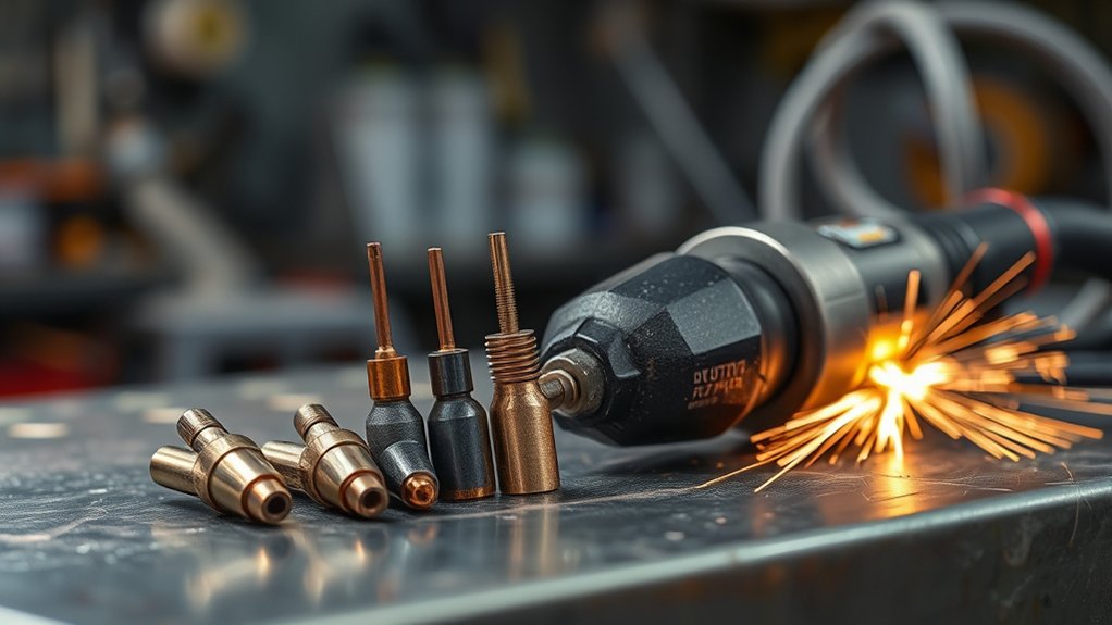
Start with the cut chart for the exact torch and process. Set the correct current, gas type, dynamic pressure, flow, pierce height, cut height, delay, and travel speed. A generic pressure or standoff value cannot replace the model-specific chart.
Supply clean, dry, oil-free gas at the required flow. Drain the compressor, service particulate and coalescing filters, check dryers, and inspect hoses and fittings for leaks or restrictions. ESAB notes that both low and excessive pressure can destabilize the arc, worsen cut quality, and shorten consumable life. Its air-pressure guide also recommends checking pressure while gas is flowing rather than relying only on a static reading.
Keep the torch square to the plate unless the process calls for an angle. Maintain the specified standoff or use the correct drag shield. Miller’s plasma-cutting guidance explains that steady standoff and correct technique support both cut quality and consumable life.
Make edge starts when practical. For mechanized piercing, use the specified pierce height and delay before moving to cut height. Avoid firing the pilot arc into open air, and use grate mode when the machine provides it for expanded metal.
Inspect parts before each shift, after a crash, after a sudden cut-quality change, and before precision work. A daily inspection is more useful than waiting for an assumed number of arc hours.
Pro Tip: When cut quality changes suddenly, install a known-good approved set and make a test cut on clean scrap using the published settings. If the problem remains, investigate air supply, grounding, height control, speed, torch alignment, leads, and the torch body instead of consuming another new set.
Selecting Compatible Parts and Brand Considerations
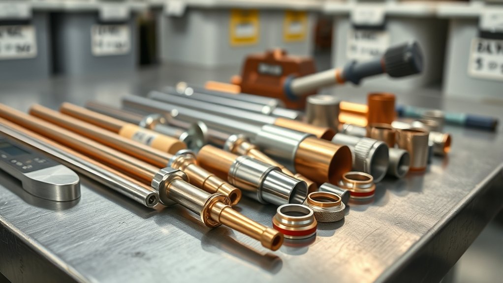
Open the current parts list or operator’s manual and match the exact torch model, process, current, and part number. Do not identify a component by appearance alone. Parts with similar dimensions can have different internal tapers, gas passages, materials, or electrical characteristics.
Before buying, verify:
- Power-source and torch compatibility
- Traditional stack or cartridge platform
- Handheld or mechanized torch
- Shielded, unshielded, drag, fine-cut, marking, or gouging process
- Amperage and gas type
- Required electrode, nozzle, ring, cap, and shield combination
- Current part-number revision or approved replacement number
OEM consumables provide the clearest path to validated fit and published performance. Some aftermarket parts may be usable when the supplier documents exact compatibility, dimensions, materials, quality control, and process limits. A vague claim such as “fits 40–60 amp torches” is not enough.
Do not mix part families unless the torch manufacturer explicitly approves the combination. If an aftermarket part causes poor starts, gas leakage, unusual noise, repeatable bevel, or rapid paired-part damage, stop using it and inspect the torch before installing another set.
Products Worth Considering

PACKAGE INCLUDED: 5 Pcs Cup-15 Pcs Electrodes-10 Pcs Ring-30 Pcs Tip(Standard)

Package Include: 5 Shield Cups, 30 Nozzles, 10 Swirl Baffle, and 15 Electrodes.

Fit for: SG-55 AG-60 plasma cutter torch head.
Troubleshooting Cut Problems Before Blaming Consumables
| Symptom | Possible Causes | First Checks |
|---|---|---|
| Arc will not start | Worn electrode or nozzle, incorrect assembly, loose cap, low pressure, cap-sensor issue, or torch fault | Confirm approved parts and assembly, dynamic gas pressure, cap seating, fault code, and torch condition |
| Pilot arc starts but will not transfer | Poor work-clamp contact, excessive standoff, coated metal, low pressure, or worn consumables | Clamp to clean bare metal near the cut, verify height and pressure, then inspect the nozzle and electrode |
| Wide or wandering kerf | Oval nozzle, excessive cut height, high pressure, low speed, wrong nozzle, or loose torch | Inspect the orifice, verify the cut chart, check torch mounting and perpendicularity |
| Heavy bottom dross | Travel too slow, low pressure or flow, worn parts, wrong current, or material beyond capacity | Check speed, flowing pressure, compressor capacity, nozzle condition, and thickness rating |
| Large bevel on one side | Torch not square, worn nozzle, wrong cut direction, incorrect height, or damaged torch seat | Rotate or replace the nozzle as the manual allows, square the torch, and inspect the electrode seat |
| New nozzle fails quickly | Overused electrode, low pierce height, contaminated gas, mismatched parts, double arcing, or damaged torch body | Inspect the paired electrode, pierce setup, air treatment, part numbers, cap, and electrode seat |
| Sputtering or unstable arc | Moisture or oil, pressure fluctuation, gas leak, poor work connection, blocked swirl ring, or worn parts | Drain and service the air system, test dynamic pressure, inspect hoses, clean the clamp area, and inspect the ring |
Storage, Coolant, and Inventory Practices
Keep new consumables in their labeled packaging or in clean, covered compartments. Separate them by torch, process, and current so similar-looking parts are not mixed. Protect precision faces and openings from metal dust, moisture, oil, impact, and handling damage.
Use clean hands or clean gloves when handling electrodes, nozzles, rings, and cartridges. Do not store loose parts in a pocket or open tray where abrasive dust can enter gas holes or damage sealing surfaces.
For liquid-cooled mechanized torches, use only the coolant specified or expressly approved by the system manufacturer. Coolant chemistry, electrical properties, freeze protection, corrosion inhibitors, filters, seals, and flow requirements vary. Do not assume an automotive antifreeze, welding coolant, deionized water, or generic “low-conductivity” fluid is suitable.
Handheld air-plasma torches commonly rely on air or gas flow rather than a liquid coolant circuit. Do not apply coolant instructions from an industrial liquid-cooled torch to an air-cooled torch.
Maintain a small stock of complete approved combinations rather than large quantities of isolated parts. Rotate older packages first, retain labels and lot information, and record any repeat failure associated with one shipment or supplier.
Frequently Asked Questions
How do ambient humidity and storage affect plasma consumables?
Moisture, shop dust, oil, and handling contamination can affect precision surfaces and gas passages. Keep consumables clean, dry, covered, and labeled in their original packaging or a sealed organizer. Do not rely on a universal humidity or temperature limit unless the manufacturer supplies one for that product.
Can I 3D-print a plasma consumable organizer?
Yes. Use smooth, cleanable material and size each opening so precision faces are not scraped or clamped. Add labels for torch model, process, amperage, and part number. Keep the organizer covered and away from grinding dust, cutting spray, direct heat, and oily tools.
What signs point to torch-body damage instead of normal consumable wear?
Warning signs include a pitted or misaligned electrode seat, cracked torch head, damaged threads, exposed wires, leaking gas or coolant, blocked vents, a faulty trigger or cap sensor, repeated one-sided wear, and new consumables failing immediately. Stop using a damaged torch and follow the manufacturer’s service procedure.
Are aftermarket cooling fluids compatible with plasma torches?
Do not assume they are. Use the coolant listed for the exact liquid-cooled system unless its manufacturer publishes an approved alternative. The wrong fluid can affect electrical resistance, corrosion protection, seals, pump life, cooling performance, and warranty coverage.
How can CNC pierce-height errors look like bad consumables?
Piercing too low can throw molten metal into the shield and nozzle, causing double arcing, blocked holes, and rapid front-end damage. Piercing too high can delay transfer or create unreliable starts. Verify initial height sensing, pierce height, delay, cut height, torch voltage calibration, and the published cut chart before replacing another set.
Should I replace the electrode and nozzle together?
Many manufacturers recommend inspecting them as a pair, and some recommend replacing both together for consistent performance. However, follow the instructions for your torch or cartridge. Never install a new nozzle over an electrode that has exceeded its wear limit, because the worn electrode can quickly damage the new nozzle.
Why do new plasma consumables sometimes fail immediately?
Common causes include mismatched parts, incorrect assembly, a worn paired component, contaminated air, low pierce height, excessive current, overtightening, a damaged electrode seat, or a gas leak. Confirm every part number and process setting before assuming the new component is defective.
How do I know when a single-piece plasma cartridge is worn out?
Use the cartridge-life indicator, end-of-life message, data display, or inspection method supplied for the system. Replace a cartridge sooner if it is cracked, contaminated, incorrectly recognized, or produces poor cuts after air, grounding, height, speed, and setup have been verified.
Conclusion
Each plasma consumable has a precise job, but the correct design and replacement limit depend on the torch. Inspect the electrode, nozzle, swirl ring, retaining cap, shield, seals, and accessible torch surfaces before each shift and whenever cut quality changes. Use measured wear and visible condition instead of a universal hour estimate.
Match every part to the torch, process, current, gas, and cut chart. Keep the air clean and dry, verify pressure while gas is flowing, maintain the specified standoff and pierce height, and avoid unnecessary pilot-arc time. Use only approved coolant and O-ring lubricant where the system requires them. These habits produce steadier edges, fewer misfires, less unexpected downtime, and more useful consumable-cost records.
Sources
- Hypertherm Powermax Preventive Maintenance — traditional consumable inspection, electrode-pit example, swirl-ring inspection, O-ring care, and retaining-cap installation.
- Hypertherm Single-Piece Cartridge Guide — modern cartridge systems, end-of-life tracking, arc-start data, and replacement of the traditional stack.
- ESAB: Understanding How Plasma Cutters Work — consumable functions, arc transfer, cut variables, and model-specific gas settings.
- ESAB Plasma Cutting Air-Pressure Guide — dynamic pressure, airflow, filtration, moisture, cut symptoms, and consumable wear.
- Miller: Plasma Cutting Tips — standoff, paired electrode and tip inspection, pilot-arc use, and finger-tight retaining cups.
- OSHA Welding, Cutting, and Brazing Hazards — electrical, radiation, fume, burn, eye, and other hot-work hazards.