How FineCut Consumables Improve Thin-Metal Plasma Cutting
What’s in This Article
- How FineCut Consumables Improve Edge Quality on Thin Sheet
- Matching Torch Height and Speed for Thin-Metal Precision
- Choosing the Right Power Level and Gas for Fine Features
- Consumable Selection: SYNC Cartridges vs. Traditional Sets
- Monitoring Wear: Signs, Checks, and Replacement Intervals
- Table Motion and Height Control Requirements for Best Results
- Troubleshooting Dross, Bevel, and Edge Ripple on Light Gauge
- Safety and Material Considerations for Thin Stainless and Mild Steel
- Frequently Asked Questions
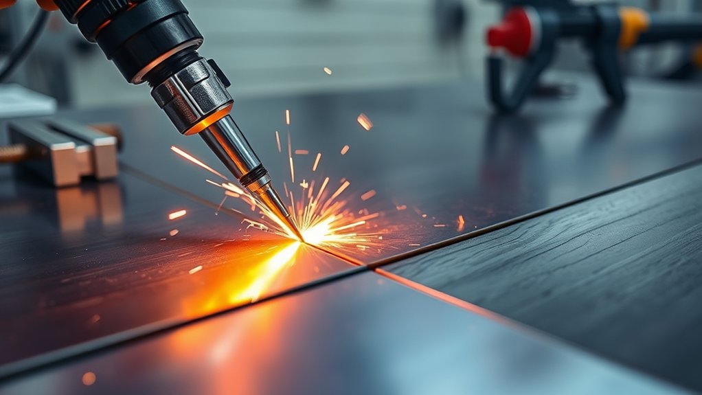
Thin stainless signage can punish small setup errors fast. If you use the wrong torch height, speed, or worn parts, you get dross, bevel, ripple, and extra cleanup. FineCut consumables help you cut thin sheet with a tighter kerf, cleaner edge, and smaller heat-affected zone when you set the process with care.
Quick Answer
FineCut consumables improve thin-metal plasma cutting by shaping a narrow, stable arc at low amperage. You get the best results when you match torch height, travel speed, amperage, gas quality, and consumable condition to the cut chart. For thin stainless and mild steel, small changes in height or speed can quickly affect dross, bevel, and edge finish.
Key Takeaways
- Use FineCut consumables for thin sheet when you need a narrow kerf and cleaner edge.
- Match torch height, cut speed, amperage, and gas quality before you judge cut quality.
- Inspect nozzles and electrodes often because wear can cause arc wander, bevel, and dross.
- Use test coupons before production so you can tune settings without wasting finished parts.
- Control fumes, eye hazards, heat, and electrical risk every time you cut stainless or coated steel.
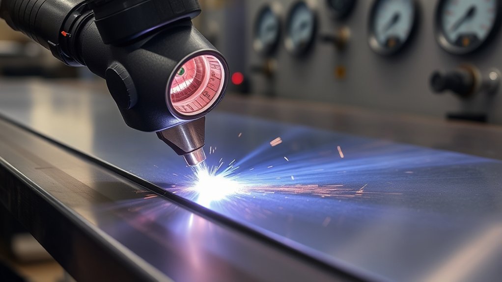
How FineCut Consumables Improve Edge Quality on Thin Sheet
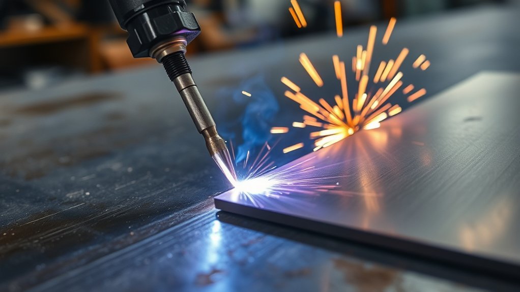
FineCut consumables help you control thin sheet because they stabilize the arc at lower current. They also help you hold a consistent kerf on mild steel and stainless steel when you stay within the rated range.
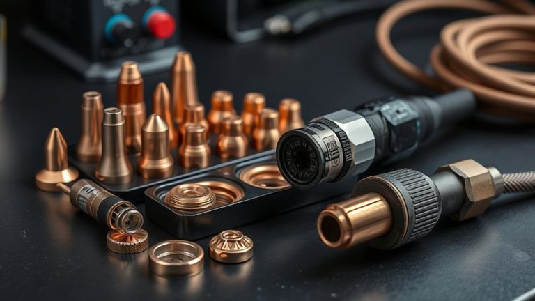
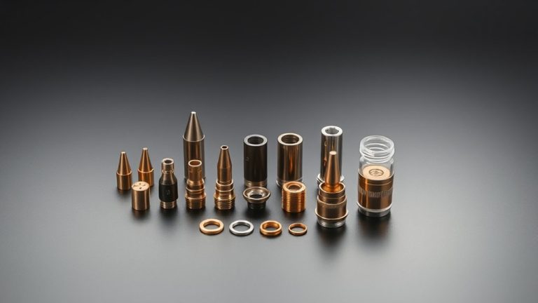
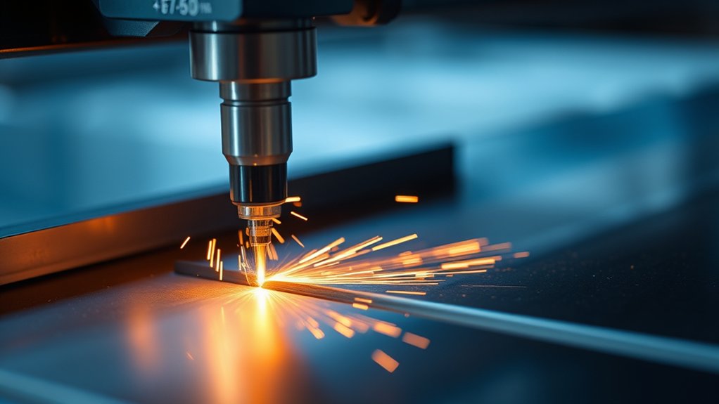
You use conical tip geometry to constrict the plasma column. This boosts arc density and gives the arc better directional control. That precision can mean minimal dross, cleaner edges on 26 gauge sheet, and less heat input.
Lower heat input helps limit warpage, bevel, and a wide heat-affected zone. You may also see a flatter edge profile and less micro-burr formation when the setup stays stable.
Use disciplined cutting habits. Verify the orifice condition, align gas flow, and confirm that amperage matches the sheet thickness.
Maintain a constant arc length to protect edge straightness and surface smoothness during 2-D paths. Watch electrode wear closely. As pit depth grows, arc wander can increase and edge quality can drop.
Swap tips at set intervals to preserve kerf consistency and cut fidelity. With fewer defects, you can reduce secondary grinding and cut total cycle time.
Matching Torch Height and Speed for Thin-Metal Precision
Two variables control most thin-metal precision: torch-to-work height and travel speed.
To hold a constant arc length on sheet thinner than 10 gauge, match torch height to a verified cutting speed from the cut chart. Then lock both settings before you run parts.
Start with the charted stand-off for FineCut consumables. On very thin stock, a speed near 195 inches per minute can serve as a starting point when your machine, material, and cut chart support it. Fine-tune in small steps after a test cut.
Match torch height to verified speed, then lock both. Start near the charted speed, test the edge, and fine-tune one setting at a time.
Watch kerf behavior. Bottom-edge dross can point to slow speed or excess torch height. Beveled edges can point to height that runs too high or speed that runs too fast.
If ripples trail the cut, stabilize motion and restore the programmed feed rate. Adjust one variable at a time. Correct speed first, then trim height by 0.005 to 0.010 inch if you need more arc stability.
Use a height control to maintain steady arc voltage. Probe each pierce so the system can reset zero before the next cut.
Monitor cut speed through the whole toolpath. Adapt torch height to contour changes so you can protect the edge finish.
Choosing the Right Power Level and Gas for Fine Features
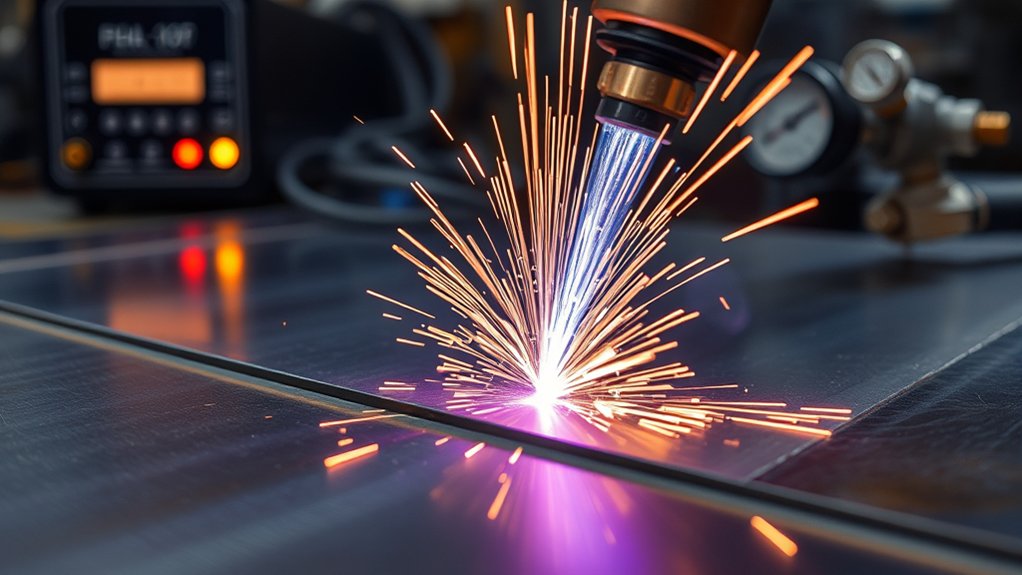
When fine features drive the tolerance stack, set output current low and stable. FineCut work often runs in the 30 to 45 amp range, based on the torch, material, thickness, and cut chart.
A stable low-current setup can tighten kerf width and reduce heat input. You can get sharper radii, cleaner pierces, and less recast when motion and height also stay controlled.
Use careful power optimization. Verify that actual arc amperage matches the setpoint, then lock it in to avoid micro-taper.
For gas selection, run dry, oil-free shop air if your system and cut chart call for air. Clean air supports steady edge quality and keeps the setup simple on thin stock.
Pair that with a consistent 0.06 inch standoff only when your chart supports that setting. A stable standoff helps steady the arc column and reduce bevel and dross.
Maintain a traverse speed near 195 inches per minute only as a test starting point for very thin paths when it matches your system data. Adjust about 10% at a time based on edge color, lag lines, and spatter.
Audit consumable condition often. A rounded electrode pit or widened nozzle orifice can hurt feature definition and increase dross.
Swap components at the first sign of arc wander. Validate cut quality with coupon tests before you release programs to production.
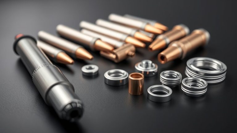
Consumable Selection: SYNC Cartridges vs. Traditional Sets
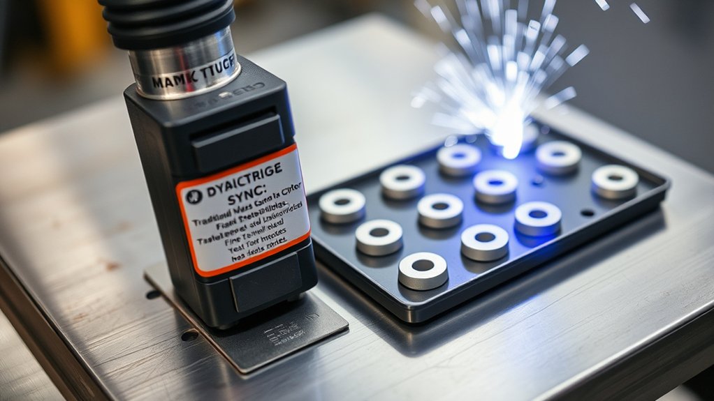
Amperage, gas, and standoff only help when the wear stack holds tolerance. Your next choice is consumable architecture: SYNC cartridges or traditional multi-piece sets.
If you chase FineCut edge fidelity on sheet up to 10 gauge, SYNC cartridges can reduce setup variation. The single-piece cartridge design keeps the nozzle, electrode, and shield aligned as one unit. That helps stabilize arc geometry and reduce kerf wander.
Some Powermax45 SYNC setups may deliver longer consumable life than traditional parts when you use the correct cartridge and settings. Longer life can support faster setup, cleaner thin-stock edges, and more predictable work.
SYNC cartridges reduce part-matching errors, while traditional sets give you more individual parts to inspect and manage.
Traditional sets still work well when you inspect and assemble them with care. Their limits show up when you mix parts, miss wear, or tear down the torch often. Multi-piece sets need inspection discipline and consistent assembly.
SYNC cartridges use built-in intelligence on compatible systems to help load correct parameters. That can save setup time because the machine can identify the cartridge and apply matching settings.
The goal stays the same with either style. You want tighter bevel control, lower dross, stable kerf width, and predictable per-part cost on thin-metal work.
Monitoring Wear: Signs, Checks, and Replacement Intervals
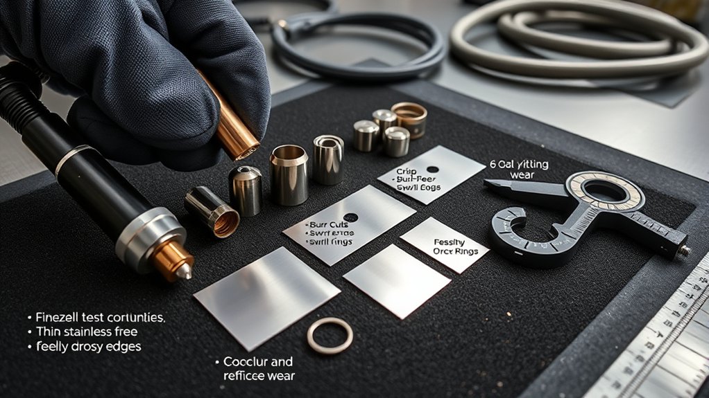
SYNC cartridges simplify setup, but you still need disciplined wear monitoring to keep cut geometry in spec. Treat consumables as critical path parts. Verify condition, track life, and replace parts before they damage cut quality.
Use objective wear signs instead of guesswork. This helps you control replacement timing and avoid rejected parts.
- Inspect the nozzle and electrode. After each nest or heat, check them under magnification. Look for orifice ovality, edge pitting, and tip erosion. Pull the set if you see clear asymmetry because it can cause bevel and kerf growth.
- Log the electrical signature. Track arc voltage during stable cuts. Rising or erratic voltage can point to internal erosion. Link voltage drift to cut quality and set a firm changeout limit.
- Use count-based intervals. Start with a shop baseline, then adjust it for material, thickness, pierce count, and duty cycle. Record pierce counts so you do not overrun worn parts.
- Protect the nozzle during piercing. Use the correct standoff, preflow timing, and pierce method. Poor piercing can damage the nozzle orifice, shorten life, and skew cut geometry.
Table Motion and Height Control Requirements for Best Results
Tight consumable control only pays off when the torch rides at the right height. The table must also move with repeatable motion. You lock in thin-gauge cut quality when torch height and table motion stay tuned and verified.
Set the torch-to-work distance from the Powermax cut charts for FineCut or from the chart for your specific plasma system. Correct standoff preserves arc focus, reduces bevel, and helps control dross.
Use a responsive torch height control that reads arc voltage accurately and filters noise. This helps keep surface waviness from turning into height error.
Validate table motion with periodic performance checks. Confirm commanded speed against actual velocity, acceleration, and corner behavior. Recalibrate when the machine drifts outside your shop tolerance.
Use smooth cornering profiles to maintain steady motion through direction changes. Avoid hard deceleration and acceleration because they can distort kerf and push molten material to the edge.
Document feed-rate windows for each thickness. Then audit cuts to verify kerf symmetry. When height control and motion stay stable, you can produce flat, uniform edges more often.
Troubleshooting Dross, Bevel, and Edge Ripple on Light Gauge
When light-gauge cuts show dross, bevel, or edge ripple, start with the easiest checks. Verify torch-to-work height, confirm the torch height control (THC) reads arc voltage cleanly, and make sure the shield and sensing setup match your torch.
Height errors drive dross formation and skew kerf. Validate pierce and cut heights, then run a short test cut to confirm stability.
- Set amperage within FineCut limits and match it to thickness. Too much current widens the kerf. Too little current can starve the arc and hurt bevel control.
- Lock in feed rate from the cut chart and avoid velocity ripple in corners. Low speed can leave dross. Excess speed can stretch the arc and cause bevel.
- Inspect consumables for nozzle orifice growth and electrode wear. Replace parts when you see double-arcing, taper, or clear arc wander.
- Verify consumable stack-up and shield match. Use FineCut nozzles with the correct shield for your torch. Confirm concentricity, gas flow, and THC response to hold steady stand-off.
Pro tip: Change only one setting per test cut so you can see which adjustment fixed the edge.
Safety and Material Considerations for Thin Stainless and Mild Steel
Before you strike an arc on thin stainless or mild steel, set safe process controls. You need to protect operators and preserve cut quality at the same time.
Use safety measures every time you cut. Wear verified personal protective equipment (PPE), ground the work surface, use a dry air supply, and run fume extraction. Treat galvanized steel as a separate material because heated zinc fumes can be dangerous.
Warning: Do not cut galvanized or coated steel without proper local exhaust, respiratory protection, and shop approval.
Dial in the torch-to-work distance. Correct standoff keeps the kerf narrow, edges flatter, and dross lower. Run FineCut consumables within spec, then match amperage, travel speed, and gas flow to sheet thickness and alloy.
Chemical composition can vary across material types. Higher alloy content or coatings can shift arc behavior, so fine-tune height control, pierce delay, and cut speed.
Audit consumable wear often. Inspect electrodes and nozzles at set intervals. Replace parts before pit depth or orifice erosion hurts geometry.
Document parameters by material and heat lot when repeatability matters. Lock out setting changes until quality control reviews them.
Frequently Asked Questions
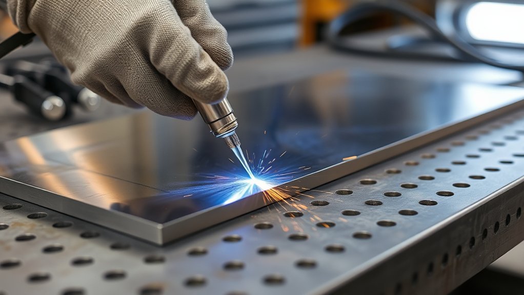
Do Fine Cut Consumables Work With Hand Torches or Only CNC Tables?
Fine Cut consumables can work with hand torches and computer numerical control (CNC) tables when the torch and plasma system support them. On hand torches, they help with precise low-amp trimming. On CNC tables, they help you hold tighter kerf, steadier standoff, and cleaner repeat cuts.
What Minimum Thickness Benefits Most From Fine Cut Tips?
Thin sheet in the 22 to 16 gauge range often benefits most from Fine Cut tips. You still need to match amperage, standoff, speed, and gas quality to the cut chart. Good setup helps you avoid warpage, dross, and tapered edges.
Are Fine Cut Parts Compatible With Water Tables and Downdraft Systems?
Fine Cut parts can work with water tables and downdraft systems when your plasma table and torch setup support them. For water tables, keep splash under control and protect the air supply. For downdraft systems, manage capture velocity and place fume control close to the torch path.
How Do Fine Cut Consumables Affect Kerf Width and Part Nesting Efficiency?
Fine Cut consumables can narrow kerf width when you set the arc and motion correctly. A narrower kerf may help you place parts closer together in a nest. Always confirm spacing with test cuts because heat, pierce spacing, and part geometry still affect yield.
Can Fine Cut Settings Be Stored as Cut Charts in CAM Software?
Yes. You can store Fine Cut settings as cut charts in computer-aided manufacturing (CAM) software. Save amperage, arc voltage, kerf, pierce delay, feed rate, and height control values so repeat jobs start from the same baseline.
Safety Disclaimer: This article is for informational purposes only and does not replace hands-on training, shop safety rules, or professional guidance. Always follow your plasma cutter manual, local safety rules, and qualified supervisor instructions before cutting metal.
Conclusion
You get the best FineCut results when you treat height, speed, amperage, gas, motion, and consumable wear as one system.
Start with the cut chart, run a test coupon, and adjust one variable at a time. Choose SYNC cartridges or traditional sets based on your workflow, then track wear before it damages part quality.
Keep safety controls in place, especially when you cut stainless, galvanized, or coated steel. With a stable setup, you can produce crisp edges, reduce cleanup, and hold repeatable results on thin metal.