You’ll get cleaner cuts, longer consumable life, and safer operation when you match plasma nozzle size to material and amps, watch for wear, and follow standards-based upkeep. Small orifices suit fine detail; larger ones handle thick plate. Misalignment, out-of-round orifices, and excess dross signal replacement. Routine inspections, correct gas flow, and documented hours help prevent blowouts and taper. Curious which sizes map to your amperage, and when to swap before quality drops?
Key Takeaways and Market Trends
Although the plasma cutting machine market is expanding—surpassing $770.6 million in 2023 and projected to grow at 5.7% CAGR through 2032—the key takeaways center on efficiency, nozzle selection, and maintenance discipline.
You’ll feel the effects of market growth through tighter specs, faster turnaround expectations, and rising demand for consumables. Align your process with nozzle innovation that enhances arc stability and protects critical components, especially under higher duty cycles.
Select nozzles by amperage, gas, and material thickness to maintain kerf accuracy, edge quality, and cut speed. Mismatch leads to double-arcing, bevel, and excess dross, undermining throughput.
Dual flow designs are gaining traction for extended life and better shield gas protection, improving cost per cut in heavy industries such as shipbuilding.
Adopt maintenance best practices: inspect orifice wear, check concentricity, monitor gas quality, and replace at defined wear limits.
Document settings, consumable lot codes, and cut metrics to standardize results and sustain operational efficiency.
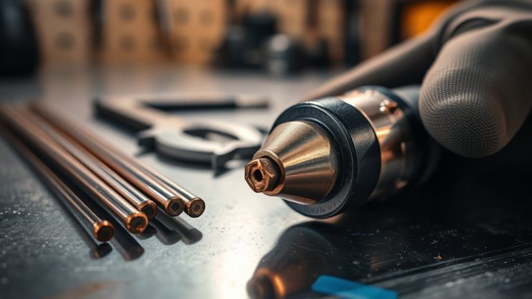
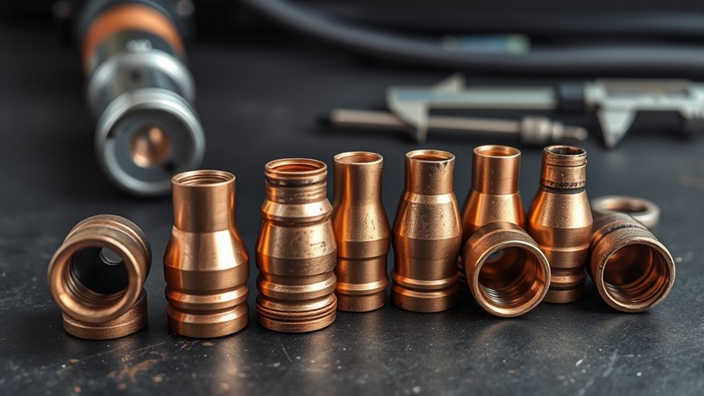
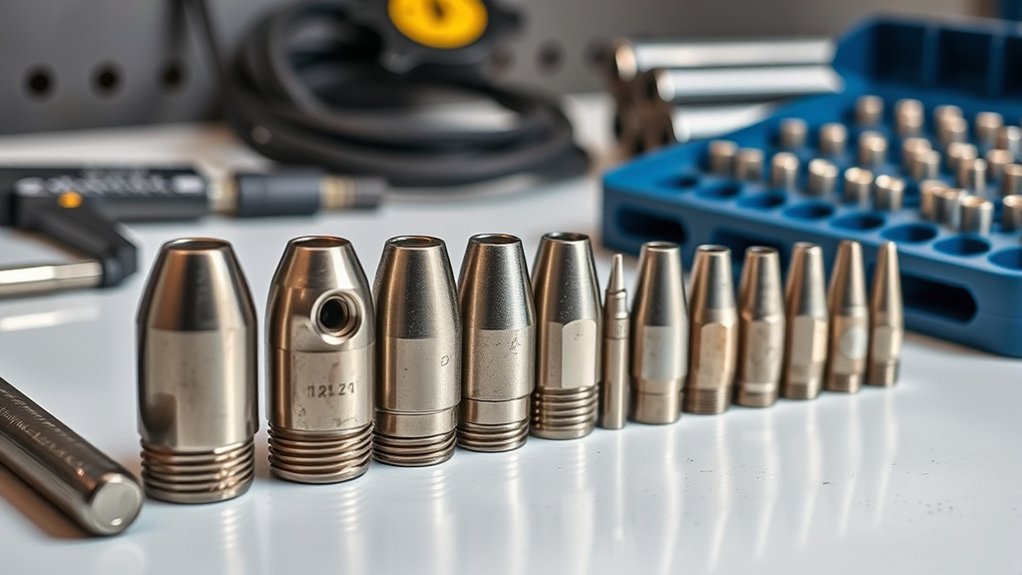
Types of Plasma Cutter Nozzles
As tighter specs and higher duty cycles push you toward better nozzle discipline, understanding nozzle types lets you match arc characteristics to the job.
Standard nozzles are the baseline for most materials and thicknesses, balancing cut quality, speed, and consumable life.
Shielded nozzles add a secondary shield to isolate the arc from spatter and workpiece contact, improving precision, edge finish, and operator safety in mechanized or high‑accuracy nozzle applications.
Drag tip nozzles let you place the torch directly on the work surface, stabilizing standoff for hand cutting, templates, and tight contours. They’re ideal when portability and repeatable tracing matter more than maximum speed.
Swirl nozzles shape the gas stream to focus the arc, boosting cut speed, kerf straightness, and dross control on thin to medium plate.
Match orifice to amperage for consistent results; for example, a 20 A nozzle typically uses a 0.6 mm orifice, tightening the jet for finer kerfs.
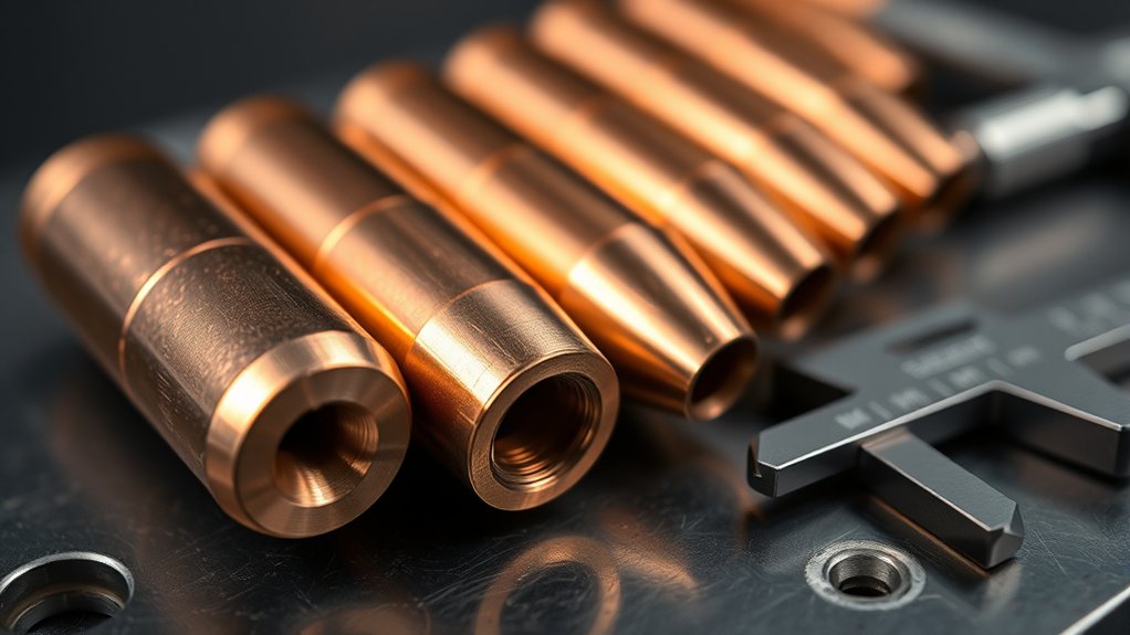
How Plasma Nozzles Work
You control cut quality by using the nozzle to constrict plasma gas, forming a focused arc that exceeds 30,000°F for stable energy density.
Match orifice size to amperage—e.g., a 20 A tip with a ~0.6 mm hole—to maintain proper jet velocity and temperature per manufacturer specs.
This alignment of gas constriction physics and orifice-amperage pairing sets your baseline for speed, kerf, and repeatable results.
Gas Constriction Physics
While the torch generates the plasma, the nozzle’s job is to constrict the gas stream so the arc accelerates, heats, and stays coherent through the cut. You exploit plasma dynamics: as the gas funnels through the nozzle throat, pressure drops, velocity rises, and Joule heating spikes arc temperature beyond 30,000°F. This constriction improves nozzle efficiency by stabilizing the column, minimizing divergence, and tightening the kerf.
- Constriction shapes momentum transfer, so molten metal ejects cleanly; improper geometry increases dross and taper.
- Shielded and drag tip designs manage standoff and spatter, protecting the orifice and preserving laminar flow near the exit.
- Thermal loading is extreme; copper alloys, hafnium inserts, and cooling paths are selected to limit erosion and maintain arc attachment stability.
Match geometry to speed and precision requirements.
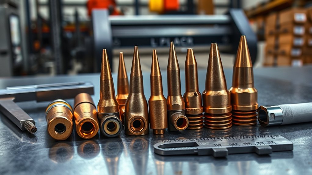
Orifice Size and Amperage
Constriction shapes the arc; orifice size sets how much current and gas the nozzle can handle without losing coherence. Match orifice diameter to amperage: a small opening (e.g., 0.6 mm for a 20 A tip) focuses the arc for fine features and thin stock.
As amperage rises, you need a larger orifice to pass higher gas flow, maintain arc stability, and cut thicker materials without blowout or double-arcing.
Correct sizing preserves velocity and temperature, driving cutting efficiency, speed, and edge quality. Plasma stream temperatures can exceed 30,000°F (16,649°C); an undersized orifice at high current overheats, while an oversized one diffuses the jet and slows cutting.
Inspect for wear—enlarged orifices degrade accuracy and kerf. Replace nozzles to maintain rated current, productivity, and compliance with manufacturer specs.
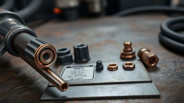
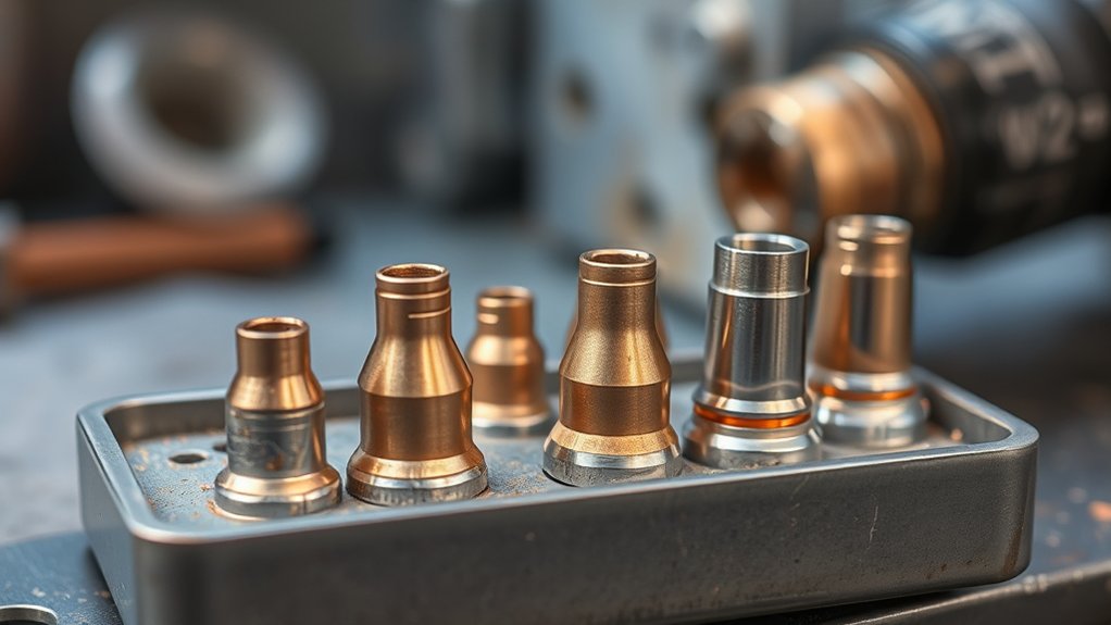
Selecting the Right Nozzle Size and Type
Choosing the right plasma cutter nozzle starts with matching orifice size and type to your material, thickness, and amperage.
Prioritize nozzle compatibility with your torch and consumables kit to maintain cutting efficiency and meet manufacturer specifications. Smaller orifices concentrate the jet for fine detail; larger orifices support higher amperage for thicker sections. For reference, a 20 A nozzle typically uses a 0.6 mm orifice for its rated thickness range.
Select standard nozzles for mild steel; use fine-cut or shielded variants to improve edge quality on thin materials. Align the nozzle’s amperage rating with your set current to avoid instability and premature wear.
- Verify material and thickness, then choose orifice size that balances kerf width, speed, and tolerance.
- Match nozzle type (standard, fine-cut, shielded) to application: precision vs productivity.
- Consider geometry: longer nozzles aid high-speed cuts; shorter nozzles improve control on detail work.
Confirm gas, standoff, and torch model per OEM charts before cutting.
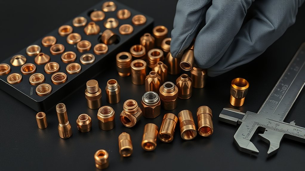
Common Wear Signs and Troubleshooting
After sizing and type are set, maintaining cut quality depends on spotting nozzle wear before it degrades performance.
Prioritize repeatable checks that protect nozzle lifespan and enable wear prevention. Don’t rely on a quick glance—clouding can hide defects. Inspect the orifice for roundness; an irregular or oblong shape means the jet isn’t focused, so kerf widens and cut quality drops.
Verify the entrance edge: a new, sharp edge will round with use, reducing precision and increasing dross.
Track orifice growth and exterior dishing. An enlarged orifice and visible dish are clear wear indicators correlated with jagged edges and inconsistent arc stability. If you see these, reduce current to match tip rating or replace the nozzle to restore performance.
Troubleshoot cut issues systematically: excessive dross, bevel, or arc wandering often trace to nozzle wear. Confirm consumable compatibility, pierce count, and cut length against spec to decide whether to continue, adjust parameters, or replace.
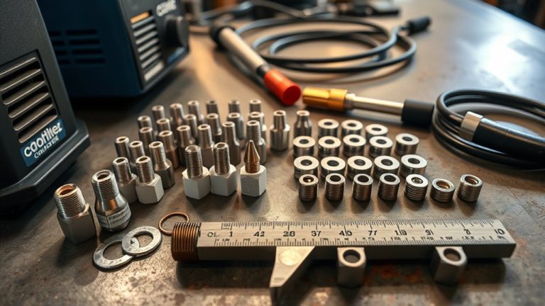
Maintenance, Cleaning, and Installation Tips
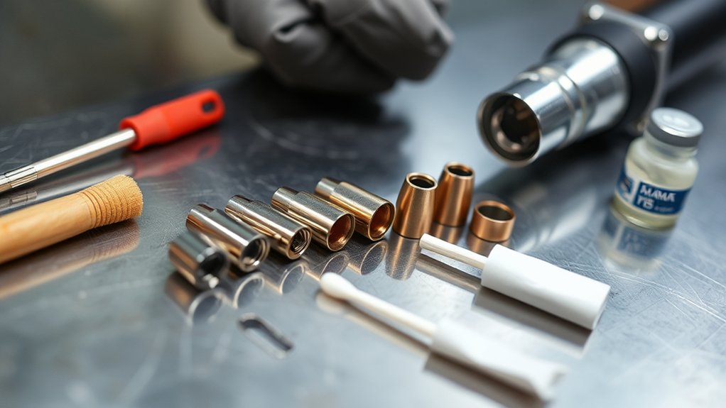
Start by letting the nozzle cool fully after cutting, then handle it with PPE and clean with compressed air and a lint‑free cloth—no harsh chemicals.
During installation, seat the nozzle straight, confirm proper standoff, and apply snug torque without overtightening to protect threads and maintain alignment.
Inspect for wear (orifice growth, cracks, discoloration) and replace about every 40 pierce starts to sustain cut quality and system integrity.
Cooling and Safe Handling
Even when a cut looks finished, treat the nozzle like a hot workpiece: let it cool fully before you touch or remove it to prevent burns and thermal shock.
Apply cooling techniques that don’t quench the metal abruptly—idle airflow or natural convection is safer than dunking. Prioritize safe handling: de-energize the torch, wear heat-rated gloves, and keep your grip away from the orifice.
After the nozzle reaches ambient temperature, blow out debris with clean, dry compressed air and wipe it using a lint-free cloth. For stuck-on slag, use a soft wire brush. Avoid harsh chemicals or abrasives that enlarge the orifice.
- Inspect for oblong or irregular orifices; replace if deformed.
- Verify the nozzle seats fully and sits straight; check o-rings for wear.
- Maintain cleanliness to stabilize cut quality and gas flow.
Proper Alignment and Torque
While assembling the torch, seat the nozzle fully and square it before applying torque. Use manufacturer torque specifications to prevent overtightening and thread damage; don’t “snug by feel.”
Apply torque with a calibrated wrench, holding the body to avoid side load. Verify o-ring condition and replace worn seals to maintain gas integrity before tightening.
Use consistent alignment techniques: sight the torch from the front and side to keep it perpendicular to the workpiece, minimizing bevel and distortion.
After changing consumables, clean the torch head and nozzle to guarantee solid electrical contact. Remove slag or debris with a soft wire brush; avoid harsh chemicals that can pit or erode surfaces.
Recheck alignment after tightening, then perform a brief test cut to confirm cut quality.
Replacement Guidelines and Best Practices
Although nozzle life varies by material and duty cycle, you should follow defined replacement thresholds and documentation to keep cuts in spec. Establish a replacement frequency by tracking pierce counts and pit depth across nozzle materials. Replace standard copper electrodes at 0.040 in pit depth; replace silver/hafnium-interface electrodes at 0.080 in.
Track pierce counts and pit depth; replace copper at 0.040 in, silver/hafnium at 0.080 in.
Visually inspect nozzles for enlarged orifices, discoloration, or irregular profiles; swap nozzles about every 40 pierce starts to preserve kerf quality and arc stability. Keep spares staged to avoid downtime.
- Verify the nozzle is fully seated and aligned with the electrode each install; misalignment accelerates orifice growth and taper.
- Record part numbers, pit measurements, pierce counts, and cut results; use the log to refine intervals and control consumable cost per part.
- Standardize torque, seating checks, and inspection criteria in a work instruction; train operators to reject borderline components.
Document conditions, trend wear versus amperage, material, and duty cycle, and adjust schedules to maintain consistent tolerances.
Frequently Asked Questions
How Do Ambient Temperature and Humidity Affect Nozzle Performance?
Ambient temperature and humidity alter arc stability, cooling, and oxidation, directly impacting nozzle performance. You mitigate wear by enforcing temperature control, managing dew point, drying air supply, and tightening nozzle maintenance intervals per manufacturer specs, ISO 9013 quality targets, and duty-cycle limits.
Can Nozzle Design Impact CNC Cut Path Accuracy?
Yes—nozzle design drives CNC path accuracy. You’ll see up to 20% variance in kerf deviation from nozzle geometry alone. Choose concentric orifices, proper standoff, and matched gas flow to improve cut quality, minimize taper, and stabilize arc alignment.
Are There Eco-Friendly Disposal Methods for Used Nozzles?
Yes. You can pursue recycling options through metal scrap programs, manufacturer take-back, or certified e-waste facilities. Verify alloy composition, segregate consumables, and document chain-of-custody. Follow local disposal regulations, hazardous waste classifications, and ISO 14001-aligned environmental management practices.
What Training Reduces Operator-Induced Nozzle Damage?
You’ll prevent more damage than you think with operator training focused on standoff control, pierce sequencing, amperage/nozzle matching, gas flow checks, and consumable inspection. Standardize procedures, log parameters, practice torch-height calibration, and enforce nozzle cooling intervals for rigorous damage prevention.
How Do Different Gases Influence Nozzle Longevity and Kerf Quality?
Different gases change nozzle longevity and kerf quality via gas composition and temperature. You’ll get longest life using nitrogen or air with compatible nozzle materials; argon-hydrogen cuts fastest but erodes nozzles. Follow manufacturer standards for pressure, flow, and cooling.
Conclusion
You’ll get consistent, standards-compliant cuts when you match nozzle size to material, inspect wear, and replace on schedule. Choose the correct orifice for thickness, keep components clean, and document hours to meet OEM thresholds. Watch for oval orifices, bevel, and excess dross; troubleshoot alignment and gas settings first. Train operators and calibrate consumables like a gauge block—precise and repeatable. When in doubt, replace early to protect cut quality, extend torch life, and sustain productivity.