

Welding a body-on-frame vehicle means working on the separate chassis that supports the body, drivetrain, suspension, steering, hitch, and other major loads. A safe repair starts with the exact VIN and model-year procedure—not a generic weld setting. Before any cutting or welding, the frame material, permitted repair area, alignment points, electronics, fuel system, and corrosion protection must all be identified.
Quick Answer
Body-on-frame welding can repair a separate truck or SUV chassis, but only when the vehicle maker permits the repair and the technician follows the exact model-year procedure. The work requires material identification, frame measurement, controlled welding, component protection, post-weld inspection, and restored corrosion protection.
Key Takeaways
- Confirm the VIN, model year, wheelbase, powertrain, frame material, and current manufacturer repair procedure before touching the frame.
- Do not assume MIG, TIG, preheat, a fish plate, or a particular filler is acceptable. The approved process and joint design vary by vehicle.
- Measure frame rails, crossmembers, suspension mounts, steering points, hitch mounts, and body mounts before and after structural work.
- Isolate electrical, fuel, brake, hydraulic, restraint, and high-voltage hazards according to the vehicle maker’s instructions.
- A finished repair needs weld inspection, geometry verification, corrosion protection, system scans, fastener checks, and documented return-to-service approval.
At a Glance
| Time Required | No universal time applies. Measurement and planning may take hours, while straightening, section replacement, coating cure time, alignment, and inspections can keep the vehicle in a qualified shop for several days. |
| Difficulty | Expert structural repair. Major rails, suspension mounts, steering mounts, hitch points, crash-related areas, and electrified vehicles require trained technicians and professional equipment. |
| Tools Needed | OEM repair information, frame rack or level support system, tram or electronic measuring system, approved welding equipment and consumables, ventilation, temperature controls when specified, fire protection, scan tool, PPE, and inspection equipment |
| Cost | A reliable price requires an in-person inspection. Cost changes with access, corrosion, measurement time, straightening, replacement sections, electronics, coatings, alignment, and required inspections. |
How Body-on-Frame Welding Works
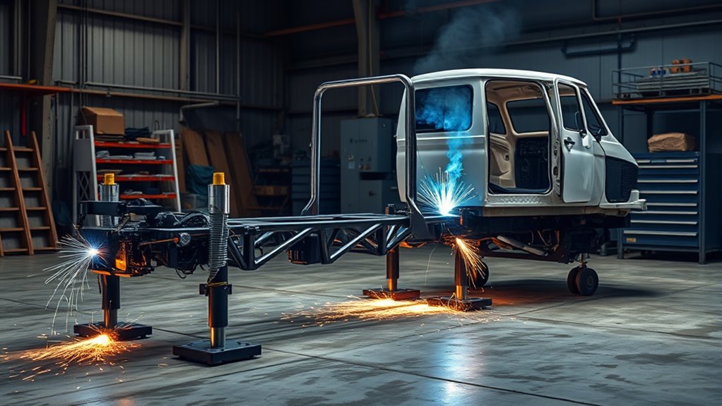
A body-on-frame vehicle uses a separate chassis, often shaped like a ladder, under the cab or body. Frame rails and crossmembers carry loads from the suspension, engine or drive unit, body mounts, cargo, trailer hitch, recovery points, and road impacts.
The first welding decision is not which process to use. It is whether the manufacturer permits welding at that location on that exact vehicle.
Factory assembly may use robotic arc welds, spot welds, structural fasteners, rivets, adhesives, bolts, and formed or hydroformed parts. A repair does not automatically copy the visible factory joint. The repair manual may prescribe a different service joint, replacement section, reinforcement, fastener pattern, or no-weld zone.
Gas metal arc welding, commonly called MIG or GMAW, is used in many steel fabrication and repair operations. Gas tungsten arc welding, commonly called TIG or GTAW, and shielded metal arc welding may also appear in manufacturer or body-builder information. However, process selection must be based on the frame material, joint, access, approved filler, heat limits, and manufacturer instructions—not on which machine is available.
Production stations can align and join repeatable parts under controlled conditions. Field repairs are different because the technician must account for collision deformation, corrosion, fatigue, prior repairs, attached systems, and loss of protective coatings.
Some body-on-frame damage can be isolated to a crossmember, bracket, or replaceable section. Other damage affects a full rail, several mounting points, or the frame’s overall geometry. A localized appearance does not prove that the load path is undamaged.
Effective ventilation and fume control are required during preparation, cutting, and welding. OSHA notes that welding fumes can contain hazardous metals and gases and that outdoor work alone does not guarantee adequate ventilation. See the OSHA welding-fume fact sheet for exposure-control guidance.
Warning: Vehicle frame welding is structural work. Damage involving a major rail, suspension or steering mount, hitch or recovery point, body mount, airbag-related structure, high-voltage component, or severe corrosion should be evaluated by a qualified frame-repair professional with current manufacturer information and measuring equipment.
Body-on-Frame vs. Unibody Welding
Body-on-frame construction separates the body from the main chassis. Bolts, mounts, brackets, rivets, welds, and crossmembers connect the systems. This arrangement can make some brackets, crossmembers, and rail areas easier to access than comparable parts inside an integrated body shell.
A unibody vehicle uses the floor, pillars, rockers, rails, aprons, roof, and other stamped parts as one load-bearing structure. Repairs often involve panel sectioning, squeeze-type resistance spot welding, MIG brazing, adhesives, rivets, or other procedures selected for the specific material and crash structure.
Neither construction type is automatically safer, stronger, cheaper to repair, or better at towing. Those results depend on the complete vehicle design, material grades, suspension, wheelbase, powertrain, hitch rating, crash engineering, and the exact damage.
The main repair difference is the load path. Body-on-frame work focuses on the separate chassis and its mounting points. Unibody work focuses on the integrated shell. Learning proper automotive welding processes is useful, but the vehicle maker’s current repair procedure remains the final authority for both designs.
- A separate frame may allow a damaged crossmember or approved rail section to be serviced without replacing surrounding body panels.
- An integrated unibody repair may involve several overlapping panels and factory joining methods.
- Both designs require accurate measurement, correct materials, restored corrosion protection, and verification of safety-system mounting points.
Verify the Vehicle Before Frame Repair
Before estimating or planning a repair, record the full 17-character VIN and confirm the model year, make, model, cab or body style, wheelbase, drive configuration, engine or electrified powertrain, gross vehicle weight rating, and installed towing or upfitter equipment.
The free NHTSA VIN decoder can help identify information encoded in the VIN. The NHTSA recall lookup should also be checked because an open frame, suspension, hitch, battery, or corrosion recall could change the repair path.
Next, obtain the current manufacturer service manual, collision repair manual, body-builder manual, or technical bulletin for that exact configuration. Current GM body-builder manuals, for example, are organized by vehicle class and model year because dimensions, materials, approved alterations, and electrical precautions vary.
Pro Tip: Save the VIN report, repair-manual revision, frame dimensions, pre-repair scan, measurements, and photographs in the job file. This creates a record showing which procedure was used and what changed during the repair.
Common Frame Materials and Joint Types
Truck and SUV frames may use mild steel, high-strength low-alloy steel, heat-treated steel, multiple steel grades, cast or forged brackets, and formed or hydroformed sections. Aluminum may be present in the body, closures, brackets, crossmembers, or other parts without the main frame rails being aluminum.
Visual appearance, spark testing, or thickness alone may not identify a rail’s grade or heat treatment. Use manufacturer documentation, part identification, and approved testing methods. A replacement rail or reinforcement must match the specified material, strength, thickness, shape, and attachment method.
Factory joints can include welds, bolts, rivets, Huck-type fasteners, adhesives, and combinations of these methods. Do not replace a factory fastener with a weld simply because welding appears stronger. The original joint may be designed to control flexibility, fatigue, serviceability, galvanic corrosion, or crash behavior.
Surface preparation still matters. Clean, dedicated abrasives and dedicated preparation tools reduce contamination. Tools used on carbon steel should not be carried onto aluminum or stainless parts when cross-contamination could cause corrosion or weld defects.
Common Frame Metals
The exact rail material determines whether a part may be straightened cold, heated within a limit, welded, sectioned, reinforced, or replaced. Common categories include:
- Mild or conventional steel: Often more tolerant of forming and welding than higher-strength grades, but still subject to manufacturer limits.
- High-strength low-alloy steel: Offers greater strength for a given section but can lose local properties when excessive heat changes the heat-affected zone.
- Heat-treated steel: May have strict temperature limits or prohibited repair areas. Some applications do not permit welding.
- Aluminum components: Require material-specific cleaning, filler, shielding, heat control, isolation from steel, and dedicated tools. Do not assume an aluminum body means the frame rails are aluminum.
- Mixed-material assemblies: May require coatings, isolators, adhesives, or approved fasteners to prevent galvanic corrosion.
Material selection affects fatigue life, load capacity, corrosion resistance, and how the frame flexes. Never choose replacement plate by thickness alone.
Welding Joint Types
Manufacturer-approved frame repairs may use a groove weld, lap or section joint, plug weld, replacement crossmember, bolted reinforcement, sleeve, or another engineered connection. The correct design depends on where bending and torsional loads pass through the rail.
Terms such as fish plate, sleeve, and reinforcement plate do not describe a complete repair. Plate length, corner radius, end shape, material, orientation, bolt pattern, weld termination, and distance from a flange or mount all affect fatigue performance.
Some manufacturer procedures prohibit welding a reinforcement directly to the original rail and require high-strength fasteners instead. Other procedures allow specific welds but prohibit welding across a flange, along an inside flange edge, or within a designated no-weld zone.
Do not drill, notch, heat, plate, or weld the top or bottom flange unless the exact procedure permits it. A sharp plate end, weld crater, abrupt stiffness change, or hole outside an approved zone can become a new crack origin.
Pro Tip: Mark approved datum points and take side-to-side, lengthwise, height, and diagonal measurements before disassembly. Photograph brackets, shims, wiring clips, brake-line retainers, and body-mount positions before moving them.
Tools and Equipment for Frame Welding
A structural frame repair usually requires more than a welder and grinder. The equipment must support measurement, alignment, safe hot work, and final verification.
- Information: Current OEM repair instructions, material specifications, frame dimensions, wiring diagrams, shutdown procedures, and torque values.
- Measurement: Frame rack, level stands, tram gauge, plumb bobs, datum targets, electronic measuring system, straightedges, and angle or height tools.
- Welding: The approved welding process, correct consumables, shielding gas, clean leads, suitable ground clamp, joint-preparation tools, and test coupons when required.
- Heat control: Temperature-indicating crayons, contact thermometer, or infrared equipment when the procedure specifies preheat or a maximum interpass temperature.
- Safety: Welding helmet, safety glasses, face shield, gloves, hearing protection, fire-resistant clothing, welding curtains, suitable fire extinguishers, ventilation, and any required respiratory protection.
- Inspection: Bright lighting, mirrors or borescope, magnification, weld gauges, and approved non-destructive test materials or services.
- Vehicle systems: OEM-capable scan tool, battery-support equipment where specified, high-voltage test equipment for trained technicians, and torque tools.
Products Worth Considering

Make sure to measure first, this frame will not fit in all drawers or cabinets, frame dimensions are 15.2"L x 12.4"W x 10.5"H.

Package Content: you will receive a total of 6 PVC hanging file drawer rails in black color, which come in pairs, enough quantity to meet your daily use and replacement demands, allowing you to utilize drawer space more easily; Please check the size before ordering

Suitable for both legal size and letter size,perfect hanging file folder frame for your filing system.
Initial Frame Inspection and Repair Decision
Inspect the whole chassis before deciding that the visible crack or bend is the only problem. Look for:
- Rail sweep, sag, diamond, twist, buckling, bulging, or flange distortion.
- Cracks radiating from holes, brackets, welds, spring hangers, steering boxes, shock mounts, crossmembers, and hitch mounts.
- Loose or missing fasteners and elongated holes.
- Corrosion scale, pitting, perforation, trapped debris, and rust inside boxed sections.
- Damaged body mounts, suspension mounts, brake or fuel-line clips, wiring retainers, and heat shields.
- Prior welds, patches, drilled holes, added equipment, or signs of improper straightening.
- Overloaded springs, mismatched suspension parts, oversized towing equipment, or accessories that may have concentrated stress.
A crack without clear impact damage may point to overload, poor equipment mounting, loose fasteners, corrosion, resonance, or repeated flexing. Repair the cause as well as the crack. Otherwise, stress may return at the weld or move to the edge of a reinforcement.
Replacement is often safer when the rail is deeply corroded, torn through, sharply buckled, stretched, previously repaired several times, damaged in a prohibited zone, or made from material the manufacturer does not allow to be welded.
How to Repair Towing Damage
Towing damage often appears near the hitch, rear crossmember, spring or control-arm mounts, bumper brackets, recovery points, and the rear portions of the frame rails. A bent hitch does not prove that the frame remained straight.
Use the manufacturer’s datum dimensions and a suitable measuring system to check rail spacing, height, diagonal relationship, crossmember position, body mounts, suspension mounts, and the opposite side of the frame.
Inspect the frame for bends, cracks, warping, loose fasteners, and elongated holes because damage in these areas can affect tracking, tire wear, hitch alignment, and towing stability.
- Identify the trailer, tongue-weight, recovery, or impact event that caused the damage when possible.
- Measure the rails and mounting points before removing the hitch or damaged brackets.
- Inspect the hitch, fasteners, rear crossmember, suspension mounts, body mounts, wiring, spare-tire equipment, and fuel system.
- Determine whether the approved repair is straightening, bracket replacement, crossmember replacement, rail section replacement, or another documented method.
- Repeat all measurements after the frame cools and after components are reinstalled and torqued.
Do not increase amperage simply to force penetration into an unknown frame material. The correct amperage range is only one part of the procedure. Joint preparation, polarity, electrode or wire classification, shielding, travel speed, fit-up, position, heat input, and qualification also matter.
After repair, verify wheel alignment, axle or suspension position, hitch mounting, fastener torque, electrical connections, and any driver-assistance sensors affected by ride height or chassis geometry.
Fixing Off-Road Frame Cracks
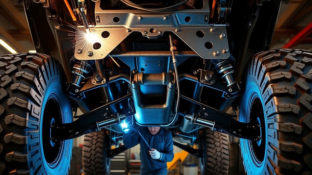
Off-road cracks often develop where repeated torsional flex and shock loads concentrate stress. Common inspection areas include steering-box mounts, spring hangers, control-arm mounts, shock towers, crossmember joints, body mounts, recovery points, and places where aftermarket equipment was attached.
Oversized tires, altered suspension geometry, repeated bottoming, hard recovery pulls, overloading, loose fasteners, corrosion, or a stiff reinforcement beside a flexible rail can all contribute. Identify and correct the cause before closing the crack.
Remove paint, rust, seam sealer, undercoating, wax, oil, and embedded dirt far enough from the work to inspect sound metal and prevent contamination. Welding over rust can produce porosity, lack of fusion, and a repair attached to metal that is already too thin.
Do not automatically stop-drill a crack, gouge it, weld it from both sides, or cover it with a plate. Those operations are appropriate only when the current repair procedure or qualified repair design calls for them. Some cracks require complete removal of the damaged rail section rather than local welding.
The finished frame should retain its intended controlled flexibility rather than becoming merely “rigid.” A reinforcement that is too short, too thick, sharply ended, or attached with the wrong pattern can move peak stress to the edge of the repair.
Note: Reinforcement plates and sleeves must follow an approved drawing. Rounded or tapered transitions may reduce abrupt stiffness changes, but shape alone does not make an improvised repair safe.
Professional Frame Repair Workflow
- Identify the vehicle and procedure. Record the VIN and configuration, check recalls, and obtain the current manufacturer instructions for the exact frame and damage location.
- Inspect and measure. Document corrosion, cracks, deformation, prior repairs, bracket positions, and frame geometry. Determine the cause of non-impact damage.
- Choose repair or replacement. Confirm whether welding, straightening, sectioning, bolted reinforcement, crossmember replacement, or complete rail replacement is permitted.
- Isolate hazards. Follow the specified 12-volt, high-voltage, restraint, fuel, brake, hydraulic, electronic-module, and interior-protection procedures.
- Support and prepare the frame. Place the chassis on a level, stable system, restore required geometry before welding when directed, remove contamination, and fit the approved parts without forcing them into position.
- Complete the approved joining operation. Use the specified process, filler, polarity, joint preparation, weld sequence, heat limits, ground location, fasteners, and technician qualifications.
- Inspect and protect. Complete visual and required non-destructive inspection, remeasure the frame, then restore primer, seam sealer, cavity wax, isolators, and exterior coating.
- Return the vehicle to service. Reassemble with specified fasteners and torque, perform scans and calibrations, verify alignment and hitch or suspension geometry, road-test when safe, and retain repair records.
Welding Prep and Safety Tips
Prepare every weld area to clean, dry metal. Remove rust, scale, grease, moisture, paint, undercoating, seam sealer, cavity wax, zinc-rich coating, and solvent residue that could affect fusion or create hazardous fumes.
Cleaning a coating from the immediate joint does not replace ventilation. Use local exhaust near the fume source when practical, keep the plume out of the breathing zone, and follow workplace exposure and respiratory-protection requirements.
Verify the approved process, voltage, current, wire-feed speed, filler, shielding gas, joint preparation, material thickness, weld position, and heat limits before striking an arc.
Wear a suitable welding helmet, safety glasses, gloves, hearing protection, and fire-resistant clothing. Protect nearby workers with screens and control sparks that can travel into body cavities, carpet, insulation, dry vegetation, or accumulated debris.
Do not preheat a frame because it is thick or because preheat seems likely to reduce distortion. Apply preheat only when the manufacturer procedure or approved welding procedure specifies it. Observe any maximum temperature and interpass limit.
When galvanized or zinc-coated parts are involved, removing zinc from the weld zone helps weld quality, but zinc fumes remain a health concern. Use effective ventilation and any respiratory protection required by the exposure assessment.
- Support and fixture the frame on a stable, level system with the required geometry confirmed.
- Expose clean metal, protect nearby systems, position ventilation, and place suitable fire extinguishers within reach.
- Fit and tack the approved repair while checking dimensions so the joint does not pull the rail out of position.
- Complete the specified weld sequence and allow cooling according to the procedure rather than quenching the repair unless expressly directed.
- Maintain a fire watch and inspect hidden spaces for heat, smoke, smoldering sealer, or damaged wiring after hot work ends.
Electrical, Fuel, Restraint, and High-Voltage Safety
Welding current and heat can damage control modules, wiring, bearings, sensors, fuel systems, batteries, restraint components, and high-voltage equipment. Follow the exact manufacturer shutdown and reconnect sequence.
- 12-volt system: Record required memory information and follow the specified battery disconnect order and waiting period. Some procedures also require connectors to be removed from sensitive modules.
- Welder ground: Attach the return clamp to clean metal as close to the weld as practical and on the same component when directed. Do not allow welding current to pass through bearings, hinges, modules, or wiring grounds.
- Fuel and fluid systems: Locate tanks, lines, vapors, brake hoses, hydraulic lines, refrigerant lines, DEF equipment, and plastic reservoirs. Remove, drain, shield, or reposition them only as the service procedure directs.
- Restraint systems: Airbag modules, impact sensors, pretensioners, and reserve-energy circuits may remain active after a battery is disconnected. Observe the manufacturer’s waiting time and handling instructions.
- Hybrid and EV systems: Treat orange cables, traction batteries, inverters, electric drive units, and high-voltage cooling systems as energized until a trained technician completes the manufacturer’s de-energization and zero-voltage verification procedure.
Warning: Disconnecting a 12-volt battery does not prove that a hybrid or EV high-voltage system is safe. NHTSA advises that traction-battery service be performed by qualified technicians with specialized training and equipment. Do not cut, weld, heat, drill, or clamp near a traction battery or high-voltage cable without the vehicle-specific procedure.
Heat Control and Welding Process Selection
Heat input affects distortion, residual stress, hardness, hydrogen cracking risk, coating damage, and the properties of the heat-affected zone. Higher heat is not automatically stronger, and a large bead is not automatically safer.
The repair procedure may control:
- Permitted welding process and equipment setup.
- Wire, electrode, or filler classification.
- Preheat, maximum temperature, and interpass temperature.
- Bevel angle, root opening, backing, and number of passes.
- Weld length, sequence, direction, and termination.
- Whether reinforcement is welded, bolted, riveted, bonded, or prohibited.
- Whether excess weld is left in place or dressed without reducing the base metal.
- Required test coupons, welder qualification, and inspection method.
Do not use an oxy-fuel torch to straighten or weld a rail unless the vehicle manufacturer expressly permits the operation and supplies temperature controls. Uncontrolled heating can change material properties well outside the visible repair.
Products Worth Considering
✅【Wide Application】: As a versatile plastic water pipe welder, this fusion machine comes with 20mm, 25mm, 32mm,40mm, 50mm, 63mm die heads. It is designed to handle PP, PP-R, PE, PP-C pipes with ease, proving to be the ideal solution for varied sizing requirements in pipe welding tasks.

✅【Wide Application】: As a versatile plastic water pipe welder, this fusion machine comes with 20mm, 25mm, 32mm,40mm, 50mm, 63mm die heads. It is designed to handle PP, PP-R, PE, PP-C pipes with ease, proving to be the ideal solution for varied sizing requirements in pipe welding tasks.

【1600W Hot Air Plastic Welder】 This 1600W plastic hot air welding gun produces a jet of hot air for shaping, bending and welding thermoplastic materials. Professional hot air roofing welder, built-in fan and integrated design, compact and handheld for use, easy-carrying and must-have tool for both beginner and professionals.
Post-Weld Inspection and Corrosion Protection
The repair is not complete when the arc stops. Let the area cool as directed, then clean it enough to inspect the weld and surrounding base metal.
Look for cracks, craters, undercut, overlap, porosity, burn-through, missed edges, incomplete fusion, excessive grinding, arc strikes, flange damage, and distortion. Inspect the back side and the inside of boxed sections where access allows.
Depending on the procedure and risk, inspection may include:
- Visual inspection under bright light and magnification.
- Dimensional and diagonal frame measurements.
- Weld-size or profile measurement.
- Dye-penetrant testing on suitable nonporous materials.
- Magnetic-particle testing on suitable ferromagnetic steel.
- Other non-destructive testing specified by the manufacturer, engineer, fleet, or inspection authority.
Restore every corrosion-protection layer removed during the repair. The system may include epoxy or approved primer, seam sealer, paint, chassis coating, cavity wax, galvanic isolators, drain openings, plugs, and replacement clips. Keep coatings off grounds, threads, brake surfaces, exhaust parts, and other areas where the manufacturer prohibits them.
Pay special attention to the inside of boxed rails and overlapping joints. A weld can look sound outside while moisture enters an unprotected seam and starts corrosion from within.
Alignment and Return-to-Service Checks
Repeat the original frame measurements after welding, after the frame has cooled, and after major components are reinstalled. Compare both sides and verify the relationship between rails, crossmembers, body mounts, suspension points, steering points, hitch mounts, and axles.
Before release:
- Install specified new fasteners and torque them in the required sequence.
- Inspect brake, fuel, hydraulic, refrigerant, coolant, DEF, and electrical systems for damage or leaks.
- Complete pre- and post-repair diagnostic scans and clear only faults that have been properly diagnosed.
- Perform wheel alignment and any required steering-angle, ride-height, camera, radar, or driver-assistance calibration.
- Verify body gaps, mount shims, hitch alignment, spare-tire equipment, exhaust clearance, and suspension travel.
- Road-test only after structural, brake, steering, electrical, and fluid checks pass.
- Document final measurements, weld inspection, coatings, scans, alignment results, and technician approval.
Legal, Inspection, and Insurance Considerations
Frame-repair, inspection, title, disclosure, and insurance requirements vary by jurisdiction, vehicle class, and use. A repair that is technically possible may still require a licensed repair business, engineer approval, state inspection, fleet authorization, or insurer documentation.
For U.S. commercial motor vehicles, 49 CFR §393.201 states that frame welding and welded frame repairs must follow the vehicle manufacturer’s recommendations. It also restricts cutting, notching, bending, and drilling frame flanges except as specified by the manufacturer.
Before modifying wheelbase, suspension mounts, hitch structure, load-carrying equipment, or a commercial chassis, confirm the applicable manufacturer, upfitter, inspection, registration, fleet, and insurance requirements.
Note: This article explains general repair principles. It is not a substitute for the repair manual, an engineered repair drawing, a welding procedure specification, or a vehicle inspection required where the vehicle is registered or operated.
When Not to Weld a Vehicle Frame
Do not proceed with a generic weld repair when:
- The manufacturer prohibits welding in the damaged area.
- The rail material or heat treatment cannot be identified.
- The surrounding metal is deeply pitted, perforated, thin, laminated, or flaking.
- The rail is torn through, sharply buckled, stretched, or separated.
- Damage reaches a steering mount, suspension pickup point, major body mount, hitch point, recovery point, or crash-related structure without an approved procedure.
- The repair would require drilling, cutting, notching, or welding a prohibited flange.
- There are several old patches or signs of repeated cracking.
- The cause of a fatigue crack has not been identified.
- The vehicle cannot be accurately measured and supported.
- The required welding, high-voltage, inspection, or frame-straightening qualifications and equipment are unavailable.
Do not weld over heavy corrosion. A patch attached to weakened metal may hide damage without restoring the original load path. Section replacement, rail replacement, or removal of the vehicle from service may be the safer result.
Frequently Asked Questions
What are the disadvantages of body-on-frame construction?
A separate frame can add mass and may allow more movement between the body and chassis than an integrated shell. Depending on the vehicle, that can affect ride, handling, step-in height, noise, and efficiency. These are design tendencies rather than rules; modern body-on-frame vehicles vary widely.
What is the best welding method for a car or truck frame?
There is no universal best method. The manufacturer’s current repair procedure must specify whether welding is allowed and which process, filler, joint, heat limits, weld sequence, reinforcement, and inspection apply. MIG or GMAW is used in many steel repairs, but that does not make it acceptable for every frame.
Which is stronger: body-on-frame or unibody?
Construction type alone does not decide strength. Body-on-frame designs are often chosen for trucks, towing, upfitting, or off-road use, while unibody designs can provide high stiffness and carefully controlled crash-energy paths. Compare the specific vehicle’s ratings and engineering rather than assuming one construction is always stronger.
Which is more expensive to repair: body-on-frame or unibody?
Either design can be expensive when damage affects major load paths, suspension points, electronics, coatings, or several connected parts. Cost depends more on the damage, access, required measurements, replacement parts, labor, scans, alignment, and manufacturer procedures than on the construction label alone.
Can you weld a cracked truck frame?
Sometimes, but only when the manufacturer permits repair at that location and the surrounding rail is sound. The cause of the crack must be corrected, the frame measured, the approved joint and reinforcement used, and the finished repair inspected and protected. Severe corrosion or damage in a prohibited area may require rail replacement.
Do you need to disconnect the battery before welding on a vehicle frame?
Follow the exact manufacturer procedure. It commonly includes 12-volt battery isolation and may also require module connectors, restraint-system waiting periods, or other precautions. On a hybrid or EV, a 12-volt disconnect does not de-energize the traction system; a trained technician must follow the high-voltage shutdown and verification process.
Is welding a truck frame legal?
Requirements vary by location, vehicle class, and use. U.S. commercial motor vehicle frame repairs must follow manufacturer recommendations under 49 CFR §393.201. Private vehicles may also be subject to state inspection, title, disclosure, insurer, or repair-business rules.
Should every cracked frame receive a fish plate?
No. A fish plate is not a universal repair. Some procedures call for a specific bolted or welded reinforcement, while others require section or rail replacement. Improvised plate thickness, sharp ends, poor bolt placement, or welds across a flange can create new stress concentrations.
Can a heavily rusted truck frame be patched?
A patch is unsafe when the surrounding metal is thin, perforated, layered, or deeply pitted. The repair must connect to verified sound material and follow an approved design. Extensive corrosion may require rail replacement or removal of the vehicle from service.
How do you know whether a frame weld is safe?
A bead’s appearance is not enough. The repair should match the approved procedure, pass visual and any required non-destructive inspection, meet final frame dimensions, retain correct mount and suspension geometry, receive restored corrosion protection, and pass reassembly, scan, alignment, and road-test checks.
Conclusion
Body-on-frame welding can restore a damaged chassis only when the repair follows the exact vehicle procedure. Begin with VIN and material identification, diagnose why the damage occurred, measure the entire load path, and confirm that welding is allowed. Protect electrical, fuel, restraint, and high-voltage systems; control heat and joint design; inspect the finished work; and restore every removed corrosion barrier. Accurate documentation and final geometry checks are as important as the weld itself.
Sources
- General Motors Upfitter Integration Body Builder Manuals — current model-year body-builder, frame, alteration, and electrical information.
- GM Silverado Medium-Duty Chassis Body Builder Manual — frame damage, material, battery, welding, reinforcement, and corrosion examples showing why vehicle-specific procedures are required.
- 49 CFR §393.201 — Frames — U.S. commercial motor vehicle frame condition, welding, flange, and drilling requirements.
- OSHA: Controlling Hazardous Fume and Gases During Welding — welding-fume hazards, coating removal, ventilation, and exposure controls.
- NHTSA VIN Decoder — vehicle identification and model information needed before locating repair procedures.
- NHTSA Electric and Hybrid Vehicle Safety — high-voltage battery hazards and the need for trained EV technicians.




