Set plasma cutter air pressure from the exact manual for your cutter, torch, and process. Do not choose PSI from material thickness alone. First confirm the required airflow in SCFM, then check the pressure at the cutter inlet while air is flowing. The compressor, hoses, couplers, filters, and dryer must all support that demand without a major pressure drop.
Quick Answer
Use the PSI and SCFM listed in your plasma cutter manual, and verify inlet pressure while air is flowing. Published requirements for portable cutters often use about 80–90 PSI at a stated flow, but some machines require a 90–120 PSI or 110–120 PSI incoming supply range.
Key Takeaways
- Treat the plasma cutter manual as the final authority for inlet PSI, airflow, approved gases, filtration, and duty cycle.
- Measure pressure at the cutter inlet after hoses, couplers, filters, and dryers, with air actively flowing.
- Compare the cutter’s required SCFM with the compressor’s delivered SCFM at the same pressure.
- Material thickness usually changes amperage, travel speed, consumables, standoff, and piercing technique—not the incoming air pressure by itself.
- Automatic-pressure cutters may regulate process pressure internally even though they still require a specific incoming supply pressure.
- Dry, oil-free air, unrestricted hoses, clean consumables, and a solid work-clamp connection are essential for stable cuts.
At a Glance
| Time Required | 10–20 minutes for air-system checks and test cuts |
| Difficulty | Beginner to intermediate |
| Tools Needed | Cutter manual, compressor, regulator, inlet-pressure gauge, filters or dryer, scrap metal, clean consumables, and proper PPE |
| Cost | $0 when the existing air system meets specifications; more if you need larger hoses, high-flow fittings, filtration, a dryer, or a higher-output compressor |
Understanding Plasma Cutter Air Pressure and Flow
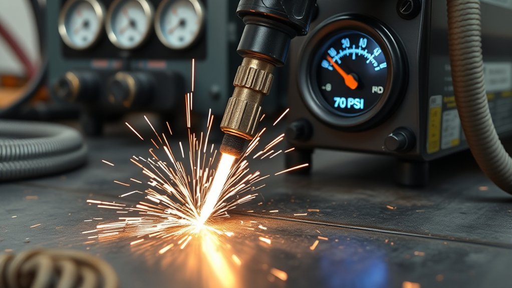
A plasma cutter uses compressed gas to form and control the plasma jet, cool torch components, and eject molten metal from the kerf. Pressure matters, but it is useful only when the air system can maintain the required flow.
Separate the air system into four measurement points:
- Tank pressure: pressure stored inside the compressor tank. It is usually higher than the cutter requires and does not prove that enough air will reach the torch.
- Compressor outlet pressure: pressure set at the compressor regulator before the hose, filters, dryer, and fittings.
- Plasma-cutter inlet pressure: pressure arriving at the cutter after all upstream restrictions. This is the most useful place to check for supply-side pressure loss.
- Internally regulated process pressure: pressure controlled inside the plasma cutter for cutting, gouging, or marking. Some machines set this automatically.
This distinction explains why two pressure numbers may appear in the same manual. A cutter may require a minimum flow at one pressure while also recommending a higher incoming inlet pressure so its internal regulator has enough supply to work correctly.
For example, the current Hypertherm Powermax45 SYNC operator manual lists a minimum cutting-gas requirement of 450 SCFH, equal to 7.5 SCFM, at 85 PSI. It also recommends keeping incoming inlet pressure between 110 and 120 PSI while gas is flowing and prohibits exceeding 135 PSI. The machine then regulates process pressure internally.
Warning: Plasma cutting creates electric-shock, arc-radiation, fume, fire, and burn hazards. Wear the eye shade and flame-resistant PPE specified by the manufacturer. Move combustibles at least 35 feet away or shield them, inspect the hidden side of walls or floors, and provide ventilation at the arc. Never cut a sealed or pressurized container. Do not cut a tank or drum that held hazardous material unless it has been cleaned, tested, vented, and declared safe by a qualified person.
Never substitute oxygen, fuel gas, or another compressed gas because it seems convenient. Use only the gases listed for your exact plasma cutter. Some systems permit clean compressed air or nitrogen, while others support additional process gases under specific conditions.
Typical PSI and SCFM Requirements by Plasma Cutter

There is no universal plasma cutter PSI chart. Manufacturer specifications vary even among machines with similar amperage. Always match the model number and manual revision before connecting the air supply.
| Example plasma cutter | Published air requirement | Important detail |
|---|---|---|
| Hypertherm Powermax30 XP | 4 SCFM at 80 PSI | Requires clean, dry, oil-free air or approved nitrogen |
| Miller Spectrum 375 X-TREME | 5.0 SCFM; 90 PSI minimum and 120 PSI maximum | The requirement is for clean, moisture-free, oil-free gas |
| Hypertherm Powermax45 SYNC | Minimum cutting flow: 450 SCFH, or 7.5 SCFM, at 85 PSI | Recommended incoming pressure is 110–120 PSI while flowing; maximum is 135 PSI |
| Cutter with a built-in compressor | No separate shop-air connection when used as designed | Follow the built-in compressor’s maintenance, duty-cycle, and environmental limits |
These examples show why amperage alone cannot determine the correct pressure. Two 30- or 40-amp cutters may use different internal regulators, torches, nozzles, flow rates, and inlet-pressure ranges.
What Material Thickness Changes
Thicker metal usually requires a different combination of:
- Output amperage
- Cutting or gouging consumables
- Travel speed
- Torch standoff or drag-cutting technique
- Pierce height and pierce delay
- Duty cycle and compressor run time
Keep incoming air inside the manual’s specified range. Do not automatically increase pressure because the metal is thicker. On an automatic-pressure cutter, leave the machine at its default setting unless the manual provides a reason and procedure for manual adjustment.
SCFM Versus CFM
CFM describes cubic feet of air moved per minute. SCFM expresses airflow using standardized reference conditions so equipment ratings can be compared more consistently. Compressor labels normally list delivered SCFM at one or more pressures, such as 4.0 SCFM at 90 PSI.
Compare the compressor rating with the cutter requirement at the same pressure. A compressor rated at 7 SCFM at 40 PSI may deliver much less at 90 PSI and may not support a cutter requiring 6 SCFM at 90 PSI.
The useful compressor number is delivered SCFM at the cutter’s required pressure—not peak PSI, tank gallons, or advertised horsepower.
Matching Compressors: Pressure, CFM, and Tank Size

Match the compressor to the cutter’s pressure and airflow demand under load. The compressor should deliver at least the required SCFM at the specified pressure, with enough reserve to handle normal pressure losses and compressor cycling.
- Find the cutter’s air specification. Record the required SCFM or L/min, the measurement pressure, minimum inlet pressure, maximum inlet pressure, and approved gas quality.
- Read the compressor’s delivered-air rating. Use its SCFM value at the same or higher operating pressure—not the maximum tank pressure.
- Allow for the complete air path. Filters, dryers, long hoses, small couplers, elbows, and leaks can reduce pressure and flow.
- Compare duty cycles. Plasma-cutter duty cycle describes how long the cutter can operate before it must cool. Compressor duty cycle and recovery describe how long the pump can supply air. Either system can become the limiting factor.
- Test with continuous airflow. Use gas-test or purge mode, or make a controlled scrap cut, while watching the inlet gauge after all filtration.
A 20-gallon compressor may run some small plasma cutters for short cuts, but tank capacity alone does not answer the question. It must deliver the required SCFM at the stated pressure. If the pump cannot replace air as fast as the cutter uses it, the tank pressure and cutter inlet pressure will fall during longer cuts.
Do not depend on a “peak horsepower” label. Use the compressor’s continuous or delivered SCFM specification and confirm that the electrical circuit can support both the plasma cutter and compressor without unsafe overloading.
Products Worth Considering
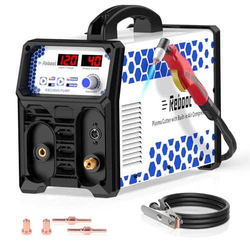
𝐁𝐔𝐈𝐋𝐓-𝐈𝐍 𝐀𝐈𝐑 𝐂𝐎𝐌𝐏𝐑𝐄𝐒𝐒𝐎𝐑, 𝐙𝐄𝐑𝐎 𝐄𝐗𝐓𝐄𝐑𝐍𝐀𝐋 𝐔𝐍𝐈𝐓𝐒 𝐍𝐄𝐄𝐃𝐄𝐃: Integrated high-efficiency air pump eliminates the need for separate air compressors. Start cutting immediately with simplified setup
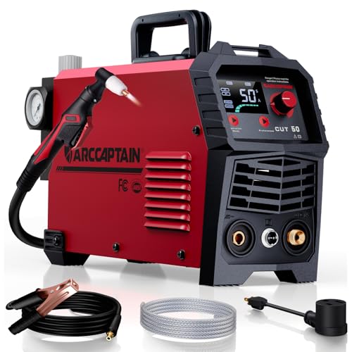
【Powerful Cutting Ability】Switch effortlessly between 110V and 220V for home or workshop use. Achieve professional 1/2" clean cuts on steel, aluminum, and copper with advanced LGBT technology. Perfect for DIY projects and heavy-duty tasks. Recommended maximum cutting thickness: 12mm @ 35A / 110V / 55 PSl; 18mm @ 50A / 220V / 75 PSI. Note: Requires compressed air (compressor sold separately).

CUTTING THICKNESS UP TO 20MM: Featuring a brand-new MCU technology upgrade, the plasma cutter machine has a high degree of internal integration, combining full digitalization for more precise control of cutting parameters such as current and voltage. This results in better cutting effects and improved stability. Cutting thickness: Quality 12mm (1/2"), maximum 20mm (3/4").
Hose and Coupler Sizing
Long or undersized hoses cause pressure drop. Restrictive quick-connects can create the same problem even when the hose itself is large enough. Follow the cutter manual’s minimum internal diameter.
As one current example, the Powermax45 SYNC manual calls for at least a 3/8-inch internal-diameter gas hose for runs shorter than 50 feet and at least a 1/2-inch internal diameter for runs from 50 to 100 feet. That is a model-specific example, not a universal sizing rule.
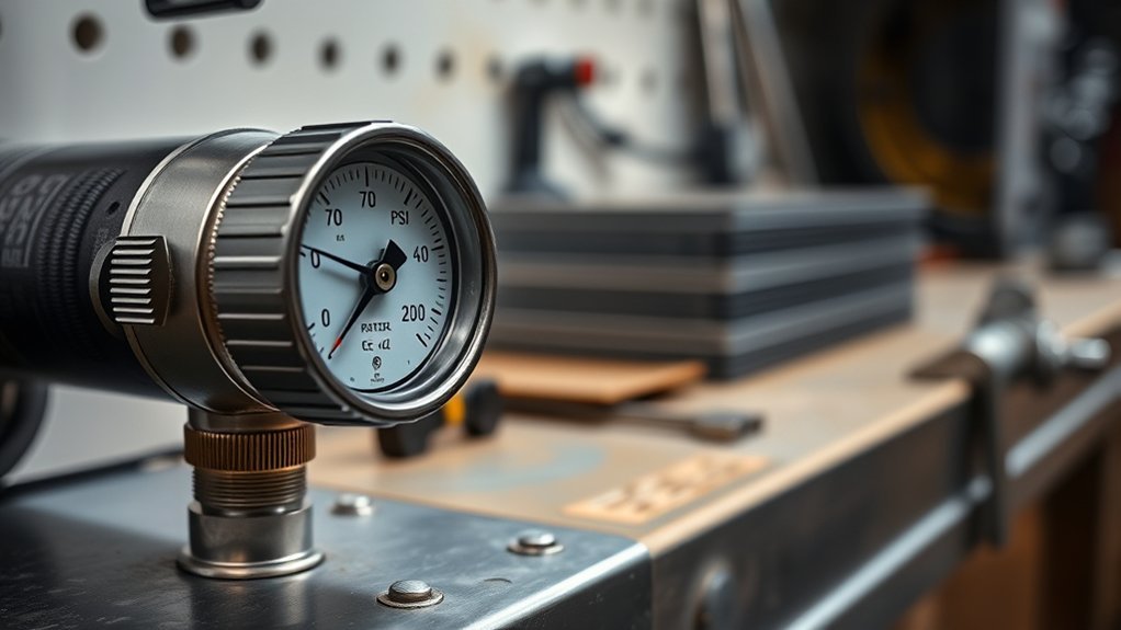
Pro Tip: Install a pressure gauge at the plasma-cutter inlet after the final filter or dryer. Compare its reading at idle with the reading during gas flow. A large drop points to a restricted hose, small coupler, clogged filter, leak, or compressor that cannot keep up.
Filtration and Air Quality for Cleaner Cuts

Correct pressure and flow cannot overcome badly contaminated air. Water, oil mist, rust, scale, and compressor debris can disturb the arc, damage internal components, and shorten nozzle and electrode life.
Clean, dry, oil-free air is one of the most effective ways to protect cut quality, consumables, the torch, and the plasma power supply.
Hypertherm’s air-quality guidance explains that moisture and impurities can reduce consumable life, compromise cut quality, and damage the torch or power supply.
A practical compressed-air treatment system may include:
- Compressor tank and receiver drainage: drain according to the compressor manufacturer’s schedule and more often when moisture collects quickly.
- Water separator or particulate filter: removes liquid water, rust, scale, and larger debris.
- Coalescing filter: captures fine oil aerosol and small liquid droplets when properly sized.
- Desiccant or refrigerated dryer: lowers moisture content in humid shops or demanding continuous-use systems.
- Final filter near the cutter: catches contaminants introduced by long shop-air piping and provides last-stage protection.
Install each component in the direction shown by its manufacturer and size it for the required airflow. An undersized or saturated filter may clean the air but create enough pressure loss to starve the cutter.
If the plasma-cutter manual specifies an ISO 8573-1 compressed-air purity class, meet that class rather than guessing. ISO 8573-1 classifies compressed-air contamination by particles, water, and oil. As of July 2026, ISO 8573-1:2010 remains the published edition, although ISO has begun work on a revision.
Note: A built-in cutter filter is not always a complete air-drying system. In warm, humid, oily, or heavily used air systems, the cutter manufacturer may recommend additional upstream filtration.
Products Worth Considering

Desiccant Air Dryer System: Engineered with a compressor desiccant air filter dryer system that effectively traps water vapor, oil aerosols, and dirt particles from the air supply. This unit functions as a reliable air line dryer, helping to prevent moisture-related damage to pneumatic tools and ensuring smoother operation for workshop projects.
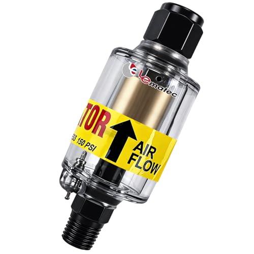
Moisture Protection: 1-micron reusable element removes air compressor oil and water from compressed air systems; essential for precise spray painting and plasma cutting

【Designed for Drying】The Desiccant Air Dryer allows the Air to be Thoroughly Dried and Cleaned before it Enters your Pneumatic Tools. The Desiccant Beads need to be Added to the Metal Bowl. When it needs to be Replaced, the Beads will Change from Blue to Pink.
Setting and Adjusting Air Pressure on Your Machine

Set pressure only after the compressor, hose, couplers, filters, dryer, and cutter inlet are connected correctly. Check the manual to determine whether you are adjusting incoming supply pressure, an internal manual regulator, or an electronic pressure setting.
Verify Supply Pressure
- Turn the cutter off and allow the compressor to reach its normal cut-out pressure.
- Drain collected moisture and inspect the air filters.
- Check hoses for kinks, crushed sections, leaks, and undersized fittings.
- Connect an inlet gauge after the final filter when the manual permits it.
- Turn on the cutter and select gas-test, purge, pressure-check, or the equivalent mode.
- Point the torch away from yourself and others before starting continuous gas flow.
- Confirm that inlet pressure stays within the manual’s range while air is flowing.
When pressure is correct at idle but falls below specification during flow, do not immediately turn the regulator higher. First locate the restriction or lack of compressor capacity.
Use Automatic or Manual Pressure Correctly
Many newer cutters set gas pressure automatically according to the torch, process, amperage, consumable or cartridge, and torch-lead length. Leave automatic mode enabled for normal cutting unless the manual directs otherwise.
On a cutter with a manual regulator:
- Unlock or pull the regulator knob if required.
- Start gas flow using the manufacturer’s pressure-setting mode.
- Adjust to the specified flowing pressure or indicator zone.
- Lock the knob after adjustment.
- Never exceed the listed maximum inlet pressure.
If a manually changed pressure causes a fault or worsens the cut, return it to the factory default before adjusting other variables.
Test and Fine-Tune
Make test cuts on scrap with the same material, thickness, surface condition, and consumables planned for the job.
- Start with the manual’s default pressure, amperage, cut mode, and consumables.
- Confirm a clean work-clamp connection on bare metal.
- Make a straight cut at the recommended speed and standoff.
- Inspect dross, kerf, bevel, striation lines, arc sound, and whether the cut fully severs the plate.
- Change only one variable at a time.
- Record the successful setup for later jobs.
Do not use air pressure as the first correction for every poor cut. Worn consumables, incorrect speed, excessive standoff, weak work-clamp contact, low amperage, wet air, and damaged torch parts can produce similar symptoms.
Run a Pressure-Drop Test
A simple pressure-drop test can separate compressor problems from cutter problems:
- Record the pressure at the cutter inlet while the system is idle.
- Start gas-test mode and record the flowing pressure.
- Continue the test long enough for the compressor to restart.
- Watch whether the pressure recovers, remains steady, or continues falling.
- Check pressure before and after filters if gauges are available and the filter manufacturer permits it.
A rapid drop usually points to a restriction, leak, or inadequate initial supply setting. A slow, continuing decline after the compressor starts often indicates that the compressor cannot deliver the required sustained airflow.
Performance Indicators: Dross, Kerf, and Cut Quality

Cut quality reflects the full process, not air pressure alone. Evaluate pressure together with airflow, air quality, amperage, speed, torch height, consumables, work-clamp contact, and material condition.
Dross as a Diagnostic Clue
Dross is resolidified metal left on the cut edge. Minimal dross that chips away easily usually means the setup is close. Heavy or strongly attached dross can come from several causes.
- Heavy, soft bottom dross: commonly linked to slow travel speed, excessive heat, poor molten-metal ejection, or an incorrect process setup.
- Thin, hard bottom dross: commonly linked to excessive travel speed, inadequate amperage, excessive standoff, or an arc that is lagging behind the torch.
- Top spatter: may result from poor piercing technique, excessive standoff, worn consumables, or an unsuitable speed.
The Hypertherm dross troubleshooting guide emphasizes that speed and process settings are major causes of dross. Confirm pressure and airflow, but do not adjust PSI repeatedly while ignoring speed or consumable condition.
Kerf Width Signals
Kerf width is the gap created by the plasma arc. A kerf that grows wider during a job may point to worn consumables, rising heat, changing torch height, slow travel, or an unstable gas supply. A narrow kerf with hard bottom dross may indicate excessive speed or arc lag.
Use calipers when repeatability matters. Record material thickness, amperage, consumables, speed, standoff, inlet pressure, and compressor behavior. A repeatable square edge is more useful than a universal PSI target.
Cut Edge Appearance
A good hand-plasma cut has a consistent edge, predictable striation lines, limited bevel, and little firmly attached dross.
- Rough or uneven edge: check speed, air quality, consumables, torch motion, and work-clamp contact.
- Strong bevel: check torch angle, standoff, travel direction, consumables, and speed.
- Sputtering or hissing arc: check moisture, pressure stability, filters, hose restrictions, and consumable condition.
- Rapid consumable wear: check air contamination, piercing technique, consumable compatibility, amperage, and manufacturer pressure settings.
- Incomplete severance: check speed, amperage, cut capacity, work-clamp contact, consumables, and sustained airflow.
Troubleshooting Air Pressure Problems
Return manually adjusted pressure to the manufacturer default before troubleshooting. Then test one cause at a time.
| Symptom | Likely causes | What to do |
|---|---|---|
| Low-pressure warning or no arc | Low flowing inlet pressure, disconnected supply, blocked hose, clogged filter, or inadequate compressor output | Use gas-test mode, read pressure at the cutter inlet, inspect the full air path, and compare compressor SCFM with the manual |
| Pressure is correct at idle but low during flow | Undersized hose, restrictive coupler, clogged filter, leak, or weak compressor recovery | Measure after filtration, shorten or enlarge the hose where required, replace restrictive fittings, and repair leaks |
| Arc sputters or hisses | Moisture, oil, unstable pressure, dirty filter, worn consumables, or damaged torch parts | Drain the air system, service filtration, confirm flowing pressure, and inspect the torch and consumables |
| Heavy bottom dross | Slow speed, inadequate airflow, wet air, low amperage, worn nozzle, or cutting beyond rated capacity | Run a speed test, verify sustained SCFM, dry the air, and compare the material with the machine’s cut chart |
| Wide or changing kerf | Worn nozzle, changing torch height, slow speed, excess heat, or unstable gas supply | Inspect consumables, stabilize torch motion, confirm inlet pressure, and adjust one variable at a time |
| High-pressure warning | Supply regulator set too high, faulty regulator, or incorrect manual pressure adjustment | Stop cutting, reduce inlet pressure to the manual’s range, return process pressure to default, and service a faulty regulator |
| Consumables wear quickly | Dirty air, moisture, incorrect parts, poor piercing method, excessive pilot-arc use, or an out-of-range setting | Improve filtration, follow pierce guidance, install the correct consumables, and confirm factory pressure settings |
Maintenance Tips to Protect Consumables and Equipment

A stable air supply protects the compressor, cutter, torch, nozzle, electrode, and finished edge. Follow the service intervals in both the compressor and plasma-cutter manuals.
- Drain the compressor receiver and water separators at the specified interval.
- Check filter bowls for water, oil, dirt, cracks, or discoloration.
- Replace filter and dryer elements at the specified service interval or pressure drop.
- Inspect hoses for leaks, crushed sections, heat damage, and undersized fittings.
- Check the regulator and inlet gauge for stable readings under flow.
- Inspect the electrode, nozzle, swirl ring, shield, cartridge, and retaining cap before important cuts.
- Keep the torch lead straight enough to avoid sharp kinks and airflow restrictions.
- Disconnect input power and gas before maintenance that exposes internal parts.
| Task | When to do it | Why it matters |
|---|---|---|
| Drain receiver and water traps | At the manufacturer’s interval and whenever water accumulates | Reduces moisture entering the filters and cutter |
| Check flowing inlet pressure | Before a new setup and when performance changes | Confirms that the cutter receives enough air under load |
| Inspect filters and dryers | At the filter maker’s interval and more often in humid or oily systems | Prevents contamination and excessive pressure drop |
| Leak-check hoses and fittings | Monthly and after changing the air system | Stops wasted air and pressure loss during cutting |
| Inspect consumables | Before precision work and whenever cut quality drops | Worn parts can imitate an air-pressure problem |
| Record proven settings | After successful test cuts | Makes material, amperage, speed, consumables, and air behavior repeatable |
Frequently Asked Questions
What PSI should I run my plasma cutter at?
Use the pressure listed in the manual for your exact cutter. Many published portable-cutter requirements are near 80–90 PSI at a stated airflow, but some machines require a 90–120 PSI or 110–120 PSI incoming range. Check pressure while air is flowing at the cutter inlet.
What is the air pressure for a 40 amp plasma cutter?
There is no universal 40-amp setting. Official 40-amp-class specifications vary by model and may include both a minimum flow requirement and a separate incoming pressure range. Use the model manual rather than choosing PSI from amperage alone.
Will a 20 gallon air compressor run a plasma cutter?
Possibly. A 20-gallon compressor can run some small cutters when its delivered SCFM at the required PSI meets or exceeds the cutter’s demand. The tank may support short cuts even when the pump is undersized, but pressure will fall during longer cuts if the pump cannot recover fast enough.
How does air pressure affect plasma cutting?
Air pressure and flow affect arc stability, molten-metal ejection, cooling, and whether the cutter can maintain its intended process. Pressure that is too low, too high, or unstable can cause faults or poor cuts, but speed, amperage, height, consumables, and air quality must also be checked.
Should plasma cutter air pressure be set static or while air is flowing?
Set or verify it while air is flowing. Use gas-test, purge, or pressure-check mode when available. Static pressure can look correct even when a small hose, clogged filter, restrictive coupler, leak, or undersized compressor causes pressure to fall under load.
Why does my plasma cutter sputter even when the gauge shows the right PSI?
The gauge may show compressor or static pressure instead of flowing pressure at the cutter inlet. Sputtering can also come from moisture, oil, dirty filters, unstable compressor recovery, worn consumables, a damaged torch, or poor work-clamp contact.
Do I need an air dryer for plasma cutting?
Every plasma cutter needs air that meets its specified moisture and oil limits. A water separator and suitable filters may be enough in some dry, low-use shops. Humid climates, long air lines, frequent cutting, or oily compressor systems may require a desiccant or refrigerated dryer.
Does thicker metal require higher plasma cutter air pressure?
Not automatically. Thicker metal normally requires the correct amperage, consumables, speed, standoff, and piercing method. Keep inlet pressure and airflow within the cutter manual’s specifications instead of raising PSI only because the plate is thicker.
What if my plasma cutter has a built-in air compressor?
A cutter with an integrated compressor normally does not need an external shop-air connection. Follow its manual for filter service, duty cycle, temperature, altitude, and moisture limits. Do not connect external pressure unless the manufacturer specifically provides and approves that option.
Can I use oxygen or another gas instead of compressed air?
Use only gases approved in the exact cutter manual. Some air-plasma systems also permit nitrogen or another named process gas. Never substitute oxygen, a flammable gas, or an unlisted mixture because it can create a fire, explosion, equipment-damage, or process-control hazard.
Conclusion
The correct plasma cutter air pressure is the machine-specific inlet and process pressure that remains stable while the required volume of clean gas is flowing. Do not rely on a universal PSI chart, compressor tank size, or metal thickness alone.
Start with the manual. Compare the cutter’s required SCFM with the compressor’s delivered SCFM at the same pressure. Measure inlet pressure after the hose, fittings, filters, and dryer. Use automatic pressure mode when provided, keep the gas clean and dry, and return manual adjustments to default before troubleshooting.
When a cut has dross, bevel, sputter, or an inconsistent kerf, inspect the whole process: airflow, pressure stability, moisture, consumables, speed, amperage, standoff, torch condition, and work-clamp contact. A stable air system and controlled test cuts will produce safer, cleaner, and more repeatable results.
Sources
- Hypertherm Powermax45 SYNC Operator Manual — current inlet-pressure, minimum-flow, gas-test, filtration, automatic-pressure, hose-sizing, and troubleshooting guidance.
- Hypertherm Powermax30 XP Data Sheet — official 4 SCFM at 80 PSI specification for a small portable cutter.
- Miller Spectrum 375 X-TREME Owner’s Manual — official 5.0 SCFM and 90–120 PSI supply specification.
- Hypertherm: Plasma Cutter Performance and Air Quality — effects of moisture, oil, and downstream contamination on cut quality and equipment life.
- OSHA 29 CFR 1910.252 — hot-work fire prevention, ventilation, container, and welding-and-cutting safety requirements.
- ISO 8573-1:2010 — current published compressed-air purity classification for particles, water, and oil.