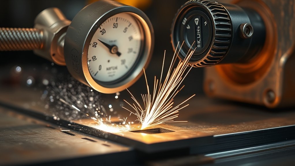
The minimum air pressure for a plasma cutter is not one universal PSI number. Your cutter needs the pressure and airflow stated in its owner’s manual, measured at the correct location while air is flowing. Using a copied setting from another machine can cause pressure faults, unstable cutting, heavy dross, damaged consumables, or excessive inlet pressure.
Quick Answer
The correct minimum air pressure is the lowest flowing inlet pressure listed in your plasma cutter manual. Depending on the model, that may be 60 psi, 80 psi, 85 psi, or another value. Set it during purge, meet the required airflow at that pressure, and never exceed the machine’s maximum inlet rating.
Key Takeaways
- Use the PSI and airflow specification for your exact plasma cutter and torch.
- Check pressure while the machine is purging air, not while the system is idle.
- Do not use 35 to 40 psi as a universal minimum. Many cutters require 60 psi or more.
- Choose a compressor by delivered CFM or SCFM at the required pressure, not tank size alone.
- Keep the air clean, dry, regulated, and oil-free, and never exceed the cutter’s maximum inlet pressure.
What’s in This Article
- Why Minimum Air Pressure Matters in Plasma Cutting
- Recommended PSI for Common Plasma Cutters
- Matching Amperage, Pressure, and Material Thickness
- Compressor PSI, SCFM, and Duty Cycle Requirements
- Setting Regulators and Managing Pressure Drop
- Air Filtration, Drying, and Line Sizing
- Troubleshooting Pressure and Cut-Quality Problems
- Pressure Setup and Test-Cut Procedure
- Frequently Asked Questions
- Safe Next Steps for Better Plasma Cuts
- Sources
At a Glance
| Time Required | About 10 to 20 minutes for inspection, purge testing, and a test cut |
| Difficulty | Beginner to intermediate |
| Tools Needed | Owner’s manual, air compressor, regulator and gauge, suitable hose and fittings, filtration, PPE, and matching scrap metal |
| Cost | Usually no added cost if the system already has adequate regulation and filtration; replacement gauges, hoses, or filters vary by setup |
Why Minimum Air Pressure Matters in Plasma Cutting

Compressed air does more than push debris away from the cut. It becomes the plasma gas, helps shape the arc, removes molten metal from the kerf, and supports torch cooling. The cutter needs enough pressure and airflow to perform those jobs throughout the cut.
Pressure that falls below the machine’s specified minimum can trigger a low-air fault, interrupt the arc, reduce cutting capacity, or leave heavy dross. Poor airflow can also contribute to high consumable temperatures and shorter component life.
Excess pressure is not better. It can create turbulent gas flow, accelerate nozzle wear, affect arc shape, and exceed the safe rating of the machine’s filter bowl or internal components.
The safe minimum is the flowing-pressure value in your own plasma cutter manual, not a universal 35 psi rule.
Understand the Three Pressure Readings
Plasma-cutter pressure discussions become confusing because people may be describing different measurement points:
- Compressor tank pressure: The pressure stored inside the receiver tank. This is not the pressure that automatically reaches the cutter.
- Cutter inlet pressure: The pressure available where the hose enters the plasma cutter, preferably measured while gas is flowing.
- Internally regulated pressure: The lower pressure created inside some cutters after the incoming air passes through the machine’s regulator.
A machine may require 80 to 110 psi at its inlet while regulating the gas internally to a lower working pressure. That does not mean the cutter can operate with only the lower pressure supplied at the hose.
Warning: Never exceed the maximum inlet pressure listed by the manufacturer. Hypertherm, for example, warns that more than 135 psi can create an explosion hazard at the Powermax45 SYNC filter bowl. Disconnect electrical power and shut off the air supply before servicing regulators, filters, hoses, or torch parts.
Recommended PSI for Common Plasma Cutters
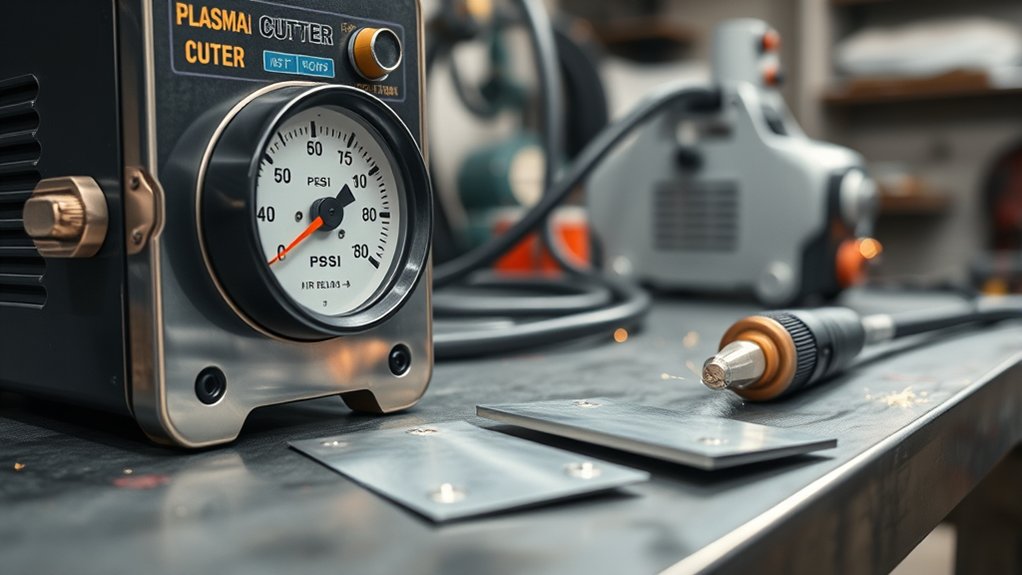
There is no single recommended PSI range that covers every plasma cutter. Verified manufacturer specifications show why you need the manual for your model.
| Plasma Cutter | Verified Air Requirement | What It Shows |
|---|---|---|
| Eastwood Versa-Cut 40 | 5 to 7 CFM; 60 psi throughout the manual’s listed cut chart; do not operate below 60 psi | Pressure does not automatically increase with every material thickness. |
| Legacy Everlast PowerPlasma 50 | About 60 to 65 psi for the older blowback-torch design | The familiar 60 to 65 psi recommendation is model-specific, not universal. |
| Titanium Plasma 65 | 4.2 CFM at 80 to 110 psi supply pressure | A cutter may need substantially more inlet pressure than 60 psi. |
| Hypertherm Powermax45 SYNC | Minimum 450 scfh at 85 psi for cutting; optimum flowing inlet pressure of 110 to 120 psi; maximum 135 psi | Minimum, optimum, and maximum pressure can all be different values. |
Products Worth Considering
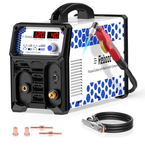
𝐁𝐔𝐈𝐋𝐓-𝐈𝐍 𝐀𝐈𝐑 𝐂𝐎𝐌𝐏𝐑𝐄𝐒𝐒𝐎𝐑, 𝐙𝐄𝐑𝐎 𝐄𝐗𝐓𝐄𝐑𝐍𝐀𝐋 𝐔𝐍𝐈𝐓𝐒 𝐍𝐄𝐄𝐃𝐄𝐃: Integrated high-efficiency air pump eliminates the need for separate air compressors. Start cutting immediately with simplified setup
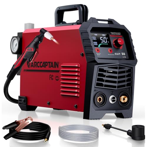
【Powerful Cutting Ability】Switch effortlessly between 110V and 220V for home or workshop use. Achieve professional 1/2" clean cuts on steel, aluminum, and copper with advanced LGBT technology. Perfect for DIY projects and heavy-duty tasks. Recommended maximum cutting thickness: 12mm @ 35A / 110V / 55 PSl; 18mm @ 50A / 220V / 75 PSI. Note: Requires compressed air (compressor sold separately).

CUTTING THICKNESS UP TO 20MM: Featuring a brand-new MCU technology upgrade, the plasma cutter machine has a high degree of internal integration, combining full digitalization for more precise control of cutting parameters such as current and voltage. This results in better cutting effects and improved stability. Cutting thickness: Quality 12mm (1/2"), maximum 20mm (3/4").
How to Find the Correct PSI
- Find the specifications or gas-supply section in the owner’s manual.
- Identify the required pressure and airflow together. Do not separate the PSI from the CFM, SCFM, or SCFH requirement.
- Check whether the number describes compressor output, cutter inlet pressure, or internal regulated pressure.
- Look for a maximum inlet-pressure rating.
- Check whether pressure must be measured while gas flows.
- Follow any separate specifications for cutting, gouging, or marking.
Machines with automatic gas controls may set internal pressure for you. You still need to supply enough pressure and flow at the inlet for the automatic system to work correctly.
How Material Thickness Affects the Setup
Material thickness usually changes amperage, travel speed, consumable choice, pierce technique, and torch standoff. It does not automatically justify changing air pressure.
Use the pressure shown in the manufacturer’s cut chart. Lower the pressure for thin sheet only when the manual specifically allows it. The same rule applies to steel, stainless steel, aluminum, copper, and other electrically conductive metals.
Aluminum does not have one universal lower-pressure setting. Alloy, thickness, amperage, torch design, consumables, and the cutter’s gas-control system all affect the correct setup.
Adjusting for Altitude and Hot Conditions
A compressor may deliver less usable air at higher altitude or in demanding hot-weather conditions. Watch the flowing inlet pressure and the compressor’s recovery time during a long purge or cut.
Do not compensate by raising the regulator beyond the cutter’s approved range. Use a compressor with adequate delivered airflow under your local conditions, reduce unnecessary restrictions, and follow any altitude guidance supplied by the compressor and plasma-cutter manufacturers.
Note: A correct static gauge reading does not prove that the system can maintain pressure while cutting. Always confirm the reading during purge or another manufacturer-approved flow test.
Matching Amperage, Pressure, and Material Thickness
Set air pressure from the machine’s manual or cut chart. Then match amperage, consumables, speed, and standoff to the material. This order prevents you from using pressure changes to hide a problem caused by another setting.
Thickness-Based Amperage
Thin material generally needs less cutting current and faster travel. Thick material normally needs more current, a slower travel speed, and enough time for the arc to penetrate the plate.
Use a nozzle or cartridge rated for the selected amperage. Running high current through an undersized nozzle can damage consumables and produce poor cut quality even when the air supply is correct.
Before changing pressure, check these items:
- Is the amperage suitable for the material thickness?
- Is the nozzle, tip, or cartridge rated for that amperage?
- Is the torch moving too slowly or too quickly?
- Is the torch at the correct angle and standoff?
- Is the work clamp attached to clean, bare metal?
- Are the consumables correctly assembled and in good condition?
Setting Priorities by Cutting Condition
| Cutting Condition | Adjust First | Pressure Guidance |
|---|---|---|
| Thin sheet | Lower amperage, correct fine-cut consumables if available, and faster travel | Keep the manual or cut-chart setting unless it provides a separate low-amperage pressure. |
| General cutting | Recommended amperage, consumable, speed, and standoff | Use the specified flowing inlet pressure. |
| Thick plate | Higher approved amperage, slower travel, proper piercing method, and edge starting when practical | Do not raise pressure unless the cut chart calls for it. |
| Arc drops during a cut | Check flowing pressure, grounding, consumables, supply voltage, and duty cycle | Restore the specified pressure rather than guessing at a higher value. |
| High altitude or long hose run | Check compressor capacity, leaks, fittings, filters, and hose restriction | Stay between the manufacturer’s minimum and maximum inlet limits. |
Compressor PSI, SCFM, and Duty Cycle Requirements
A suitable compressor must deliver the cutter’s required airflow at the required pressure for as long as you plan to cut. Tank capacity helps provide temporary reserve, but the pump must eventually replace every cubic foot of air the torch uses.
Products Worth Considering

BUILT-IN AIR COMPRESSOR: With this plasma cutter machine, you're ready to cut as soon as you connect it to a power source, no additional air compressor needed. Designed for effortless outdoor work, it also offers compatibility with external compressors for versatile use

𝐁𝐔𝐈𝐋𝐓-𝐈𝐍 𝐀𝐈𝐑 𝐂𝐎𝐌𝐏𝐑𝐄𝐒𝐒𝐎𝐑, 𝐙𝐄𝐑𝐎 𝐄𝐗𝐓𝐄𝐑𝐍𝐀𝐋 𝐔𝐍𝐈𝐓𝐒 𝐍𝐄𝐄𝐃𝐄𝐃: Integrated high-efficiency air pump eliminates the need for separate air compressors. Start cutting immediately with simplified setup

COMPLETE BUILT-IN AIR SYSTEM: Equipped with an integrated high-performance air pump, this plasma cutter eliminates the need for an external air compressor—simply plug into power and start cutting with no extra equipment or complicated setup required
How to Size the Compressor
- Find the plasma cutter’s required CFM, SCFM, or SCFH and the pressure attached to that rating.
- Read the compressor’s delivered-air rating at the same pressure or a higher pressure.
- Choose a compressor with useful output margin so it is not forced to run at its limit during every cut.
- Check the compressor’s duty cycle and thermal limits.
- Confirm that your hose, filters, regulator, and fittings can pass the required flow.
Do not compare a compressor’s maximum tank pressure with the plasma cutter’s airflow requirement. A compressor advertised at 150 or 175 psi may still deliver too little CFM for continuous plasma cutting.
Verified Compressor Examples
- The Titanium Plasma 65 specifies 4.2 CFM at 80 to 110 psi.
- The Eastwood Versa-Cut 40 specifies 5 to 7 CFM and uses 60 psi in its cutting chart.
- The Hypertherm Powermax45 SYNC specifies 450 scfh at 85 psi as the minimum for cutting.
A compressor that barely meets the stated flow may support short hobby cuts but run continuously or lose pressure during longer work. More delivered airflow gives the compressor time to recover and helps maintain stable inlet pressure.
Will a 20-Gallon Compressor Work?
A 20-gallon compressor can run some plasma cutters if its pump delivers enough air at the specified pressure. The tank may provide enough reserve for short cuts even when pump output is close to the cutter’s demand.
For longer cuts, watch the inlet gauge as the compressor reaches its cut-in pressure. Stop if the pressure falls below the machine’s minimum, the cutter displays a low-air fault, or the compressor exceeds its allowed duty cycle.
Setting Regulators and Managing Pressure Drop

Pressure drop occurs when air moves through hoses, filters, dryers, quick-connects, valves, and fittings. A system can show high pressure at rest and still starve the torch when gas begins flowing.
How to Set Dynamic Pressure
- Inspect the system: Check hoses, couplers, filters, drains, and regulator connections for damage or leaks.
- Start the compressor: Let the tank reach its normal cut-out pressure.
- Set the upstream supply: Use the inlet range stated in the plasma-cutter manual.
- Activate purge mode: Use the machine’s gas-test or purge function when available.
- Read the gauge under flow: Check pressure at the cutter inlet or the manufacturer-specified gauge.
- Correct pressure drop: Repair leaks or replace restrictive components if pressure falls below specification.
- Lock the regulator: Secure the adjustment after the correct flowing pressure is stable.
If static pressure is 100 psi but flowing inlet pressure falls to 75 psi, the system has a 25 psi dynamic drop. Raising the regulator may not solve the underlying problem if the compressor, hose, or fitting cannot pass enough air.
Common Sources of Pressure Loss
- Long or undersized air hose
- Small automotive-style quick-connects
- Partially closed valves
- Clogged filter elements
- Saturated dryers
- Leaking couplers or cracked hose
- A regulator that is too small for the required flow
- A compressor that cannot maintain the cutter’s air demand
Pro Tip: Place an inline gauge at the plasma cutter inlet after external filters and dryers. This shows the pressure that reaches the machine instead of the higher pressure available at the compressor.
Air Filtration, Drying, and Line Sizing

Plasma cutters need clean, dry, regulated, oil-free air. Moisture, oil, vapor, rust, and particles can reduce cut quality, damage internal parts, and shorten consumable life.
The Titanium Plasma 65 manual calls for a filter, regulator, pressure gauge, dryer, shutoff valve, and suitable couplers. It also warns against using an inline oiler because oil in the cutting air causes poor results.
For the Powermax45 SYNC, Hypertherm specifies clean, moisture-free gas and recommends that compressor air comply with ISO 8573-1:2010 Class 1.4.2. Treat this as a model-specific specification rather than a universal filter recipe.
Practical Filtration Order
A shop system may use the following order when the cutter manual allows it:
- Compressor and receiver tank
- Aftercooling or enough pipe length for moisture to condense
- Water separator with a working drain
- Air dryer when humidity or continuous use requires one
- Particle or coalescing filtration matched to the required airflow
- Regulator and gauge
- Plasma cutter
Do not install a fine filter that cannot pass the cutter’s required airflow. Every filter has a pressure drop that normally increases as the element becomes dirty.
Hose and Fitting Size
Use the hose diameter specified by the manufacturer. Eastwood requires at least a 3/8-inch inside-diameter air-supply line for the Versa-Cut 40. Other machines may use different inlet fittings or flow requirements.
For long runs, calculate line size from total flow, pressure, fittings, and acceptable pressure drop. Avoid assuming that one hose-size rule fits every compressor and cutter.
Pro Tip: Drain the compressor tank and inspect the final filter bowl before each cutting session. A sudden increase in collected water can signal a failed drain, saturated dryer, or humid-air problem.
Troubleshooting Pressure and Cut-Quality Problems

Low or unstable pressure can cause poor cutting, but dross, bevel, and arc failure are not proof of an air problem by themselves. Check the entire cutting system before changing the regulator.
| Symptom | Possible Causes | Checks |
|---|---|---|
| Low-air fault or no arc start | Low inlet pressure, closed valve, leak, clogged filter, inadequate compressor, or incorrect consumable assembly | Purge the machine, verify flowing pressure, inspect the air path, and check the torch parts. |
| Arc starts and then stops | Pressure sag, poor work connection, excessive standoff, worn consumables, low voltage, or duty-cycle shutdown | Watch the gauge during flow, clean the clamp location, inspect the torch, and check warning lights. |
| Heavy bottom dross | Travel too slow, amperage too low, worn nozzle, excessive standoff, or inadequate airflow | Confirm pressure first, then compare speed, current, consumables, and standoff with the cut chart. |
| Incomplete cut | Material exceeds capacity, speed too fast, low amperage, pressure loss, poor ground, or damaged consumables | Verify the material rating and all recommended cutting parameters. |
| Wide or irregular kerf | Worn nozzle, incorrect standoff, slow travel, excessive or unstable pressure, or poor torch angle | Inspect the nozzle or cartridge and confirm pressure under flow. |
| Rapid consumable wear | Wet or oily air, incorrect pressure, excessive pilot-arc time, piercing too close, or mismatched consumables | Service the air system and compare the torch setup with the manufacturer’s instructions. |
After a pressure problem, inspect the electrode, nozzle, swirl ring, retaining cap, and any cartridge or shield parts. Replace damaged parts as a set when the manufacturer requires it.
Do not continue production cutting until the machine maintains its specified flowing pressure through a full compressor cycle.
Pressure Setup and Test-Cut Procedure
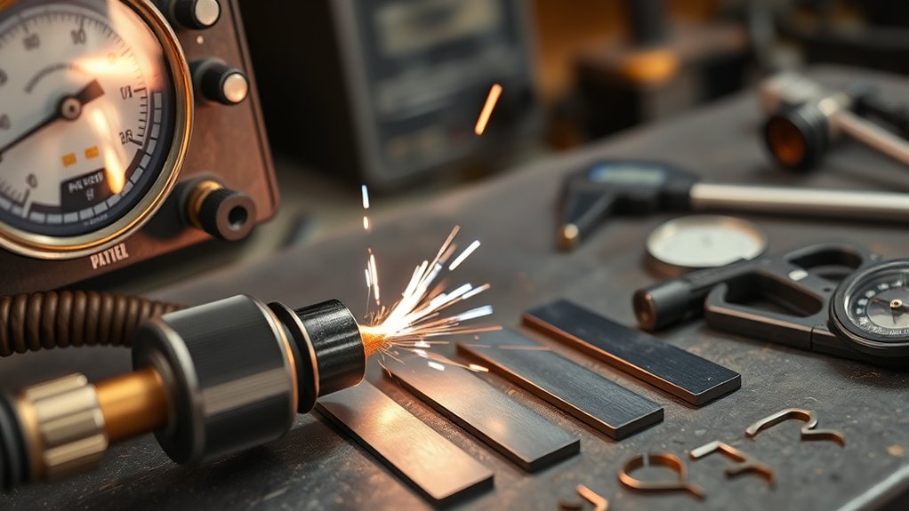
Use scrap from the same material and thickness as the finished part. A structured test separates pressure problems from amperage, speed, standoff, and consumable problems.
- Read the manual: Record the minimum and maximum inlet pressure, required airflow, recommended amperage, consumable type, and standoff.
- Prepare the air supply: Drain the compressor, inspect filters, and remove any oiler from the plasma-cutter air line.
- Check for leaks: Pressurize the system and inspect hoses, couplers, valves, and fittings.
- Set pressure under flow: Activate purge mode and adjust the inlet pressure to the manufacturer’s specification.
- Run a straight test cut: Use the recommended amperage, torch angle, standoff, and travel speed.
- Inspect the result: Check full penetration, dross, edge angle, kerf width, top spatter, and arc stability.
- Change one variable: Correct pressure first if it is outside specification. Otherwise adjust speed, current, standoff, or consumables one at a time.
Keep a simple settings record for repeat jobs. Note the machine, consumables, material, thickness, amperage, pressure measurement point, travel speed, and cut result.
Note: If the compressor pressure steadily falls during purge, test cuts will not solve the problem. Restore enough compressor output and airflow capacity before continuing.
Frequently Asked Questions
What PSI should I run my plasma cutter at?
Use the flowing inlet-pressure specification in the manual for your exact model. One cutter may use 60 psi, while another requires 80 to 110 psi or a minimum of 85 psi. Do not copy a setting until you confirm the measurement point and maximum inlet rating.
Is 35 to 40 psi enough for a plasma cutter?
It is not a safe universal minimum. Some machines may regulate gas internally near that range, but many require at least 60, 80, or 85 psi at the inlet. Use the owner’s manual and verify pressure while air flows.
Will a 20-gallon air compressor run a plasma cutter?
It can run some plasma cutters if its pump delivers enough CFM at the required pressure. Tank size only determines how much reserve air is available. Watch flowing inlet pressure and compressor recovery during longer cuts.
What compressor does the Titanium Plasma 65 require?
The official Titanium Plasma 65 manual specifies a compressor capable of supplying 4.2 CFM at 80 to 110 psi. A compressor with additional delivered-air capacity can provide better recovery for longer cuts, but 10 CFM at 100 psi is not the machine’s stated minimum.
Should plasma-cutter pressure be set static or flowing?
Set and confirm pressure while air flows. Use purge or gas-test mode when available. Static pressure can look correct even when the hose, filters, fittings, regulator, or compressor cause a large pressure drop under load.
Can wet air damage plasma-cutter consumables?
Yes. Moisture, oil, and particles can cause poor starts, rough cuts, internal contamination, and shorter consumable life. Drain the compressor, maintain filters, and add suitable drying equipment when shop conditions require it.
Can too much air pressure hurt a plasma cutter?
Yes. Excess pressure can disturb gas flow, accelerate nozzle wear, affect cut quality, and exceed the safe rating of filters or internal components. Never exceed the maximum inlet pressure in the manual.
Should I change air pressure for different material thicknesses?
Only when the manufacturer’s cut chart tells you to. Thickness more commonly changes amperage, travel speed, consumables, and standoff. Some cutters use one pressure across a wide thickness range, while automatic systems control gas internally.
Warning: Plasma cutting exposes you to electric shock, intense light, sparks, hot metal, fumes, fire, and compressed-gas hazards. Follow the machine manual, provide suitable ventilation, remove combustible materials, and wear appropriate eye and face protection, hearing protection, gloves, flame-resistant clothing, and footwear. Use only gases approved by the manufacturer.
Safety Disclaimer: This article provides general information about plasma-cutter air pressure. Always follow your machine manual, workplace rules, and applicable safety standards. Consult a qualified welding, cutting, electrical, or compressed-air professional when you are unsure about the equipment or installation.
Safe Next Steps for Better Plasma Cuts
Start with the owner’s manual rather than a generic PSI chart. Record the required airflow, minimum inlet pressure, recommended operating range, maximum inlet pressure, and correct measurement point.
Set pressure while gas flows, confirm that the compressor can maintain it, and keep the air clean, dry, and oil-free. When cut quality changes, inspect pressure, airflow, filters, leaks, grounding, consumables, amperage, speed, and standoff before changing settings at random.
A stable, manual-compliant air supply gives the torch the best chance to produce clean edges, reliable starts, and reasonable consumable life without exposing the machine to unsafe pressure.
Sources
- Harbor Freight Titanium Plasma 65 Owner’s Manual – verifies the 4.2 CFM at 80 to 110 psi requirement, air-supply components, moisture warning, and troubleshooting guidance.
- Eastwood Versa-Cut 40 Instructions – verifies the 60 psi cut chart, minimum pressure warning, 5 to 7 CFM requirement, and 3/8-inch minimum supply-line size.
- Hypertherm Powermax45 SYNC Minimum Inlet Pressure and Gas Flow – verifies minimum pressure and flow requirements for cutting, gouging, and marking.
- Hypertherm Powermax45 SYNC Maximum Inlet Pressure – verifies the optimum flowing-pressure range and 135 psi maximum.
- Hypertherm Gas Supply Quality Guidance – supports clean, moisture-free gas, filtration, and air-quality recommendations.
- OSHA 29 CFR 1910.133 Eye and Face Protection – supports eye, face, flying-particle, molten-metal, and harmful-radiation protection requirements.