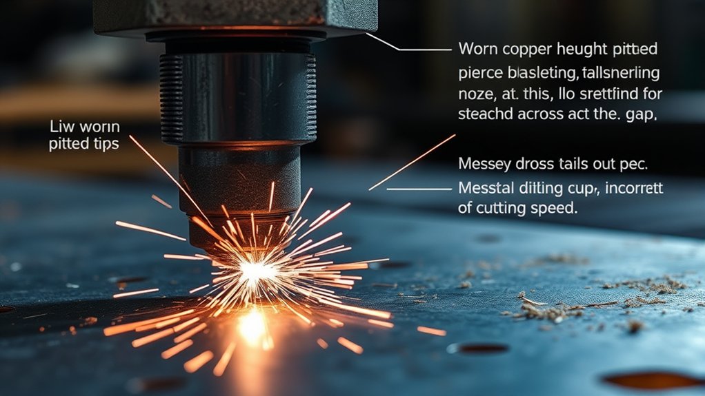
Like a worn drill bit tells on sloppy feeds and speeds, your plasma tip reveals parameter and maintenance errors. You run consumables past spec, swap them too early, or mix the wrong nozzle/electrode set. Assembly tolerances get ignored, and gas or coolant flow goes unchecked. Height control drifts, pierces start too low, and cut speed stretches the arc. Dirt raises resistance and heat. You can stop the spiral—once you know which failure modes to verify next.
Using Consumables Until They Blow
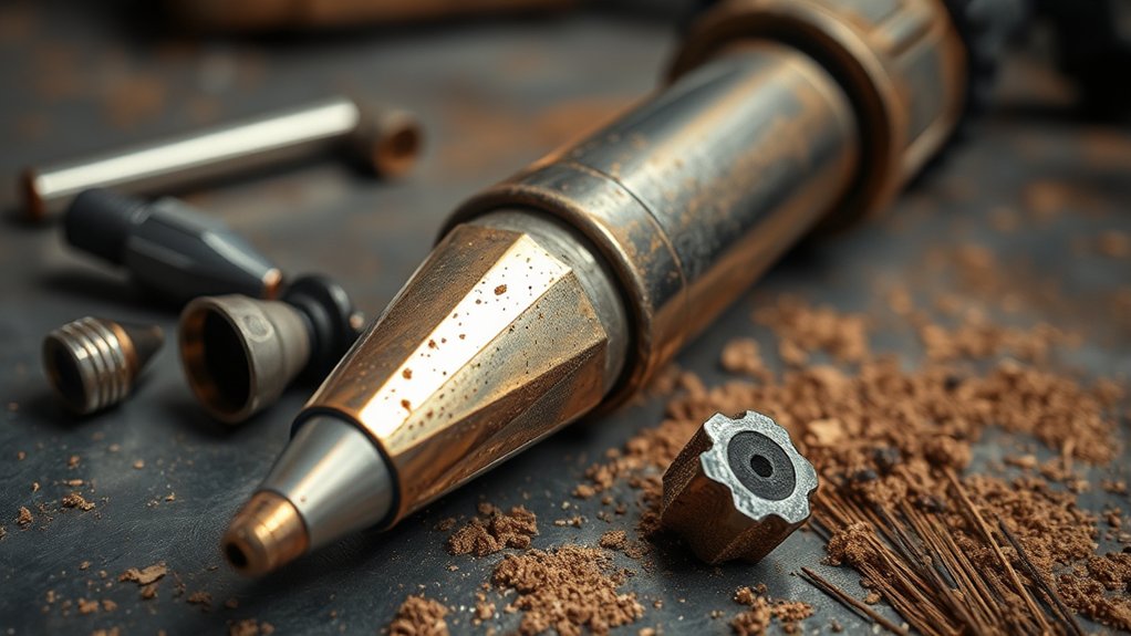
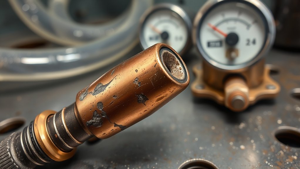
Although a consumable can still strike an arc when it’s beyond spec, running it “until it blows” accelerates failure modes that damage the torch and destabilize the cut. You’re exposing the nozzle, electrode, and shield to thermal runaway, double-arcing, and molten spatter intrusion, which propagates to the torch body and cables.
Treat worn consumable detection as a control point: listen for tonal shift or sputter, watch for arc color drifting toward green/white, and verify torch height fluctuation—each indicates tip orifice erosion and electrode pit growth.
Treat consumable wear as a control point: tonal shifts, green/white arc, and height wobble signal critical erosion.
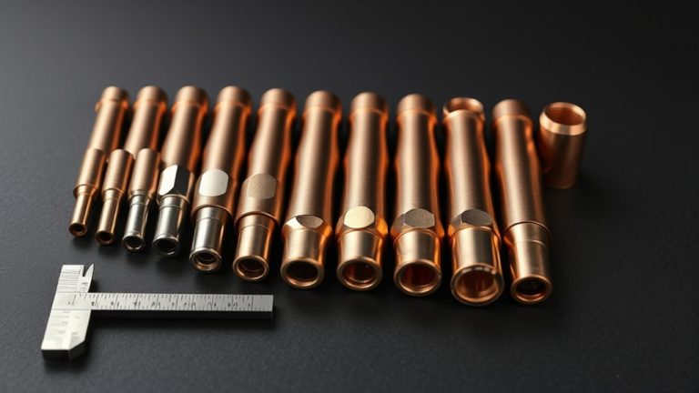
Implement operational efficiency strategies that prevent catastrophic end-of-life events. Standardize periodic inspections of the stack-up (nozzle, electrode, swirl ring, shield) against spec dimensions and surface finish.
Log average life by material, thickness, amperage, duty cycle, and gas quality; trend deviations to trigger earlier changeouts. Define life limits in work instructions so operators replace parts at calculated wear thresholds, not failure.
This preserves cut quality, protects metal components, and maintains predictable throughput.
Changing Consumables Too Soon
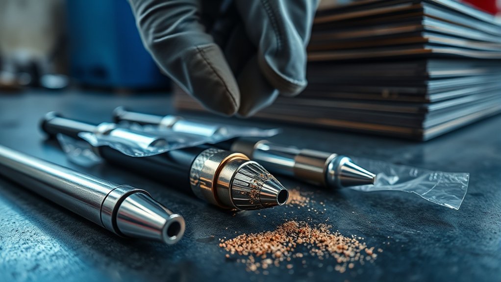
Running parts to failure isn’t the only cost driver—swapping them early inflates spend and masks process issues.
You reduce consumable lifespan when you discard nozzles, electrodes, and swirl rings on time-based cycles instead of condition. Set an inspection frequency tied to arc-on hours and cut count, then make go/no-go decisions by evidence.
Evaluate nozzles under magnification. Replace for gouges, ovality, or bell-mouth that affects kerf and arc constriction; keep serviceable parts in use.
For electrodes, measure the hafnium pit. A deep or cratered pit signals end-of-life; a shallow, intact pit indicates remaining service. Document thresholds in your work instruction.
Treat gas swirl rings as durable components. Replace only for cracks, burns, or swollen bores; otherwise, clean contamination and return to service.
Record findings to trend performance.
Regular condition-based evaluations extend life, stabilize cut quality, and lower operating cost without risking unplanned failures. Use data, not the calendar.
Using the Wrong Parameters and Parts for the Job
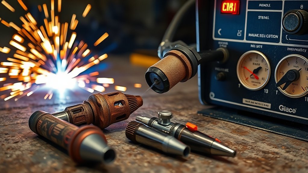
Even minor deviations from specified parameters accelerate tip erosion and destabilize the arc column. When you ignore consumable compatibility—material type, thickness, and nozzle rating—you increase heat loading on the orifice and swirl ring, which drives premature wear.
The operator’s manual isn’t optional; it’s the control document for selecting nozzles, electrodes, and shields that match the workpiece and amperage settings.
Running above the nozzle’s rating, especially beyond ~95%, overheats the constricting orifice, enlarges it, and weakens arc constriction. The result is sloppy cuts, increased dross, and shortened consumable life.
Undersetting current can be just as harmful, extending arc-on time and promoting double-arcing during pierce.
Apply the manufacturer’s cut charts: match nozzle size to material thickness, set amperage settings within the specified window, and verify gas pressure and travel speed accordingly.
When parameters align with the job, you preserve tip geometry, maintain arc stability, and achieve consistent edge quality with fewer changeouts and lower operating cost.
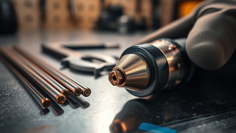
Assembling the Torch Incorrectly
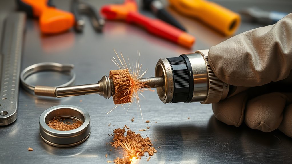
If torch components aren’t assembled to spec, you compromise electrical contact and disturb gas flow, which accelerates tip wear and destabilizes the arc. Mis-seated electrodes, skewed nozzles, or a loose retaining cap create high-resistance interfaces and asymmetric gas paths. The result is micro-arcing, double-arcs, and uneven cooling that erodes the orifice.
Enforce torch alignment: verify the assembly order, confirm each consumable seats fully, and tighten to the manufacturer’s torque or “snug” standard to prevent movement under backpressure.
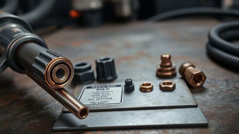
Apply contamination prevention at every step. Assemble in a clean area, keep threads and mating faces free of dirt, and handle parts with clean gloves. Don’t use grease. Any petroleum residue can carbonize, track current, and trigger destructive arcing. Use only minimal O-ring lubricant specified by the OEM to avoid clogging gas passages.
Before powering up, perform a visual and tactile check: concentric nozzle-to-electrode fit, undamaged O-rings, and unobstructed gas paths. These controls stabilize the arc and extend consumable life.
Neglecting Routine Maintenance
Correct assembly won’t save a torch that you never service. Without preventive maintenance, contaminants accumulate on nozzles, electrodes, and retaining caps, accelerating tip erosion and destabilizing the arc.
Dirt in threads and mating surfaces increases resistance, causing localized heating, erratic current transfer, and premature wear. You’ll also see degraded kerf quality and more dross as debris disrupts gas paths inside the torch body.
Follow a maintenance schedule tied to arc-on hours and consumable changes. At each interval, disassemble the front end, wipe components with lint-free swabs and approved cleaners, and verify that threads, seats, and O-rings are free of residue and nicks.
Inspect contact surfaces for pitting and discoloration; replace out-of-tolerance parts rather than stretching service life. Reassemble to spec torque to preserve concentricity and sealing.
Skipping these steps allows contamination to compound, leading to runaway thermal damage, sudden consumable failure, and avoidable downtime, repairs, and material scrap.
Not Checking Gas and Coolant Flow
Although the torch may be assembled correctly, failing to verify gas pressure and coolant flow creates thermal and electrical instability that destroys tips fast. You need stable gas flow and adequate coolant levels to keep arc energy and component temperatures within specification. Low gas pressure weakens arc constriction, degrading cut quality and eroding the orifice. Excessive pressure can destabilize the arc column, causing double-arcing and rapid tip pitting. Set and lock regulators to the manufacturer’s pressure window, then confirm with a calibrated gauge at the torch inlet.
Perform daily checks: validate gas flow rate under load, inspect filters and dryers, and purge lines to eliminate contamination that seeds arc wander and tip oxidation.
Monitor coolant levels and verify actual coolant flow using sight glasses or flow switches; insufficient flow drives overheating, annealing copper and damaging insulators. Trend data—pressure, flow, and temperature—to detect drift. Correct leaks, replace clogged filters, and restore cooling capacity before resuming cuts.
Piercing Too Low, Cutting Speed Errors, and Arc Stretching
You’ll mitigate tip wear by setting correct piercing height—typically 1.5–2.0× cut height—to prevent spatter and arc snuffing.
You must hold cutting speed within the equipment’s specified window; too slow causes low-speed dross and widened kerfs, while too fast drives bevel and narrow kerfs.
To prevent arc stretching and nozzle damage, maintain proper standoff and initiate arcs at the plate edge, then verify parameters through routine inspection and adjustment.
Correct Piercing Height
Precision in piercing height sets the baseline for consumable longevity and cut quality. Apply disciplined piercing techniques to hold the torch at the ideal height—typically 1.5–2× the cut height—before shifting to cut height.
If you pierce too low, spatter backfills the nozzle, overheats the orifice, and can snuff the arc, accelerating wear and degrading edge fidelity. Too high, and the arc elongates, destabilizing transfer and risking misfires.
Calibrate torch height control to pierce at programmed stand-off, then descend after a verified pierce delay. Use edge starts when feasible to reduce arc time in the puddle and mitigate arc stretching.
For interior features, program lead-ins and lead-outs that keep the arc moving away from the nozzle face. Validate with cut-voucher inspections: check orifice roundness, spatter witness marks, and edge bevel as acceptance criteria.
Optimized Cutting Speed
With pierce height set correctly, you must control cutting speed and stand-off to prevent the same failure modes from reappearing mid-cut. Piercing too low still drives spatter and arc snuffing, eroding orifices early. Use 1.5–2× cut height for pierce, then shift to the specified cut height and maintain it. Cutting speed optimization is mandatory: too slow produces low-speed dross accumulation and molten blowback; too fast narrows the kerf, bevels edges, and overheats tips. Arc stretching appears when stand-off increases during motion, loading the nozzle thermally and electrically.
| Symptom | Likely Cause | Corrective Action |
|---|---|---|
| Heavy dross | Speed too slow | Increase IPM; verify amperage |
| Beveled edge | Speed too fast | Reduce IPM; match nozzle rating |
| Narrow kerf | Over-speed | Decrease speed; stabilize THC |
| Spatter on tip | Low pierce height | Set 1.5–2×; follow manual |
Prevent Arc Stretching
Three variables drive arc stability and tip life: pierce height, cut speed, and stand-off. Set pierce height to 1.5–2× the cutting height; piercing too low induces spatter and arc snuffing that erode the nozzle and electrode.
Apply arc stability techniques: verify torch height with your THC, index for material thickness, and confirm voltage setpoints. Cutting speed errors compound wear—too fast narrows kerf and bevels edges; too slow creates low‑speed dross and heat loading. Maintain programmed speeds and validate with test cuts and edge angularity checks.
Prevent arc stretching by holding correct stand-off; excessive distance elongates the arc and burns the nozzle.
Use nozzle protection strategies: edge-start whenever possible, program lead-outs to avoid lingering in the cut, and inspect height routinely to adjust for material variations.
Frequently Asked Questions
How Does Ambient Humidity Affect Plasma Tip Lifespan?
Ambient humidity shortens plasma tip lifespan by raising moisture content in the gas stream, intensifying corrosion effects and arc instability. You’ll see micro-pitting, oxide buildup, double-arcing, and accelerated orifice erosion. Mitigate with desiccant dryers, dew-point monitoring, and corrosion-resistant consumables.
Can Power Supply Quality or Surges Wear Tips Faster?
Yes. Power supply quality directly affects tip wear. Power fluctuations degrade arc stability, accelerate erosion, and cause microcracking. Maintain voltage stability with regulated supplies, surge protection, proper grounding, and IEC/UL-compliant equipment. Log events, verify ripple limits, and perform failure analysis on prematurely pitted tips.
Do Different Gas Mixtures Impact Tip Bevel and Dross?
Absolutely—gas composition affects tip bevel and dross. Like a scalpel’s edge, you tune flow for standards. Use nitrogen/hydrogen for cleaner edges; air increases dross. Match tip geometry, current, and pressure to mitigate angularity, oxidation, and heat-affected wear.
How Does Torch Lead Length Influence Tip Wear?
Longer torch lead length increases resistance and inductance, degrading arc stability and accelerating tip erosion. You mitigate wear by minimizing torch length, using correct cable gauge, maintaining strain relief, and adhering to manufacturer bend-radius and duty-cycle standards verified through periodic resistance and voltage-drop checks.
Are Aftermarket Swirl Rings Compatible Without Accelerating Wear?
Yes—if you match OEM dimensions and materials, aftermarket compatibility won’t turbocharge wear. You verify gas chemistry, thermal rating, and clearances. Prioritize swirl ring durability, concentricity, and dielectric specs; otherwise you’ll induce catastrophic arc instability, micro-erosion, and nozzle blowout.
Conclusion
You control tip life more than you think. Most failures trace to avoidable causes: wrong parameters, sloppy assembly, skipped maintenance, or consumables run past spec. Set standoff, current, and gas per the OEM; verify swirl ring orientation; log nozzle/electrode changeouts; and confirm gas/coolant flow before every shift. One sobering data point: a 0.010-inch height error can double nozzle erosion rate. Treat the torch like a calibrated system—measure, document, and adjust—so tips fail on schedule, not by surprise.