Like links in a calibrated chain, each plasma cutter consumable has a defined role you can’t ignore. You’ll rely on the electrode to form the arc, the nozzle to focus it, and the swirl ring to stabilize gas flow. The retaining cap and shield cap align and protect critical paths. You’ll also track wear indicators, match nozzle sizes to amperage, and apply maintenance intervals—because the moment tolerances slip, cut quality and safety do too.
Overview of Plasma Cutter Consumables
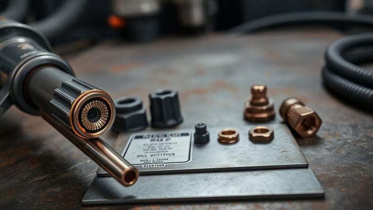
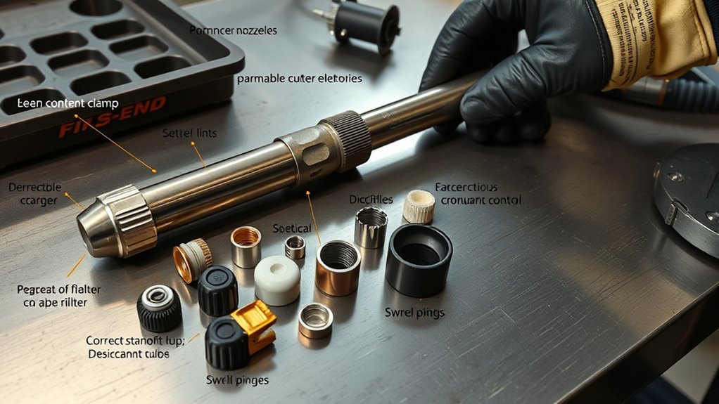
A plasma cutter’s consumables are a defined set of wear parts—electrode (typically copper with a hafnium insert), nozzle, swirl ring, retaining cap, and shield cap—that control arc formation, constriction, and gas delivery for compliant, repeatable cuts.
You manage these plasma cutter components as a system: the electrode establishes the arc, the nozzle constricts it for kerf accuracy, the swirl ring meters and imparts swirl to the gas stream for stabilization and nozzle cooling, and the retaining and shield caps secure and protect the flow path.
Apply consumable maintenance on a fixed inspection cadence: verify orifice integrity, confirm swirl ring ports are unobstructed, and ascertain caps seat to manufacturer torque.
Replace high-wear items—electrode and nozzle—within the typical one-to-three-hour duty window or sooner if cut quality degrades.
Standardize part numbers, gas purity, and amperage-to-nozzle sizing to maintain process capability.
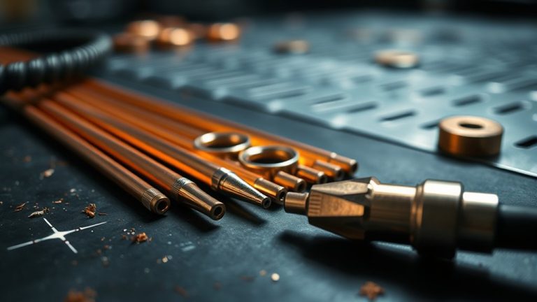
Electrode: Role and Wear Indicators
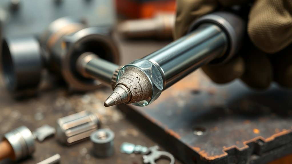
You use the electrode—copper with a hafnium emitter—on the negative output to conduct current and establish a stable, centered plasma arc.
Monitor the hafnium pit as a wear indicator; once pit depth reaches 1.0–1.6 mm, you should remove the electrode from service.
Replace on schedule to prevent arc instability, protect the nozzle, and maintain cut quality and system efficiency.
Function in Arc Formation
While the torch cycles, the electrode—typically copper with a hafnium emitter—conducts current to initiate and sustain the plasma arc, stabilizing and centering it through the nozzle orifice.
You rely on this function for arc stability and cutting accuracy, so you must treat the electrode as a controlled-wear component in your process.
- Visualize the preflow: gas sweeps the tip, the pilot arc snaps to the hafnium point, and the main arc locks on center.
- Picture the pit forming: once depth reaches 1–1.6 mm, you replace the electrode to preserve energy density.
- See the arc column: a centered emitter reduces lateral wander, preventing nozzle damage and kerf deviation.
- Execute maintenance: inspect between cuts, and replace the electrode with the nozzle to keep parameters in spec and extend consumable life.
Hafnium Emitter Wear
Because the hafnium emitter initiates and sustains the arc at extreme temperatures, it’s the primary wear point in the electrode and the leading driver of consumable replacement intervals.
Hafnium properties—high melting point, electron emissivity, and arc stability—enable reliable ignition, but thermal cycling and high current density erode the emitter rapidly.
You should prioritize electrode maintenance with a defined inspection cadence. Verify pit formation at the emitter tip; when pits reach 1–1.6 mm depth, record the condition and remove the electrode from service.
Continuing operation with a depleted emitter degrades arc transfer, causes hard starts, and elevates risk to the nozzle and swirl ring.
Expect the electrode to be the fastest-wearing consumable, often reaching end-of-life within hours, depending on current, duty cycle, and gas quality.
Replacement Timing Guidelines
With the hafnium emitter established as the primary wear site, set replacement timing by measured pit depth, start performance, and run hours.
Use a disciplined wear assessment to define replacement frequency and protect cut quality. Replace the electrode when the pit reaches 1–1.6 mm, when arc starts degrade, or when scheduled hours elapse.
Coordinate electrode and nozzle changes to stabilize arc geometry and prevent collateral wear.
- Gauge pit depth: target removal at 1.0–1.6 mm to avoid misfires and double-arcing.
- Track starts: rising ignition difficulty signals depletion—retire the electrode.
- Log hours: under normal operation, plan swaps every few hours; verify against duty cycle.
- Pair replacements: install a new nozzle with the electrode to maintain concentricity.
Document inspections, trend pit growth, and adjust intervals to your process.
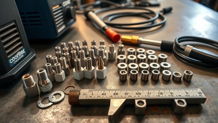
Nozzle: Sizing, Function, and Replacement
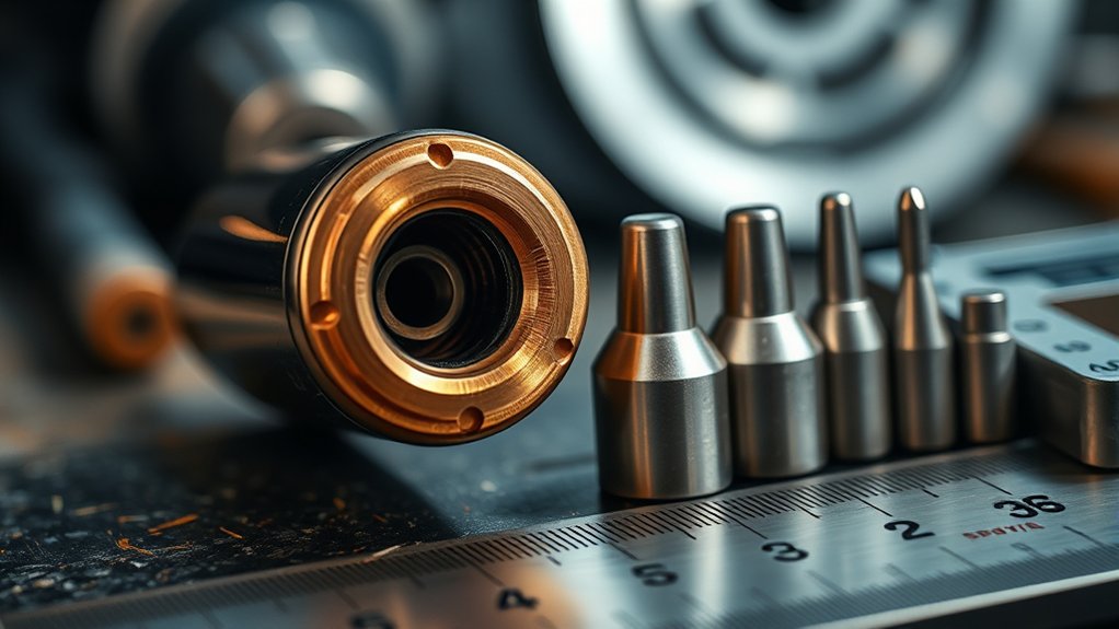
You’ll select nozzle size based on required kerf and task: use smaller orifices for precise cuts, larger for gouging, and match amperage per the torch’s specification.
Inspect the tip routinely for an enlarged or rough orifice; if kerf widens, edges degrade, or dross increases, treat it as out-of-tolerance.
Replace the nozzle with the electrode on a scheduled interval (every few hours of operation) or immediately when visual or cut-quality criteria fail.
Choosing Nozzle Size
Two factors govern nozzle selection: required kerf/detail and material thickness at the target amperage.
For standards‑based nozzle selection and cutting precision, match the orifice to the machine’s rated current and the workpiece. Smaller orifices constrict the arc, narrow kerf, and sharpen detail; larger orifices stabilize higher amperage for thick sections or purposeful gouging.
Always use sizes approved in your cutter’s chart to maintain flow, arc stability, and consumable life.
- Picture a fine orifice tracing filigree—tight kerf, crisp corners, minimal dross.
- See a mid-size nozzle slicing plate—balanced speed, stable arc, clean edge.
- Imagine a large nozzle on heavy steel—wide kerf, deep penetration, steady travel.
- Visualize mismatched sizing—ragged edges, blowouts, overheating.
Verify amperage-nozzle pairing, monitor gas flow, and lock in standoff to sustain consistent performance.
When to Replace
Although nozzle sizing drives kerf and detail, replacement timing hinges on wear indicators and process control. Use systematic nozzle maintenance to protect cut quality and throughput.
Prioritize wear detection at every shift start: inspect the orifice for enlargement, ovality, or nicks, and check spatter buildup on the face. Replace the nozzle when the tip hole grows beyond nominal, edges degrade, or dross increases despite correct parameters.
Nozzles wear faster than other parts due to arc exposure; set inspection intervals accordingly. For consistency, replace the nozzle with the electrode as a matched set, since both degrade together and affect arc stability.
Verify you’re using the correct size: smaller orifices for precision cutting, larger for gouging. After replacement, recalibrate amperage, gas flow, and standoff to restore process capability.
Swirl Ring: Gas Flow Control and Maintenance
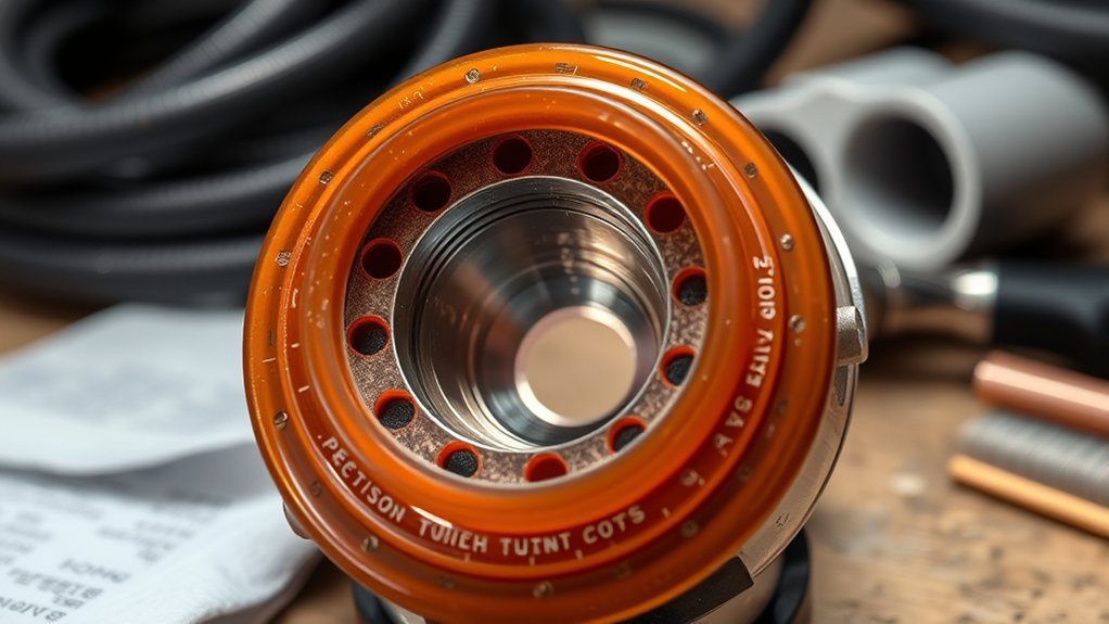
Because the swirl ring meters and imparts a controlled vortex to the plasma gas around the electrode, it’s critical to arc stability, cut precision, and consumable life. You rely on swirl ring functionality to regulate gas velocity, angle, and distribution, which directly drives plasma arc stability and thermal balance.
By cooling and centering the jet, the ring limits nozzle erosion and preserves kerf quality through consistent flow.
Follow a repeatable control-and-maintenance routine:
- Visualize the gas as a helical sheath: uniform spiral flow stabilizes the arc column and narrows divergence.
- Picture the nozzle face staying cooler: the swirl extracts heat, delaying copper softening and spatter adhesion.
- See a crisp, striation-free edge: steady swirl eliminates arc wander and micro‑turbulence.
- Imagine a clean bore: debris-free ports keep metering precise.
Inspect the ring for cracks, glazing, or ovalized ports each torch service. Replace it every fifth electrode change, or immediately if damage appears.
Verify correct orientation and seating torque to prevent leaks and maintain spec gas dynamics.
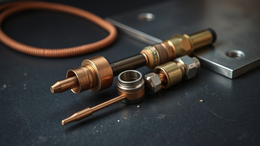
Retaining Cap and Shield Cap: Protection and Alignment
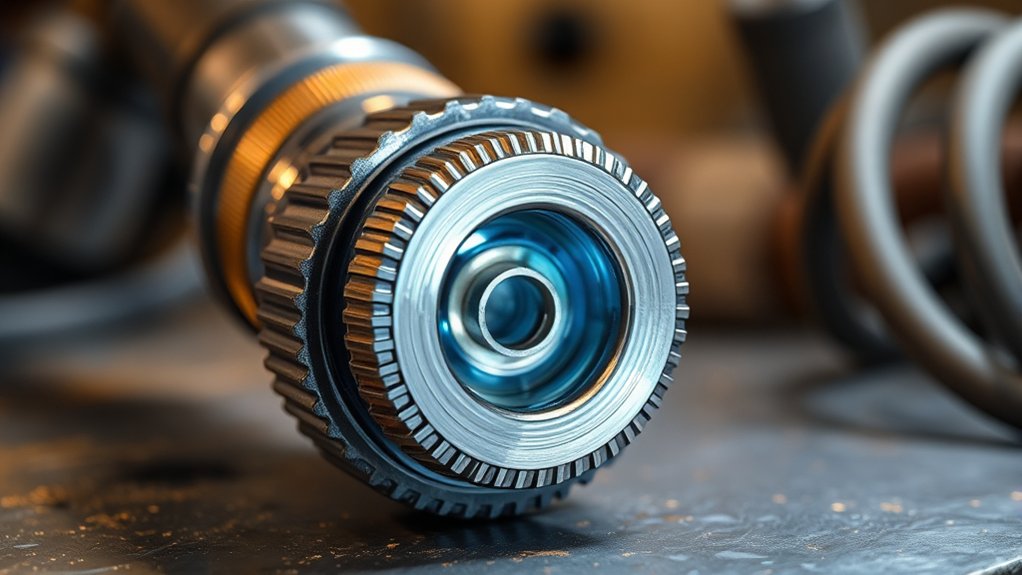
With swirl control established, you lock that performance in place with the retaining cap and shield cap. The retaining cap secures the consumable stack—electrode, nozzle, swirl ring—in a concentric, repeatable position, maintaining torch geometry under heat and pressure.
An inner retaining cap seals the coolant path to prevent leaks that destabilize arc energy and erode components. You verify seating torque per manufacturer specification to avoid misalignment, gas bypass, or coolant loss.
The shield cap provides a sacrificial barrier against sparks, molten metal, and abrasive debris, preserving the nozzle orifice and electrode face from incidental impact. It also stabilizes standoff dynamics by managing exit flow around the arc zone.
Implement a defined inspection interval: check both caps for thread wear, cracks, heat checking, spatter bridging, O‑ring condition, and sealing surfaces.
Replace compromised parts immediately. Using distorted or burnt caps degrades cut quality, increases dross, and elevates risk of blowbacks that damage upstream consumables and disrupt process control.
Tips to Maximize Consumable Lifespan
Even before arc start, set a maintenance cadence that prioritizes consumable health: log run time, inspect at defined intervals, and replace electrodes and nozzles before performance drifts—typically at 1–3 hours of use.
Apply maintenance techniques consistently and document changes to stabilize cut quality and cost.
- Calibrate parameters: set amperage, pierce delay, cut speed, and standoff per OEM specifications. Maintain correct torch-to-work distance to prevent double-arcing and nozzle ovalization.
- Control cleanliness: wipe and blow out the shield cap frequently to keep cooling passages clear. Clear airflow reduces thermal load, protecting nozzle orifice geometry and electrode inserts.
- Verify consumable quality: use model-specific electrodes, nozzles, shields, and retaining caps from reputable sources. Dimensional accuracy and metallurgy directly influence life and cut consistency.
- Inspect the stack: check swirl ring integrity, O-ring elasticity, and seating faces. Replace components showing cracks, burning, or swelling. Reassemble to torque guidance, then test on scrap to validate kerf, dross level, and arc stability.
Schedule routine audits to catch wear early and prevent premature failures.
Frequently Asked Questions
How Do Ambient Temperature and Humidity Affect Consumable Performance?
Ambient temperature and humidity directly alter consumable performance. You manage temperature effects to maintain arc stability and tolerance; you mitigate humidity impact to prevent moisture ingress, oxidation, and contamination. Implement storage controls, preheating, desiccants, and inspection per manufacturer specifications.
Are Aftermarket Consumables Compatible With My Torch Warranty?
Yes—often no. Many manufacturers void torch warranties with non-OEM parts. Review your manual’s aftermarket compatibility clause, warranty considerations, and approved consumables list. If allowed, document installation, maintain duty cycles, log part numbers, and keep traceable procurement records.
What Storage Methods Prevent Consumable Contamination or Oxidation?
Seal smartly: you store consumables in airtight, antistatic bags with desiccants, ensuring proper sealing and humidity control. You standardize handling, glove-up, purge containers with dry nitrogen, label lots, schedule inspections, and segregate copper from steel to stop oxidation.
How Do Cutting Gas Choices Impact Consumable Lifespan and Cut Quality?
Cutting gas selection dictates arc energy, oxidation, and dross formation, directly affecting consumable lifespan and cut quality. Use nitrogen or oxygen per material; maintain dew point ≤−40°C, purity ≥99.995%. Verify pressure, flow, swirl alignment, and gas sequencing per OEM parameters.
Can Software Settings Reduce Consumable Wear During CNC Cutting?
Yes—you can. Tune software optimization like a surgeon: adjust cutting speed, pierce height, dwell, lead-ins, and ramping. Use validated parameter tables, corner slowdown, kerf compensation, anti-dive. You’ll stabilize arcs, limit double-arcing, and extend consumable service life.
Conclusion
You’ve seen how electrodes, nozzles, swirl rings, retaining caps, and shield caps work as a system—and why disciplined replacement intervals matter. One data point underscores it: a worn nozzle can increase kerf width by up to 30%, degrading tolerance and rework rates. Apply OEM duty-cycle limits, verify gas quality (dew point ≤ −40°C), and log arc starts to forecast wear. Standardize inspections per 8-hour shift, torque per spec, and replace at wear limits to sustain cut quality and throughput.