
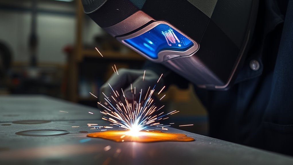
Arc length is one of the small adjustments that can make a large difference in weld quality. It affects arc voltage, bead shape, penetration, spatter, and how easy the puddle is to control. The correct distance depends on whether you are Stick, TIG, MIG, or flux-core welding, so one rule does not fit every process.
Quick Answer
Arc length in welding is the active gap between the electrode and the weld pool or workpiece. A steady, process-appropriate arc helps produce consistent voltage, penetration, and bead shape. Too much or too little distance can cause spatter, undercut, sticking, stubbing, contamination, or an uneven bead.
Key Takeaways
- Arc length is not the same as MIG stickout, electrode extension, or contact-tip-to-work distance.
- A longer arc normally requires more voltage, but the current response depends on whether the welder uses constant-current or constant-voltage output.
- Arc length influences heat distribution, but total heat input also depends on amperage, travel speed, and process efficiency.
- Stick, TIG, and MIG require different methods for setting and maintaining the correct distance.
- Use the machine chart, electrode instructions, welding procedure, and test beads rather than relying on one universal measurement.
At a Glance
| Time Required | A few practice beads before welding the final joint |
| Difficulty | Beginner to intermediate |
| Tools Needed | Welder, correct electrode or wire, matching scrap metal, wire brush, and welding PPE |
| Cost | Usually no added cost beyond normal consumables and scrap |
Warning: Welding can expose you to arc radiation, electric shock, hot metal, fire, and hazardous fumes. Wear a suitable welding helmet, gloves, flame-resistant clothing, and eye protection. Keep combustibles away and use ventilation or local exhaust that is appropriate for the metal, coating, filler, and work area.
What’s in This Article
- What Is Arc Length in Welding?
- Arc Length vs. Stickout and CTWD
- Why Arc Length Changes Voltage
- How Arc Length Affects Weld Quality
- Arc Length and Heat Input
- Set Arc Length for MIG, TIG, and Stick
- Practice Arc Length Control
- Fix Common Arc Length Problems
- Sources
- Frequently Asked Questions
- Conclusion
What Is Arc Length in Welding?

Arc length is the active gap across which the welding arc travels. In Stick and TIG welding, it is commonly described as the distance from the electrode tip to the workpiece or molten weld pool. In MIG and flux-cored welding, it is the gap from the melting end of the continuously fed wire to the puddle.
The gap is small, but changes in it can affect voltage, arc shape, shielding, bead width, and penetration. Miller’s guide to common welding terms explains that welding voltage controls arc length and that Stick, TIG, MIG, and flux-cored processes use different power-source characteristics.
A consistent arc does not guarantee a sound weld by itself. Current, voltage, travel speed, electrode type, wire feed speed, polarity, joint preparation, shielding, and torch or rod angle must also match the job. These variables are especially important when learning flux-core welding techniques.
Note: “Electrode tip” does not mean exactly the same thing in every process. A Stick rod becomes shorter as it burns, a TIG tungsten is nonconsumable, and a MIG wire continuously melts and feeds into the arc.
Arc Length vs. Stickout and CTWD
Beginners often use arc length, stickout, electrode extension, and contact-tip-to-work distance as if they mean the same thing. They do not. This difference matters most in MIG and flux-cored welding because changing the gun-to-work distance can change electrode extension and amperage without directly representing the true arc gap.
| Term | What It Measures | Why It Matters |
|---|---|---|
| Arc length | The active gap from the electrode’s arcing end to the work or puddle | Closely related to arc voltage, arc shape, and bead behavior |
| Electrode extension | The unmelted wire from the contact tip to the point where it melts | Changes electrical resistance and amperage in constant-voltage wire welding |
| Stickout | The wire length from the nozzle end to the point where the wire melts | May differ from electrode extension when the contact tip is recessed or protruding |
| Contact-tip-to-work distance | The distance from the MIG contact tip to the workpiece | Includes electrode extension plus the arc region and affects wire-welding current |
Miller’s explanation of stickout, electrode extension, and contact-tip-to-work distance notes that changing these distances can move a MIG weld outside its specified amperage range. Use the exact term shown in your machine manual or welding procedure.
Why Arc Length Changes Voltage
A longer arc normally requires more voltage to maintain the electrical discharge across the larger gap. A shorter arc operates at a lower voltage. That basic relationship applies broadly, but the way the welding machine responds depends on its output type.
Arc Length and Electrical Response
It is common to say that a longer arc has more resistance, but that explanation can become confusing when it is mixed with MIG electrode extension. The safer practical rule is that arc voltage tracks the active arc gap, while resistance heating in the unmelted wire is strongly affected by electrode extension.
This distinction explains why moving a MIG gun farther from the work can lower current even though a longer true arc is normally associated with higher voltage. The gun movement may have increased the unmelted wire length rather than only changing the arc gap.
Voltage Shifts in CC and CV Welding
| Power-Source Type | Common Processes | What Happens When Distance Changes |
|---|---|---|
| Constant current (CC) | Stick and TIG | Current stays near the selected value while arc voltage rises or falls as the operator changes arc length. |
| Constant voltage (CV) | Conventional MIG and many flux-cored setups | The power source holds voltage comparatively steady and rapidly changes current to help keep the continuously fed wire arc stable. |
For Stick welding, select the correct current range for the rod and position before judging arc length. A Stick welding amperage chart can provide a starting point, but the electrode package and machine manual should take priority.
How Arc Length Affects Weld Quality
Arc length affects the shape and direction of the arc, which then influences bead width, penetration pattern, spatter, undercut, porosity risk, and puddle control. The exact symptoms vary by welding process, electrode, transfer mode, and settings.
| Arc Condition | Common Signs | Likely Result |
|---|---|---|
| Too long | Wide or wandering arc, excess spatter, poor shielding, harsh sound, or undercut | Less directional control, uneven fusion, wider bead, and possible porosity or undercut |
| Correct range | Steady arc, controlled puddle, even bead width, and repeatable sound | More consistent bead profile, penetration, and tie-in |
| Too short | Stick rod freezes, MIG wire stubs into the puddle, or TIG tungsten touches the metal | Arc outages, high crown, irregular deposition, contact-tip problems, or tungsten contamination |
Do not diagnose the weld from arc length alone. Excess current, low current, incorrect polarity, poor travel speed, dirty metal, bad shielding, wrong work angle, or poor joint fit-up can produce similar symptoms.
Before welding galvanized steel, removing the coating from the immediate weld area may improve arc stability and reduce the amount of zinc entering the arc. Follow a safe procedure for removing zinc coating from galvanized steel, and control the dust created during removal.
Warning: Galvanized and zinc-bearing metals can produce zinc oxide fumes when heated. Removing some coating does not make the job fume-free. Identify all coatings, use suitable local exhaust or ventilation, follow your workplace exposure-control procedure, and never weld an unknown coating until it has been evaluated.
Arc Length and Heat Input
Arc length affects voltage, but it does not determine heat input by itself. The Welding Institute explains that arc energy depends on voltage, current, and travel speed. Heat input also accounts for the efficiency of the welding process.
Arc length can change voltage and heat distribution, but total heat input also depends on amperage, travel speed, and process efficiency.
In simple terms, increasing voltage or current can increase energy at the arc, while increasing travel speed reduces the energy delivered to each inch or millimeter of weld. The full relationship is explained in TWI’s guide to arc energy and welding heat input.
Heat Input Effects
A long arc may spread the arc over a wider area and reduce directional force into the joint even when measured voltage is higher. This can create a wider, flatter bead and less reliable penetration in some applications. That is different from saying the weld received less total energy.
A tight arc often produces a narrower, more focused arc pattern, but an excessively short arc can extinguish, stick, stub, or contaminate the electrode. Burn-through and distortion are more commonly controlled by correcting amperage, voltage, travel speed, joint fit-up, and time spent in one place.
Arc Length Control
- Set the machine from the electrode package, wire chart, approved procedure, or manufacturer recommendation.
- Use a stable body position so normal hand movement does not change the gap.
- Watch the leading edge of the puddle instead of staring only at the bright center of the arc.
- Change one variable at a time when troubleshooting.
- Confirm the result by checking bead shape, toe fusion, penetration where inspection is possible, and any applicable weld-quality requirements.
For MIG welding, coordinate voltage with wire feed speed rather than adjusting either setting at random. A MIG wire-speed and voltage chart can provide a starting range for test beads.
Set Arc Length for MIG, TIG, and Stick
Use the welding process—not one universal measurement—to choose your starting distance. The following ranges and methods are starting guidance only. Electrode type, wire diameter, transfer mode, joint design, material, position, and the welding procedure can require different settings.
| Process | Starting Guidance | Primary Control |
|---|---|---|
| Stick/SMAW | Keep the arc tight and generally no longer than the metal core diameter of the electrode; some rods require a shorter arc. | Feed the rod toward the puddle as it burns shorter. |
| TIG/GTAW | Keep a close, steady gap without touching the puddle. Tungsten size, cup access, joint shape, and procedure determine the exact distance. | Brace the torch hand and move it smoothly with the joint. |
| MIG/GMAW | Set voltage and wire feed from the machine chart. For many short-circuit mild-steel setups, about 3/8 inch is a common stickout starting point—not an arc-length measurement. | Maintain consistent gun distance and adjust voltage and wire feed as a matched pair. |
| Flux-cored/FCAW | Use the wire manufacturer’s recommended electrode extension because self-shielded and gas-shielded wires can require different distances. | Hold the specified extension and use the recommended drag or travel technique. |
Stick Welding Arc Length
Miller recommends that Stick arc length generally should not exceed the diameter of the electrode’s metal core. A 1/8-inch 6010 electrode held about 1/8 inch from the work is one example, not a universal setting. Electrode type and application still control the final distance.
As the rod burns, move the electrode holder gradually toward the work to maintain the gap. If you hold your hand in one fixed position, the arc becomes longer as the electrode gets shorter.
TIG Welding Arc Length
TIG requires a close and steady tungsten-to-work distance. Miller notes that changing TIG arc length directly changes voltage and can alter penetration consistency, bead profile, and weld color. Keep the tungsten from touching the puddle or filler rod.
If the tungsten contacts molten metal, stop and inspect it. Regrind or replace a contaminated tungsten before continuing when the procedure requires a clean, correctly shaped tip.
MIG Welding Arc Length
On conventional CV MIG equipment, voltage is the main setting associated with arc length. Wire feed speed mainly influences current and deposition rate, while electrode extension and CTWD also affect amperage. Start with the chart inside the wire-feed compartment or the machine manual.
Miller’s mild-steel MIG guidance identifies about 3/8 inch as a common stickout starting point for many short-circuit applications. Do not apply that number to every wire, transfer mode, material, or procedure.
Pro Tip: Make test beads on clean scrap that matches the final joint’s metal, thickness, position, and shielding setup. Change only one setting or technique variable between beads, then label each test so you can compare the results.
How to Practice Arc Length Control
- Prepare matching scrap: Clean the metal and arrange it in the same position as the final weld.
- Set a safe starting range: Use the machine chart, electrode label, wire data sheet, or approved procedure.
- Brace your body: Support your forearm or torch hand without placing skin or clothing where hot metal can reach it.
- Run a straight bead: Concentrate on maintaining the same gap and travel speed from start to finish.
- Inspect the result: Look for even width, smooth toes, controlled reinforcement, low spatter, and consistent appearance.
- Make one correction: Adjust distance, voltage, current, wire feed, or travel speed one at a time and run another bead.
Repeat the exercise until you can keep the arc stable while the Stick electrode shortens, the TIG torch crosses small surface changes, or the MIG gun moves along the joint.
Products Worth Considering

Premium welding training steel

Includes 2 pre-cut steel sheets that detach into 24 parts—weld them to build 2 hollow cubes and 2 dice.
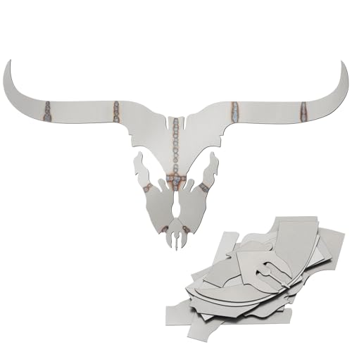
Complete Beginner-Friendly Welding Project:Everything You Need to Start; This all-in-one kit includes pre-cut 201 carbon steel plates designed to form an impressive deer head sculpture; It's the perfect hands-on way to practice and master TIG, MIG, Arc, or Stick welding techniques, turning theory into a tangible piece of art
Fix Common Arc Length Problems

| Problem | Possible Cause | Correction |
|---|---|---|
| Stick electrode freezes to the work | Arc is too short, amperage is too low, or the rod angle is poor | Increase the gap slightly, verify the rod’s current range, and maintain a stable travel angle |
| Stick weld has heavy spatter or undercut | Arc may be too long; current or travel speed may also be excessive | Shorten the arc, check amperage, and avoid moving too slowly at the toes |
| MIG wire repeatedly pushes into the puddle | Voltage may be too low for the wire feed, or the gun may be too close | Return to the chart settings, verify CTWD, and fine-tune voltage and wire feed together |
| MIG arc is irregular with poor penetration | Excess electrode extension, poor work connection, worn contact tip, or incorrect settings | Shorten the extension to the recommended range and inspect the tip, liner, drive rolls, and work clamp |
| TIG bead width or color changes | Arc length, torch angle, shielding, or travel speed is drifting | Brace the torch hand, maintain the gap, verify gas coverage, and keep travel steady |
| TIG arc becomes dirty or unstable after contact | The tungsten touched the puddle or filler metal | Stop, allow the torch to cool as required, and regrind or replace the contaminated tungsten |
- Watch the puddle: Track its leading edge, width, and tie-in at both toes.
- Listen by process: A stable sound should repeat consistently. MIG short-circuit welding often has a steady sizzle with occasional pops, while repeated stubbing signals a mismatch.
- Check the bead: Uneven width, high crown, undercut, heavy spatter, or poor toe fusion can reveal a technique or setting problem.
- Check equipment: Inspect the work clamp, leads, contact tip, liner, drive rolls, gas supply, electrode condition, and polarity.
- Practice deliberately: Repeat one correction at a time until the correct distance becomes a controlled movement rather than a guess.
Arc length is one of several linked variables. Learning the main welding parameters will help you separate arc-length problems from incorrect current, voltage, travel speed, angle, or electrode selection.
Products Worth Considering

7piece Fillet Weld Set Gage Rl Gauge
![Wire/Metal Sheet Thickness Gauge 229895 Welding Gage Plated Size Inspection Tool [NOT Cheap Stamping Version]](https://m.media-amazon.com/images/I/41Y5r3lOozL._SL500_.jpg)
Metal Thickness Gauge Function——The Thickness Gauge can helps you check metal sheet thickness or wire diameter before welding or working. By use this metal thickness template, you can get the thickness of your metal sheet, and that will help you weld better and avoid unnecessary errors.

Sources
- Miller — Five Steps to Improving Your Stick Welding Technique — Stick arc-length limits, sticking, spatter, undercut, and electrode control
- Miller — Common TIG Welding Problems — TIG arc-length effects, bead consistency, and tungsten control
- Miller — Understanding the Basics of MIG Welding for Mild Steel — MIG voltage, wire speed, stickout, angles, and setup
- Miller — Stickout, Electrode Extension, and Contact-Tip-to-Work Distance — Definitions and effects on wire-welding amperage
- TWI — Difference Between Heat Input and Arc Energy — Voltage, current, travel speed, and process-efficiency relationships
- OSHA 29 CFR 1910.252 — Welding-fume, ventilation, zinc-bearing metal, and general safety requirements
Frequently Asked Questions
What is arc length, and why is it important?
Arc length is the active gap between the electrode’s arcing end and the workpiece or weld pool. It matters because changes in that gap alter arc voltage, arc shape, shielding behavior, bead profile, penetration consistency, and puddle control.
What happens if your arc length is too long?
An excessively long arc can wander, spread the arc force, weaken shielding, and increase spatter, undercut, porosity risk, or bead width. The exact symptoms depend on the process, electrode, transfer mode, current, voltage, and travel speed.
What happens if your arc length is too short?
A too-short Stick arc can extinguish or freeze the rod to the work. MIG wire may stub into the puddle, and TIG tungsten may touch and become contaminated. A short arc does not automatically mean excessive heat; current, voltage, travel speed, and dwell time must also be checked.
How do you know your arc length is correct?
The arc should remain stable while the puddle and bead width stay consistent. The finished bead should show controlled reinforcement and even toe tie-in without repeated sticking, stubbing, heavy spatter, undercut, or sudden changes in appearance.
Does arc length change between MIG, TIG, and Stick?
Yes. Stick and TIG normally use constant-current output, and the operator physically controls the active gap. Conventional MIG normally uses constant-voltage output, where voltage is the primary arc-length setting and the welder must also maintain the specified electrode extension or gun distance.
Is MIG stickout the same as arc length?
No. MIG stickout is measured from the nozzle end to the point where the wire melts. Electrode extension is measured from the contact tip to the melting point. Arc length is only the active arc gap between the melting wire end and the puddle.
Does a longer arc always mean more or less heat?
Neither conclusion is always correct. A longer arc normally raises voltage and may spread the arc over a wider area, but total heat input also depends on current, travel speed, and process efficiency. Judge the complete set of welding parameters rather than arc length alone.
Conclusion
Arc length is the active welding gap, but its control changes with the process. Stick and TIG welders maintain the gap by hand while using constant-current output. MIG welders set voltage, maintain the specified electrode extension, and let the constant-voltage system help stabilize the continuously fed wire.
A long arc can cause poor directional control, spatter, undercut, or shielding problems. A short arc can cause sticking, stubbing, arc outages, or TIG tungsten contamination. Neither condition should be diagnosed without also checking current, voltage, travel speed, polarity, shielding, electrode condition, and joint preparation.
Use manufacturer guidance, run test beads on matching scrap, and make one correction at a time. A steady arc combined with correct settings produces more repeatable penetration, bead shape, and fusion.




