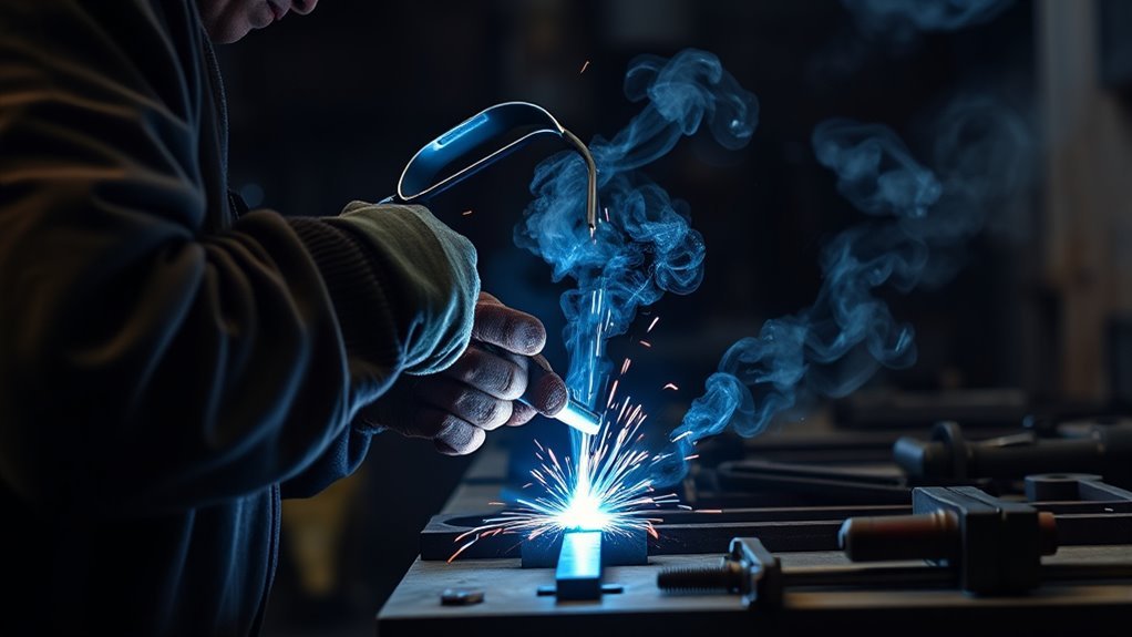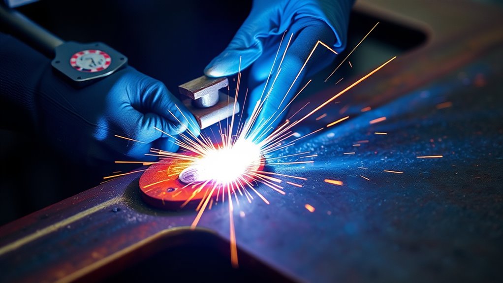
A weld pool, also called a weld puddle, is the molten metal that forms beneath a welding arc, flame, or other fusion-welding heat source. Learning to read its width, edges, fluidity, and movement helps you control fusion, bead shape, penetration, and defect risk in TIG, MIG/MAG, and SMAW welding.
Quick Answer
A weld pool is the molten metal present while a fusion weld is being made, before that metal solidifies into the finished weld. You control it through current, voltage, arc length, travel speed, electrode or torch angle, filler addition, joint fit-up, welding position, and shielding.
Key Takeaways
- A weld pool is molten metal; the weld bead is the metal after it cools and solidifies.
- A stable pool has a consistent width and wets both sides of the joint without sagging, racing ahead, or burning through.
- Current, voltage, travel speed, arc length, filler rate, shielding, material, joint design, and position all change pool behavior.
- Travel speed has an operating window: too fast can reduce fusion, while too slow can create an oversized pool and may also cause shallow fusion or cold lap.
- Pool appearance is a live process clue, not proof of penetration or structural quality.
Warning: Welding exposes you to hot metal, ultraviolet and infrared radiation, electrical shock, fire hazards, and metal fumes. Use a properly selected welding helmet, safety glasses, gloves, flame-resistant clothing, safe work practices, and effective ventilation. Do not weld coated metal, sealed containers, or in confined spaces unless you have the training, permits, ventilation, and respiratory controls the job requires. Review OSHA welding hazard guidance before working.
What Is a Weld Pool?
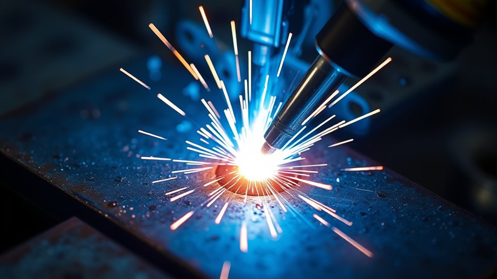
A weld pool is the localized area of molten base metal and, when used, filler metal that exists while a fusion weld is being made. The terms weld pool and weld puddle are commonly used for the same thing. After the pool cools and solidifies, it becomes weld metal. This definition matches the terminology used in Miller’s welding terms guide.
The pool lets the joint faces melt together. Its size, shape, flow, and solidification pattern affect bead profile, sidewall tie-in, depth of fusion, distortion, and the chance of defects.
The pool is not the same as the finished weld bead or the heat-affected zone. The bead is the solidified weld metal. The heat-affected zone is base metal that did not melt but had its properties changed by welding heat.
The pool gives you live feedback about the process, but the cooled weld and the required inspection determine whether the joint is acceptable.
Weld pools form in fusion processes such as TIG, MIG/MAG, flux-cored arc welding, SMAW, oxy-fuel welding, laser welding, and plasma arc welding. Solid-state processes join material without creating a conventional molten pool. If you are comparing wire processes, understanding flux-cored wire and its limitations can help you avoid confusing FCAW with standard gas-shielded MIG/MAG.
How Weld Pool Formation Works
A concentrated heat source raises a small area of the joint above the metal’s melting range. The base metal begins to melt, and filler metal may enter the liquid zone from a wire, rod, or coated electrode.
As the heat source moves, the front of the pool melts new base metal. The liquid metal spreads across, or wets, the joint faces. Behind the arc, the pool loses heat and solidifies into the bead. The rate and direction of this heat flow affect pool shape, cooling rate, distortion, and the weld’s final structure.
Full fusion requires the arc or heat source to act on the joint faces rather than only on previously deposited liquid metal. This is why both very fast and very slow travel can cause problems. Fast travel may not give the joint enough energy. Excessively slow travel can let the arc ride on a large puddle, producing a wide deposit with poor tie-in or shallow fusion.
In wire welding, voltage, wire feed speed, contact-tip-to-work distance, travel angle, and travel speed interact. A wire speed and voltage chart can give you a starting point, but the machine manual, filler-metal data, joint design, position, and test weld still control the final setup.
Note: Plasma cutting also uses concentrated arc heat, but its goal is to melt and eject metal rather than carry a controlled pool along a joint. A plasma cutting beginner’s guide can help clarify that difference.
What a Good Weld Pool Looks Like
A good weld pool does not have one universal size or shape. The right appearance depends on the process, joint, material, position, filler metal, and approved procedure. In general, look for these signs:
- Consistent width: The pool does not repeatedly swell and shrink as you move.
- Even wetting: Both joint edges melt and blend into the pool without a sharp unfused line.
- Controlled leading edge: The front of the pool stays under or just behind the heat source instead of racing ahead.
- Stable fluidity: The metal flows without violent turbulence, excessive sagging, or sudden collapse.
- Predictable solidification: The trailing edge freezes at a steady rate and leaves a uniform bead profile.
Do not judge quality by shine, ripple pattern, or brightness alone. Helmet shade, process, alloy, surface condition, and viewing angle all change what you see. Visual pool cues help you adjust technique, but they cannot confirm internal fusion, weld size, or code compliance by themselves.
Weld Pool Behavior in TIG Welding
In TIG welding, or gas tungsten arc welding, the nonconsumable tungsten electrode creates the arc while filler metal is added separately when needed. This separation gives you direct control over arc heat, pool movement, and filler timing.
- A short, steady arc concentrates the heat and usually makes the pool easier to control.
- More current generally increases the available heat and can enlarge the pool, but the result also depends on travel speed, joint design, polarity, and material.
- Argon or another specified inert shielding gas protects the hot tungsten and molten metal from the atmosphere.
- Consistent torch angle, travel speed, and filler placement support even bead shape.
Miller’s TIG technique guide recommends keeping the arc short and controlled while maintaining shielding coverage. Follow your machine and consumable instructions rather than treating one arc length or amperage rule as universal.
Filler chemistry and cleanliness also matter. For example, stainless steel TIG filler rod selection must match the base metal and service requirements. Keep the filler tip within the shielding envelope and avoid touching the tungsten to the pool.
Pro Tip: Watch the leading edge and both toes of the pool. If one side does not wet in, correct your work angle, arc position, fit-up, or heat before adding more filler.
Weld Pool Behavior in MIG/MAG Welding
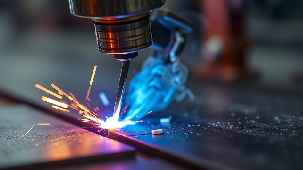
In gas metal arc welding, a continuously fed wire acts as both electrode and filler metal. The arc melts the wire and the base metal to form the pool. The main controls are voltage, wire feed speed, travel speed, gun angle, contact-tip-to-work distance, transfer mode, and shielding gas.
MIG technically refers to an inert shielding gas, while MAG uses an active gas or active-gas blend. In North American shop language, “MIG” is also widely used as a general label for GMAW, including common argon/carbon-dioxide blends.
On typical constant-voltage equipment, wire feed speed strongly affects welding current and deposition rate, while voltage affects arc length and bead profile. Miller’s MIG parameter guide shows that settings must be evaluated together and fine-tuned from the bead and arc behavior.
Shielding gas protects the molten zone from the atmosphere and also changes arc characteristics and bead shape. Use the gas and flow range specified for the base metal, wire, transfer mode, and machine. Excess flow is not always better because turbulence can pull air into the shielding envelope.
A MIG welding machine should be set from its door chart or manual first. Then make a test weld on matching scrap. When welding stainless steel, the correct shielding gas and filler combination depends on the alloy and transfer mode.
In MIG/MAG welding, voltage, wire feed speed, travel speed, stickout, and gas work as a system. Changing one variable can change several pool behaviors at once.
Coatings and contamination can make the pool unstable and create hazardous fumes. Review process-specific precautions before welding galvanized steel, and remove coatings only with safe methods that do not create a new exposure.
Weld Pool Behavior in SMAW
In shielded metal arc welding, or SMAW, the arc melts the coated electrode core and the base metal. The flux coating produces shielding and forms slag over the hot bead. You control the pool through current, arc length, electrode angle, travel speed, electrode type, polarity, and manipulation.
- Low current can cause a sticking or unstable arc and poor fusion.
- Excessive current can make the pool too fluid and increase spatter or undercut risk.
- An arc that is too long can increase spatter, undercut, and porosity risk.
- Travel speed should keep the arc working near the leading part of the pool.
Miller’s stick welding technique guide warns that traveling too slowly can direct heat into the puddle instead of the base metal, leading to a wide bead, shallow penetration, or cold lap.
Gravity becomes more important in vertical and overhead work. Use an electrode approved for the position, reduce pool size when needed, and follow the procedure for uphill, downhill, weave, or stringer technique. Do not assume a method that works flat is acceptable for a structural vertical or overhead joint.
Clean the joint as required for the electrode and application. Rust, paint, oil, moisture, and poor storage can contribute to gas entrapment and slag problems. This guide to porosity in arc welding explains common contamination and shielding causes.
How to Control Weld Pool Shape and Stability
Weld pool control comes from balancing the process variables rather than chasing one setting. Start with the welding procedure, machine chart, electrode package, or filler-metal data. Then change one variable at a time on matching scrap.
Products Worth Considering

【Stable Arc with IGBT Technology】Powered by a high-performance IGBT inverter system, this ARC welder delivers a stable arc, fast ignition, reduced spatter, and consistent penetration. Whether you're a professional welder or a beginner, achieving cleaner and stronger welds becomes easier than ever

3-IN-1 PULSE STICK WELDER: The ARC205P PRO combines Pulse MMA, Standard MMA, and Lift TIG in one versatile machine. Pulse mode reduces heat input, spatter, distortion, and electrode consumption, making it ideal for thinner steel and precision repairs. Standard MMA delivers powerful performance for structural steel, fabrication, and maintenance, while Lift TIG provides cleaner, more precise welds for stainless steel and detailed metalwork. (Lift TIG torch sold separately.)
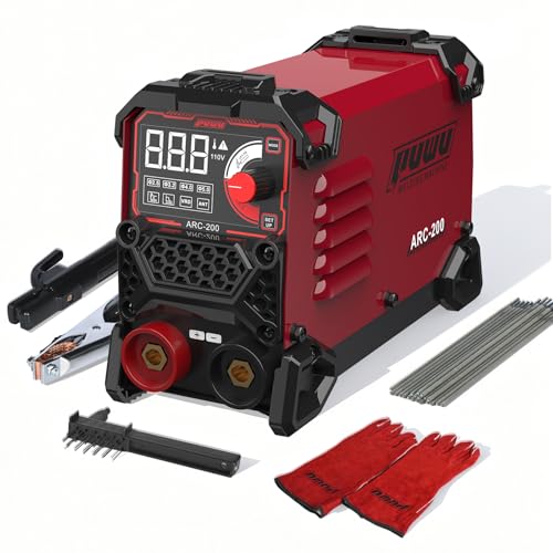
EASY TO USE: PUWU ARC-200 expertly handles Stick and Lift TIG welding.Welder machine 110V Adjustable Current: 20-200A. Comes with 20 welding rods, can weld metal materials with 0.06-0.2 inch thickness, such as cast iron, mild steel, etc. Ideal for home repairs and DIY projects. The welding machine 110V great for AWS E6013, E6011, E6010 1/16"-1/8"(1.6mm-3.2mm) welding rods can weld all kinds of metal.A perfect choice for beginners.Circuit breakers are recommended 40A to 50A.
Heat Input Control
- Use the specified current range for the electrode, wire, tungsten, material thickness, joint, and position.
- Increase current in small steps when the arc is unstable or the joint faces are not melting, provided the procedure allows it.
- Reduce current when the pool is excessively fluid, undercut develops, or thin metal begins to sag or burn through.
- Do not treat voltage as a simple “heat knob.” In GMAW, voltage also changes arc length and bead profile.
- On critical work, stay within the qualified welding procedure instead of tuning by appearance alone.
More available heat often enlarges the molten zone, but penetration is not controlled by heat input alone. Arc force, polarity, transfer mode, gas, joint geometry, travel speed, and where the arc acts on the pool all matter.
Travel Speed Balance
Travel speed changes the time the heat source acts on each part of the joint. Moving too fast can leave a narrow bead, poor toe tie-in, underfill, or incomplete fusion. Moving too slowly can create a wide pool, excessive buildup, burn-through on thin metal, or poor fusion when the arc rides on top of the puddle.
Use a speed that keeps the pool at a repeatable size and keeps the arc focused where new base metal must melt. For SMAW, a useful visual cue is keeping the arc near the leading portion of the pool. For TIG and GMAW, keep the leading edge moving steadily without outrunning the shielding envelope.
Arc Length, Stickout, and Angle
A longer arc usually spreads heat and reduces control. It may also increase oxidation, spatter, or undercut, depending on the process. Keep the arc length within the process and consumable guidance.
In GMAW, excessive contact-tip-to-work distance can lower current on many constant-voltage setups and make the arc less stable. In TIG, a long arc broadens the heat pattern and can reduce shielding coverage. In SMAW, arc length changes as the electrode burns, so you must feed the rod toward the joint to hold a steady gap.
Work angle directs heat between the joint faces. Travel angle influences arc force, visibility, shielding, and bead shape. Keep both angles consistent and adjust for unequal thickness so the thicker member receives enough heat without overheating the thin side.
Filler Metal and Shielding
Too much filler can chill or overfill the pool. Too little can leave underfill or make it harder to bridge the joint. Add filler at a steady rate that matches travel speed and joint volume.
Gas-shielded processes need clean, undisturbed coverage. Check for leaks, blocked nozzles, drafts, wrong gas, excessive or inadequate flow, and poor torch angle. For flux-shielded processes, use dry, correctly stored consumables and remove slag as required between passes.
Material, Joint, and Position
Aluminum, carbon steel, stainless steel, and copper alloys move heat differently. Thickness, backing, joint gap, bevel, tack spacing, and part mass also change how quickly the pool forms and freezes. Use matching scrap whenever possible.
Gravity pulls the pool downward in vertical and overhead positions. A smaller, faster-freezing pool is often easier to hold, but the exact settings and technique must match the electrode classification and procedure.
How to Read the Weld Pool While Welding
- Establish the pool: Hold the arc on the joint until both required faces begin to melt. Do not race forward before the pool forms.
- Watch the edges: Confirm that the liquid metal wets both toes. A sharp line at one edge can indicate poor angle, poor arc placement, contamination, or low energy.
- Track the leading edge: Keep the heat source working on fresh base metal, not only on the center of an oversized puddle.
- Hold a steady width: Keep your travel speed, arc length, and filler rhythm consistent so the pool does not surge.
- Watch the trailing edge: The pool should freeze in a controlled pattern without craters, sudden collapse, or metal running out of the joint.
- Inspect after cooling: Check bead size, toe tie-in, undercut, porosity, crater fill, distortion, and any inspection requirements in the welding procedure.
Note: A smooth-looking pool cannot prove root penetration or internal soundness. Critical welds may require procedure qualification, destructive testing, or nondestructive examination by qualified personnel.
Common Weld Pool Defects and What They Mean
Weld defects often appear after the pool solidifies, but many begin with poor heat control, shielding, fit-up, or technique. Use the finished bead, process behavior, and procedure requirements together when troubleshooting.
| What you see | Likely causes | First checks |
| Porosity or pinholes | Oil, rust, paint, moisture, gas leaks, drafts, wrong gas, contaminated filler, or excessive gas turbulence | Clean and dry the joint, inspect gas delivery, block drafts safely, and verify consumables |
| Lack of fusion or cold lap | Low current, poor arc placement, wrong angle, fast travel, or travel so slow that the arc rides on the puddle | Aim at the joint faces, correct angle and speed, and adjust within the approved range |
| Undercut | Excess current or voltage, long arc, fast travel, poor angle, or failure to pause at the toes | Shorten and stabilize the arc, correct angle, and reduce the setting if allowed |
| Burn-through | Too much current, slow travel, wide gap, poor fit-up, or too much dwell on thin metal | Reduce heat, improve fit-up, shorten dwell, or use backing when the procedure permits |
| Excess spatter or turbulent pool | Mismatched voltage and wire feed, long arc, excessive stickout, contamination, poor polarity, or unstable shielding | Verify polarity and consumables, clean the work, restore recommended stickout, and retune the arc |
| Sagging or metal running out | Pool too large for the position, excessive heat, wrong electrode, or poor manipulation | Use position-rated consumables, reduce pool size, and follow the approved vertical or overhead technique |
Make one controlled adjustment at a time, then repeat the test weld. If the work is structural, pressure-retaining, safety-critical, or code-regulated, stop and use the applicable welding procedure and inspection requirements rather than relying on trial and error.
Products Worth Considering

【Upgrade Technology】The soldering iron is upgraded 80W High Power, and can make the soldering iron quickly heat up within 20 seconds; This soldering iron can accurately adjust the temperature and a flexible temperature range of 180℃-480℃/ 356°F-896°F.

🔧 Upgraded Soldering Kit - The 90W 110V soldering iron uses a high-power advanced ceramic heating core, which heats up quickly within 20 seconds, allowing you to work faster. And our digital soldering iron has a non-slip silicone sheath, which is soft and comfortable to handle, allowing you to avoid scalding during operation

【UPGRADE SOLDERING IRON】The 100W soldering iron uses a high-power, advanced plug-in ceramic heating core that heats up quickly in 15 seconds, allowing you to work faster. Its temperature calibration function also ensures accurate and reliable temperature control. The pen-style iron is also portable and easy to carry.
Frequently Asked Questions
Is a weld pool the same as a weld puddle?
Yes. Weld pool and weld puddle are commonly used as interchangeable terms for the molten metal present while a fusion weld is being made.
What does a good weld pool look like?
A good pool has a consistent size, wets the required joint faces, and moves without violent turbulence, sagging, or sudden collapse. The correct size and shape depend on the process, material, joint, and welding position.
Why is my weld pool too large?
Common causes include excessive current, high voltage for the process, slow travel, a long arc, too much dwell, or a joint gap that is too wide. Correct the cause in small steps and stay within the machine, consumable, or procedure limits.
Why is my weld pool too small?
The current may be too low, travel may be too fast, the arc may be missing the joint root, or the part may be drawing heat away faster than expected. Check fit-up, arc placement, polarity, consumables, and starting settings before raising current.
How does travel speed affect the weld pool?
Fast travel usually makes the pool smaller and can reduce toe tie-in or fusion. Slow travel usually enlarges the pool, but going too slowly can cause excessive buildup, burn-through on thin metal, or shallow fusion when the arc rides on the puddle.
Can poor weld pool control cause porosity?
It can contribute, but porosity is usually tied to gas entrapment from contamination, moisture, poor shielding, drafts, leaks, wrong gas, or unsuitable consumables. Clean the joint and verify shielding before changing heat alone.
Can you tell penetration by watching the weld pool?
You can see clues such as sidewall wetting and pool response, but you cannot prove root penetration or internal soundness from the top surface alone. Critical welds require the inspection or testing specified by the applicable procedure or code.
Why is a vertical or overhead weld pool harder to control?
Gravity pulls molten metal out of the joint. The process may need a smaller pool, a position-rated electrode or transfer mode, adjusted current, and a specific travel or manipulation technique.
Conclusion
Understanding the weld pool helps you make better choices while the weld is still forming. Watch the pool’s width, leading edge, toes, fluidity, and solidification pattern, then adjust current, voltage, arc length, travel speed, angle, filler, or shielding one variable at a time.
Do not confuse a smooth-looking pool with a proven sound weld. Use the correct procedure, inspect the cooled bead, and apply required testing on critical work. Better pool control improves consistency, but safe setup, clean material, correct consumables, and qualified inspection complete the job.
Sources
- Miller Electric: Understanding Common Welding Terms — weld pool, weld toe, penetration, porosity, and shielding terminology.
- Miller Electric: TIG Welding Tips — TIG arc length, torch angle, shielding, and puddle control.
- Miller Electric: MIG Welding Parameters — wire feed speed, voltage, travel speed, bead appearance, and shielding faults.
- Miller Electric: Five Steps to Improving Stick Welding Technique — current, arc length, travel angle, speed, and puddle position.
- Occupational Safety and Health Administration: Welding Hazards and Solutions — radiation, burns, electrical, fume, and PPE hazards.
- NIOSH: Welding Fumes and Manganese — welding-fume composition, exposure concerns, and confined-space risk.