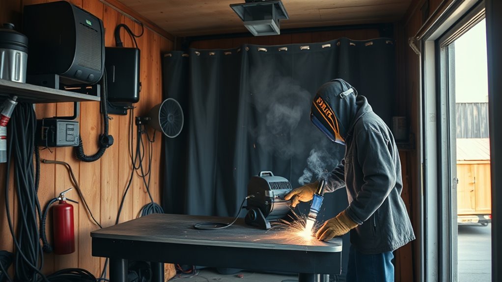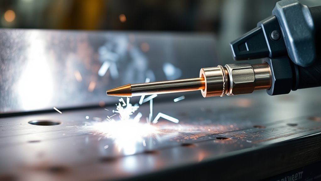
Stick-out in MIG welding is a small distance with a large effect. A change of only a few tenths of an inch can alter amperage, arc stability, penetration, spatter, and bead shape even when the machine settings stay the same. The correct target depends on the transfer mode, wire, contact-tip position, joint, and welding procedure.
Quick Answer
MIG stick-out is the unmelted wire between the gun and the arc. For short-circuit solid-wire MIG, start near a 3/8-inch contact-tip-to-work distance. Pulsed or spray transfer often uses about 3/4 inch. Keep the distance steady, then follow the welder chart, wire data sheet, or approved welding procedure.
Key Takeaways
- In strict welding terminology, electrode extension, stickout, and contact-tip-to-work distance measure from different points.
- A shorter electrode extension generally raises amperage in constant-voltage MIG; a longer extension generally lowers it.
- Short-circuit MIG commonly uses a shorter distance than pulsed, spray, or many flux-cored applications.
- Do not use stick-out alone to correct a bad weld. Check voltage, wire feed speed, travel speed, polarity, gas, and technique.
- For code work or critical joints, the welding procedure specification and consumable manufacturer instructions take priority over general rules.
At a Glance
| Time Required | 5–10 minutes to check the setup and run a test bead |
| Difficulty | Beginner |
| Tools Needed | MIG welder, side cutters, ruler or marked gauge, scrap coupon, and welding PPE |
| Cost | No added cost beyond normal wire, gas, scrap metal, and PPE |
What’s in This Article
- What Is Stick-Out in MIG Welding?
- Stickout, Electrode Extension, and CTWD
- How Stick-Out Affects Amperage
- Why Stick-Out Changes Penetration
- Recommended MIG Stick-Out Ranges
- How to Set and Check Stick-Out
- How Gun Angle Affects Stick-Out
- Common MIG Stick-Out Mistakes
- Troubleshooting Stick-Out Problems
- Frequently Asked Questions
- Conclusion
Warning: MIG welding exposes you to arc radiation, hot metal, electric shock, fire, fumes, and shielding gases. Wear suitable welding PPE, remove fire hazards, keep your head out of the fume plume, and use effective ventilation or local exhaust. Never weld in a confined space without the required controls and training. See OSHA welding, cutting, and brazing guidance.
What Is Stick-Out in MIG Welding?

Stick-out describes the unmelted wire between part of the welding gun and the point where the wire melts into the arc. Welders often use the word loosely, which is why two people can quote different distances while describing the same setup.
According to Miller’s explanation of welding terminology, strict usage separates the following measurements:
- Electrode extension: contact tip to the wire melt-off point.
- Stickout: nozzle end to the wire melt-off point.
- Contact-tip-to-work distance (CTWD): contact tip to the workpiece before the arc starts; during welding, it includes electrode extension plus arc length.
The most useful habit is not chasing one universal number. It is using the correct reference point and holding that distance steady for the selected process.
Many owner manuals and shop conversations call electrode extension or CTWD “stickout.” That wording is common, but the reference point still matters. A recessed contact tip can make nozzle-to-wire stickout look short while the electrical extension is much longer.
For beginners using short-circuit MIG on mild steel, Miller recommends about 3/8 inch from the contact tube to the unmelted wire end, excluding the arc. Use that as a starting point, not a replacement for the chart inside the welder door or the approved procedure.
For related wire-handling practice, this guide to flux-core welding tips for beginners explains why consistent gun position matters with tubular wire as well.
What’s the Difference Between Stickout, Electrode Extension, and CTWD?
The three measurements only match in special setups. If the contact tip is flush with the nozzle, nozzle-based stickout and contact-tip-based electrode extension start from nearly the same place. If the tip is recessed or protruding, the values differ.
| Term | Measured From | Measured To | Why It Matters |
|---|---|---|---|
| Electrode extension | End of contact tip | Wire melt-off point | Directly changes resistance and amperage in constant-voltage GMAW |
| Stickout | End of nozzle | Wire melt-off point | Useful only when nozzle and tip position are known |
| CTWD | End of contact tip | Workpiece surface | Easy to set before welding and common in procedures and robot programming |
| Arc length | Wire melt-off point | Weld pool or workpiece | Closely related to voltage; it is not the same as stick-out |
Use precise terms when following a welding procedure specification, setting a robot, or troubleshooting a production weld. A measurement from the nozzle cannot be copied accurately unless the contact-tip recess is also known.
Note: Stick-out is not a substitute for joint design or weld size. For load-carrying work, use the required procedure and verify items such as fillet weld sizing separately.
How Stick-Out Affects Amperage
Solid MIG wire has electrical resistance. In a constant-voltage GMAW system, increasing electrode extension adds resistance and increases resistance heating in the wire before it reaches the arc. The power source responds by operating at lower current. Shortening the extension usually raises current.
This is why the same voltage and wire feed speed can feel different when your hand moves closer to or farther from the joint. The machine settings did not change, but the electrical part of the setup did.
| Change | Typical Current Response | Likely Result |
|---|---|---|
| Shorter electrode extension | Higher amperage | Hotter, stiffer arc; more burn-through or contact-tip damage risk if too short |
| Correct, steady extension | Stable operating range | More repeatable sound, bead profile, and penetration |
| Longer electrode extension | Lower amperage | Softer or less stable arc; poor penetration or fusion if excessive |
In one Miller spray-transfer example, changing CTWD from 5/8 inch to 1 inch shifted current from about 282 amps to 213 amps. The exact numbers are setup-specific, but the example shows why distance control matters.
Wire feed speed remains the main amperage control in conventional constant-voltage MIG, while voltage mainly affects arc length and bead profile. Set the machine correctly first, then hold CTWD steady. This MIG wire speed and voltage guide explains the relationship in more detail.
Why Stick-Out Changes Penetration
Penetration changes because electrode extension affects current and where electrical heating occurs. With a shorter extension, current usually rises and more arc energy reaches the joint. With an excessive extension, more resistance heating occurs in the wire, current falls, and penetration can decrease.
Shorter Stick-Out: Higher Current and More Heat Risk
A controlled, shorter extension can help maintain fusion in short-circuit MIG. Too short is not better, however. It can raise current beyond the intended range, make the gun difficult to hold steady, overheat or damage the contact tip, and increase burn-through risk on thin sheet.
- Use the recommended distance for the transfer mode.
- Keep the contact tip from touching the work or puddle.
- Do not shorten CTWD to compensate for settings that are too cold.
- Test on scrap of the same material and thickness before welding the part.
Warning: An extremely short CTWD can overheat the puddle, damage the contact tip, or cause burn-through. Release the trigger before repositioning the gun, and keep the energized wire away from your body and grounded surfaces.
Longer Stick-Out: Lower Current and Fusion Risk
An excessive extension often produces lower current, a less forceful arc, more spatter, and reduced root or sidewall fusion. The bead may still look wide or smooth on top, so appearance alone does not prove adequate penetration.
Longer CTWD may be correct for pulsed, spray, metal-cored, or flux-cored procedures. The problem is not “long” by itself; it is using a distance that does not match the selected wire, transfer mode, nozzle setup, and procedure.
Polarity also affects arc behavior and penetration. Confirm the machine is connected for the wire being used; this guide explains why flux-core gas requirements and polarity vary by consumable.
How Long Should MIG Stick-Out Be?
There is no single correct stick-out for every MIG weld. Use the table below as a starting point, then confirm the welder chart, owner manual, wire data sheet, or welding procedure specification.
| Process or Transfer Mode | Practical Starting Point | Important Notes |
|---|---|---|
| Solid-wire short-circuit MIG | About 3/8 inch CTWD; many manuals allow roughly 1/4–1/2 inch | Common for thin steel and out-of-position work; contact tip is often flush with or slightly beyond the nozzle |
| Solid-wire spray or pulsed spray | About 3/4 inch CTWD; many manuals show roughly 1/2–3/4 inch | The contact tip is often recessed; follow the programmed process or manufacturer recommendation |
| Self-shielded flux-cored wire | Around 3/4 inch is common for general-purpose wire | Wire-specific values vary; use the consumable data sheet and drag technique when required |
| Gas-shielded flux-cored or metal-cored | Use the wire manufacturer’s CTWD | Industrial wires may require values outside hobby MIG ranges |
Miller lists about 3/8 inch for short-circuit transfer and about 3/4 inch for pulsed or spray transfer. Its flux-cored mild-steel guide gives approximately 3/4 inch as a general FCAW starting point.
Note: The visible wire beyond the nozzle is not enough information when the contact tip is recessed. Measure from the contact tip when a manual or procedure specifies CTWD or electrode extension.
For machine-specific examples, compare the values in this flux-core and MIG settings chart with the chart supplied by your welder and wire manufacturer.
How to Set and Check Stick-Out Consistently
You do not need a special tool for basic manual welding. A ruler, a marked scrap gauge, or a consistent visual reference is enough to establish the starting distance.
1. Confirm the Process and Transfer Mode
Identify the wire type, diameter, shielding gas, polarity, and transfer mode. A 3/8-inch short-circuit setup and a 3/4-inch pulsed setup can both be correct, but not for the same procedure.
2. Check the Contact-Tip Position
Look into the nozzle and note whether the contact tip is flush, protruding, or recessed. Remove spatter that blocks gas flow, and replace a worn or damaged tip before measuring.
3. Trim and Measure the Wire
With the trigger released, trim the wire to a repeatable starting length. Position the gun at the intended work and travel angles, then measure contact-tip-to-work distance if that is the value specified.
4. Brace the Gun and Run a Test Bead
Use both hands when possible. Brace a wrist, forearm, or elbow without placing skin near hot metal. Run a bead on clean scrap that matches the joint material and thickness.
5. Read the Arc and Bead
Watch the leading edge of the puddle. Listen for a steady arc appropriate to the transfer mode. Check for spatter, bead shape, undercut, overlap, burn-through, and visible lack of fusion.
6. Change One Variable at a Time
If the result is poor, return CTWD to the recommended value before changing voltage or wire feed speed. Then adjust one setting at a time and record the result.
Pro Tip: Cut a small notch in a nonconductive gauge at the target CTWD. Use it before each practice bead so your distance starts the same every time.
How Gun Angle Affects Stick-Out

Gun angle does not change the wire length by itself, but it changes the path and spacing between the tip, arc, joint, and workpiece. If you rotate the gun while keeping your hand in the same place, the effective CTWD at the arc can drift.
For many MIG welds, a travel angle of about 5–15 degrees is a useful starting range. Miller warns that travel angles beyond roughly 20–25 degrees can increase spatter, reduce penetration, and destabilize the arc.
- Butt joint: center the work angle between both plates.
- T-joint: begin near a 45-degree work angle, then bias slightly toward the thicker member if the procedure permits.
- Lap joint: aim the wire into the joint root and direct enough heat into the lower or thicker piece.
- Vertical or overhead: keep the puddle small and follow the process-specific procedure; do not rely on extra stick-out as the main heat-control method.
When welding coated material, clean the joint and control fume exposure. This guide to MIG welding galvanized steel covers the extra concerns created by zinc coatings.
Pro Tip: Watch the contact tip, wire, and leading puddle edge as one picture. If the nozzle drifts but the wire-to-puddle relationship stays stable, avoid making a sudden correction that changes CTWD.
Common MIG Stick-Out Mistakes
Using One Number for Every Process
A range that works for short-circuit steel may be wrong for pulsed aluminum, spray transfer, metal-cored wire, or self-shielded flux core. Start with process-specific guidance.
Measuring From the Wrong Point
If a procedure specifies CTWD, measure from the contact tip, not the nozzle. A recessed tip can hide a large difference.
Holding the Gun Too Far Away
Excessive CTWD can lower current, reduce penetration, destabilize shielding coverage, and increase spatter. It can also make the wire wander before reaching the puddle.
Holding the Gun Too Close
Too little distance can raise current, overheat the puddle, promote burn-through, and damage the contact tip. It also reduces your view of the joint.
Changing Stick-Out to Mask Other Problems
A cold, ropey, porous, or spattery weld may come from incorrect voltage, wire feed speed, travel speed, polarity, shielding gas, dirty metal, worn consumables, or poor work-lead contact. Restore the recommended CTWD before troubleshooting other variables.
Ignoring Nozzle and Tip Condition
Spatter inside the nozzle can disturb gas flow. A worn contact tip can let the wire wander and make extension appear inconsistent even when your hand position is steady.
For broader setup and PPE reminders, review this welding and plasma-cutting safety checklist; apply the instructions in your MIG welder’s own manual first.
Troubleshooting Stick-Out Problems
| Symptom | Possible Distance Problem | What to Check Next |
|---|---|---|
| Arc sounds irregular and wire feels like it is pushing the gun back | CTWD may be too long or changing | Return to the recommended distance; then check voltage and wire feed speed |
| Burn-through or overheated contact tip | CTWD may be too short | Check heat settings, travel speed, material thickness, and tip condition |
| Cold-looking bead or poor root fusion | CTWD may be excessive | Confirm polarity, voltage, wire feed speed, travel speed, joint preparation, and work angle |
| Heavy spatter | Distance may be wrong or inconsistent | Check transfer mode, gas type and flow, polarity, clean metal, and consumables |
| Porosity | Nozzle-to-work distance may be too large for reliable coverage | Check drafts, leaks, blocked nozzle, flow rate, contamination, and gas supply |
| Bead width changes during one pass | CTWD or gun angle may be drifting | Brace the gun, shorten the practice bead, and keep travel speed steady |
Do not judge weld strength from appearance alone. Critical welds may require inspection or testing under the governing code or procedure. For additional symptom checks, see these MIG welding problems and solutions.
Note: If the bead changes while the machine settings remain unchanged, check CTWD, gun angle, travel speed, wire feeding, and work-lead contact before turning the controls.
Products Worth Considering

Package list: 30 pieces of 0.030 inch mig welder tips.

1. Package Includes 30 Premium Quality .023” (Ø0.6mm)welding Tips.
1. Package Includes 30 Premium Quality .035” (Ø0.9mm)welding Tips.
Frequently Asked Questions
What happens when MIG stickout is increased?
Increasing electrode extension in constant-voltage MIG usually increases resistance and lowers amperage. If the distance becomes excessive, penetration and arc stability can fall while spatter may increase. A longer distance can still be correct for pulsed, spray, or certain cored-wire procedures.
Is stick-out the same as arc length?
No. Arc length is the gap from the wire melt-off point to the weld pool. Electrode extension is the unmelted wire from the contact tip to the melt-off point. CTWD includes both electrode extension and arc length during welding.
What stick-out should you use for flux-core welding?
About 3/4 inch is a common starting point for general-purpose self-shielded flux-cored wire, but cored wires vary widely. Use the wire manufacturer’s data sheet, the welder chart, and the approved procedure for the exact CTWD and polarity.
Can too short a stick-out cause problems?
Yes. Too little electrode extension can raise amperage, overheat the puddle, damage the contact tip, reduce visibility, and increase burn-through risk on thin metal.
Why does stick-out change spatter?
Distance changes affect current, wire heating, and arc behavior. An incorrect or drifting CTWD can make metal transfer less stable. Spatter can also come from poor voltage or wire feed settings, wrong polarity, unsuitable gas, contamination, or worn consumables.
Where should I measure MIG stick-out from?
First check the wording in the manual or procedure. Electrode extension is measured from the contact tip to melt-off. Strict stickout is measured from the nozzle to melt-off. CTWD is measured from the contact tip to the workpiece.
Can I make a cold weld hotter by shortening stick-out?
A shorter electrode extension may raise current, but it is not the right way to hide incorrect settings. Return to the recommended CTWD and correct wire feed speed, voltage, travel speed, polarity, gas, and joint preparation.
Conclusion
Consistent MIG stick-out helps keep amperage, penetration, arc sound, and bead shape repeatable. The useful number depends on what you are welding: short-circuit solid-wire MIG commonly starts near 3/8 inch CTWD, while pulsed, spray, and many flux-cored procedures use a longer distance.
Measure from the reference point named in the manual or procedure, check whether the contact tip is recessed, and hold both gun angle and travel speed steady. When a bead changes, restore the correct CTWD before changing the machine controls.
For structural, pressure, vehicle-safety, or other critical work, follow the qualified welding procedure and required inspection rules rather than relying on a general technique guide.
Sources
- Miller Electric: Stickout, Electrode Extension, and CTWD — definitions and the effect of extension on amperage.
- Miller Electric: MIG Welding Basics for Mild Steel — short-circuit stickout and gun-angle guidance.
- Miller Electric: Reduce Weld Rework — CTWD guidance for short-circuit versus pulsed and spray transfer.
- Miller Electric: Flux-Cored Welding Basics — common flux-cored stickout and gun technique.
- Lincoln Electric: Variables That Affect Weld Penetration — the relationship between CTWD, resistance, current, and penetration.
- OSHA: Welding, Cutting, and Brazing — workplace standards, ventilation, fume, fire, and PPE resources.