
Travel speed can make a weld look acceptable while hiding poor fusion at the toes or root. Move too fast and the arc can outrun the puddle. Move too slowly and excess weld metal can shield the base metal from the arc, widen the bead, or burn through thin stock. The correct pace is the one that works with the approved settings, joint, position, and process.
This guide explains what welding travel speed controls, how to measure it, how to read the puddle, and how to correct common MIG, stick, TIG, and flux-cored welding problems.
Quick Answer
Travel speed in welding is the rate at which the torch, gun, or electrode moves along the joint, usually measured in inches per minute or millimeters per minute. It changes heat input per unit length, weld size, penetration, and toe tie-in. There is no universal correct speed; use the procedure, puddle, and test results.
Key Takeaways
- Travel speed must be matched to amperage, voltage, wire feed speed, electrode, joint design, position, and material.
- Both excessively fast and excessively slow travel can reduce penetration or fusion.
- A good bead has the required size, smooth toe tie-in, and a stable profile, but appearance alone does not prove weld soundness.
- Measure travel speed by timing a known weld length instead of relying only on feel.
- For structural, pressure, vehicle-safety, or code work, follow the qualified welding procedure specification (WPS) and required inspection or testing.
At a Glance
| Time Required | About 20–30 minutes to prepare scrap, run three timed beads, and compare the results |
| Difficulty | Beginner to intermediate |
| Tools Needed | Welder, matching scrap coupons, filler wire or electrodes, PPE, clamps, cleaning tools, marker or chalk, ruler, and stopwatch |
| Cost | Usually limited to scrap and consumables when you already own the welding equipment |
What’s in This Article
- What Is Travel Speed in Welding?
- How Travel Speed Changes Penetration and Bead Shape
- How to Measure Welding Travel Speed
- How Travel Speed Works With Amperage, Voltage, and WFS
- MIG Welding Travel Speed: Signs You’re Off
- Stick Welding Travel Speed: What to Watch For
- TIG and Flux-Cored Travel Speed
- How Material Thickness Changes Travel Speed
- How Joints and Position Change Travel Speed
- How to Dial In Travel Speed on Scrap
- How to Read Bead Shape as You Weld
- Travel Speed Troubleshooting Chart
- Common Travel Speed Mistakes to Avoid
- Frequently Asked Questions
- Conclusion
- Sources
Warning: Welding exposes you to arc radiation, hot metal, sparks, fumes, gases, fire, and electric-shock hazards. Wear suitable eye, face, hand, body, and foot protection; remove or shield combustibles; keep fire-extinguishing equipment ready; and use ventilation that meets the material and work-area requirements. Never use oxygen as ventilation, and keep chlorinated-solvent vapors away from arc welding.
What Is Travel Speed in Welding?
Travel speed in welding is the rate at which the torch, gun, or electrode advances along the joint while the arc is on. Manual welders commonly describe it in inches per minute (IPM) or millimeters per minute (mm/min). Mechanized systems can hold and record the value more precisely.
Travel speed is one part of a complete welding procedure. It works with current, voltage, wire feed speed, arc length or contact-tip-to-work distance, electrode angle, filler-metal deposition, shielding, joint preparation, and welding position. Changing speed without considering those variables can create a bead that looks smooth but still has lack of penetration or fusion.
There Is No Universal Correct Travel Speed
A fixed recommendation such as “always weld at 10 to 12 IPM” is not reliable. The correct range changes with the process, transfer mode, electrode or wire, material, thickness, joint, position, machine settings, and required weld size. Start with the machine chart, consumable data sheet, or WPS, then verify the result on representative scrap.
For production or code work, travel speed may be a controlled procedure variable. Do not replace an approved range with a visual guess.
Travel speed is correct only when it produces the required weld size, fusion, profile, and test results with the rest of the procedure held within its allowed range.
How Travel Speed Changes Penetration and Bead Shape
At the same measured voltage and current, faster travel generally reduces electrical energy delivered per unit length. The bead usually becomes smaller and narrower. If the arc moves beyond the leading edge of the puddle, the weld may have poor toe tie-in, underfill, undercut, or insufficient penetration.
Slower travel increases energy per unit length, but it does not guarantee deeper penetration. Once the puddle becomes too large, the arc can spend more energy heating molten filler metal instead of the base metal. The result may be a wide, convex bead with overlap, cold lap, shallow penetration, or burn-through on thin material.
Penetration Depth Is Not Linear
When travel is excessively fast, reducing speed can give the arc more time to act on the joint and may improve penetration. Keep slowing, however, and the growing puddle can cushion the arc and reduce effective fusion. That is why both extremes can produce a weak weld.
Penetration also depends on amperage, polarity, process, shielding gas, electrode type, travel angle, work angle, arc length, and joint preparation. Travel speed should never be treated as the only penetration control.
Bead Width and Reinforcement
Travel speed strongly affects how much weld metal is deposited per unit length:
- Too fast: undersized or narrow bead, poor toe tie-in, possible undercut, and irregular ripples.
- Balanced: required bead size, smooth toes, stable profile, and a puddle that remains under the arc.
- Too slow: oversized or excessively convex bead, overlap or cold lap, excess heat, and possible burn-through.
The desired profile depends on the joint and procedure. A flat-looking bead is not automatically good, and a visible “stacked-dime” pattern is not proof of fusion.
Heat Input per Unit Length
A common traditional estimate is:
Heat input (kJ per unit length) = voltage × amperage × 60 ÷ travel speed ÷ 1,000
Use matching distance units for the result: IPM gives kJ/in, while mm/min gives kJ/mm. Some procedures apply an efficiency factor or use measured instantaneous energy instead of average voltage and current. Follow the calculation method required by the applicable code, WPS, or quality system. Lincoln Electric explains both the traditional and measured-energy approaches in its True Energy heat-input guide.
Pro Tip: When practicing, change only one variable at a time. If you change voltage, wire feed speed, angle, and travel speed together, the finished bead will not tell you which change helped.
How to Measure Welding Travel Speed
You can measure manual travel speed with a ruler, a marker, and a stopwatch. Mark a known distance on the coupon, time only the arc-on movement over that distance, and use one of these formulas:
- IPM = weld length in inches × 60 ÷ arc time in seconds
- mm/min = weld length in millimeters × 60 ÷ arc time in seconds
For example, a 6-inch bead completed in 30 seconds equals 12 IPM. Time several beads because starts, stops, and hand-position changes can distort a single measurement.
On a long weld, mark equal sections and record the time for each section. This shows whether you accelerate as the plate heats or slow down as your body position becomes less comfortable.
How Travel Speed Works With Amperage, Voltage, and WFS
Travel speed is often the final technique adjustment, but it cannot correct a badly chosen setup. In most constant-voltage MIG systems, wire feed speed (WFS) primarily controls welding current and deposition rate, while voltage strongly affects arc length and bead width. Travel speed then determines how much of that deposited metal and arc energy is placed in each inch or millimeter of joint.
Use the equipment chart, owner’s manual, consumable data, or WPS as the starting point. Then fine-tune in small steps:
- Set the correct process, polarity, wire or electrode, and shielding gas.
- Choose the starting voltage and WFS or amperage for the material and joint.
- Hold the required work angle, travel angle, arc length, and stickout or contact-tip-to-work distance.
- Adjust travel speed enough to keep the arc at the leading edge of a stable puddle and produce the required bead size.
- Recheck the weld after cooling and cleaning.
Higher WFS may require more travel speed to prevent excess deposit, but only after the arc and current are set correctly. Higher voltage does not automatically mean “move faster”; excessive voltage can make the arc turbulent, widen the bead, and promote undercut. Miller’s MIG parameter guide shows how bead symptoms can come from voltage, WFS, or travel speed.
Angle, Arc Length, and Stickout
Even a steady travel speed can fail if the arc points away from the joint or the electrode extension changes. Maintain the work and travel angles required for the joint. In MIG welding, inconsistent contact-tip-to-work distance changes current and shielding behavior. In stick welding, the comparable hand-controlled variable is arc length, not wire stickout.
Note: Shielding-gas flow for MIG or TIG and gas pressure for plasma cutting are different setup topics. Do not use plasma-cutter pressure guidance to set a welding gas flowmeter.
MIG Welding Travel Speed: Signs You’re Off
In MIG welding, watch the leading edge of the puddle rather than the bright center of the arc. The wire should feed into the correct part of the joint while the puddle wets into both toes.
Travel that is too fast often produces a narrow or convex bead with poor tie-in, insufficient penetration, underfill, or undercut. The puddle appears to fall behind the arc, and the bead may become irregular.
Travel that is too slow can create an excessively wide or convex bead with too much deposit. The large puddle may roll ahead of the arc, causing overlap, cold lap, or poor penetration. Thin stock may overheat or burn through.
A steady “sizzle” can be a useful clue during short-circuit MIG, but sound changes with transfer mode, gas, wire, and machine. Diagnose the weld from the puddle, bead, settings, and test results together—not sound alone.
Stick Welding Travel Speed: What to Watch For
For shielded metal arc welding (SMAW), establish a puddle of the required size and keep the arc near the leading portion of that puddle. Miller’s stick-welding technique guide warns that traveling too slowly can direct heat into the puddle instead of the base metal, creating cold lap or poor fusion.
Watch for these signs:
- Too fast: undersized bead, a crowned or pointed ripple pattern, underfill, undercut, and reduced penetration.
- Too slow: wide or heavily convex deposit, shallow penetration, slag entrapment risk, overlap, or cold lap.
- Balanced: the arc stays at the puddle’s leading edge, the bead reaches the required size, and slag follows without overtaking the arc.
Do not use a universal 15-degree angle or a required “quarter-moon” motion for every rod. Electrode angle and manipulation depend on the electrode classification, position, joint, and WPS. Many welds use a straight stringer bead; a weave should be no wider than the procedure or electrode guidance allows.
Keep arc length consistent and use an appropriate amperage starting point. If the rod sticks, the arc wanders, or the puddle will not form, correct those problems before judging travel speed.
TIG and Flux-Cored Travel Speed
TIG Welding
In TIG welding, travel speed works closely with amperage, arc length, torch angle, and the amount and timing of filler metal. Moving too fast can leave a narrow bead with poor sidewall fusion. Moving too slowly can create an oversized heat-affected zone, distortion, excessive oxidation, or burn-through.
Keep a short, stable arc and add filler at a repeatable rhythm. If the puddle grows as the part heats, use the machine’s current control or adjust travel according to the procedure rather than allowing the bead to become wider with every inch.
Flux-Cored Welding
Flux-cored wire is not one universal process. Gas-shielded and self-shielded wires can require different polarity, electrode extension, angle, and travel direction. Read the wire manufacturer’s data sheet before choosing a speed or technique.
Maintain the specified wire stickout or electrode extension. Excessive extension can lower current and destabilize the arc; too little can overheat the contact tip. When using self-shielded flux-cored wire on thin metal, do not rely on faster travel alone—use a wire, polarity, setting range, and technique approved for that thickness.
How Material Thickness Changes Travel Speed
Material thickness changes the required weld size and energy, but “thin equals fast” and “thick equals slow” are only starting ideas.
Thin material usually needs a small, controlled puddle. A brisk, steady pass can reduce heat per unit length, but the better correction may be lower current or voltage, smaller wire, a shorter weld sequence, improved fit-up, or a heat sink when the procedure allows it. Review these thin-metal heat-control techniques before trying to solve every burn-through problem with speed.
Thick material often needs more current, larger filler, joint beveling, multiple passes, or preheat specified by the procedure. Merely slowing down can pile up filler metal and reduce fusion. The arc must still reach the leading edge and joint faces.
Base-metal type matters too. Aluminum, stainless steel, and carbon steel move and retain heat differently. Use the procedure developed for that alloy and thickness rather than copying a speed from a different material.
Warning: Do not compensate for poor fit-up, an oversized gap, or settings that are too hot by simply racing across thin metal. Correct the joint and setup first, then make a small travel-speed adjustment on matching scrap.
How Joints and Position Change Travel Speed
Joint design determines where the arc must reach and how much filler metal the weld requires. A root opening, bevel angle, backing arrangement, and fillet size should come from the drawing or WPS. Travel speed cannot repair an incorrect joint preparation.
Position also changes puddle behavior:
- Flat: usually offers the easiest puddle control and the broadest workable speed range.
- Horizontal: use the correct work angle and keep the puddle small enough to prevent the lower toe from sagging.
- Vertical down: commonly uses faster travel and lower penetration, so it is often limited to thin material or specific approved procedures.
- Vertical up: commonly uses lower settings and controlled progression or brief sidewall pauses to support fusion on thicker material.
- Overhead: lower settings may help keep the puddle small, but travel must still be brisk enough to stop molten metal from falling or rolling out of the joint.
Gun or electrode angle also changes with a butt joint, T-joint, lap joint, or corner joint. Review the setup for the specific MIG welding process and joint instead of using one angle and pace everywhere.
How to Dial In Travel Speed on Scrap
Use scrap that matches the final part’s material, thickness, joint type, orientation, and surface condition. A bead-on-plate test can teach hand control, but a representative joint gives more useful information about root fusion and toe tie-in.
- Prepare safely. Remove coatings, oil, rust, and moisture as required. Secure the coupon, connect the work clamp to clean metal, put on PPE, control fumes, and clear combustibles.
- Set a documented starting point. Use the machine chart, owner’s manual, consumable data, or WPS. Record polarity, wire or rod, gas, WFS or amperage, voltage, angle, and electrode extension.
- Mark a test length. A 3- to 6-inch line is easy to time. Mark start and stop points.
- Run the first bead. Keep the arc at the leading edge of the puddle and hold angle and distance steady.
- Calculate the speed. Measure the actual bead length and divide it by the arc-on time using the IPM or mm/min formula above.
- Run two comparison beads. Keep every other variable unchanged. Make one pass slightly faster and one slightly slower.
- Clean and inspect. Remove slag where applicable. Compare bead size, toes, undercut, overlap, penetration evidence, distortion, and consistency.
- Test when required. Use a fillet-break test, bend test, macroetch, nondestructive examination, or other method required by the procedure. Visual appearance alone cannot qualify a critical weld.
- Record the result. Save the measured speed and all settings that produced the acceptable test bead.
Chalk lines can help you hold direction and rhythm. Reposition your body or the work before you reach, twist, or speed up unintentionally.
Pro Tip: Film a practice bead from a safe angle or have an instructor time each marked section. Many welders discover that their speed changes more from body position than from puddle behavior.
How to Read Bead Shape as You Weld
Read the puddle while welding and the finished bead after it cools. During the pass, watch whether the arc remains at the leading edge, whether both toes wet in, and whether the puddle keeps a stable size. Afterward, check width, reinforcement, toe transition, undercut, overlap, underfill, porosity, and consistency.
Use these observations as clues:
- A narrow, crowned bead with poor toe tie-in may indicate travel that is too fast, but low voltage, low current, excessive electrode extension, or poor angle can look similar.
- A wide, heavily convex bead may indicate travel that is too slow or deposition that is too high.
- A wide, flat, overheated bead or burn-through may come from slow travel, excessive current or voltage, an oversized root gap, or poor heat sequencing.
- Irregular ripple spacing often shows inconsistent hand speed, arc length, or filler timing.
- Porosity is more commonly linked to contamination, inadequate shielding, drafts, moisture, or excessive stickout than to travel speed alone. Coated materials add separate fume and weld-quality concerns, as explained in this guide to MIG welding galvanized steel.
Note: A smooth bead can still contain incomplete fusion, internal porosity, slag inclusions, or cracks. Critical welds need the inspection and testing specified by the drawing, code, or WPS.
Travel Speed Troubleshooting Chart
| Symptom | Possible Speed Issue | Check Before Changing Speed | Correction |
| Narrow, convex bead; poor toe tie-in | Too fast | Voltage, current or WFS, angle, arc length, electrode extension | Slow slightly and keep the arc at the leading edge; correct settings if the puddle is still too small |
| Wide, heavy, convex deposit | Too slow | WFS or amperage, required weld size, electrode manipulation | Increase speed slightly or reduce deposition within the allowed procedure range |
| Undercut | May be too fast | Excess voltage or current, wrong work angle, long arc, poor sidewall pause | Let the puddle fill the toes and correct the angle or settings; do not simply dwell in the center |
| Overlap or cold lap | Often too slow for the deposition rate | Low heat, wrong angle, excessive WFS, large puddle | Move the arc to the leading edge, increase speed, or reduce deposition as the procedure allows |
| Burn-through or excessive distortion | May be too slow | Current, voltage, gap, material thickness, weld sequence | Increase speed modestly or lower heat and improve fit-up within the approved setup |
| Porosity | Usually not speed alone | Gas flow, leaks, drafts, contamination, moisture, excessive stickout | Fix shielding and cleanliness before changing travel speed |
Products Worth Considering

7piece Fillet Weld Set Gage Rl Gauge
![Wire/Metal Sheet Thickness Gauge 229895 Welding Gage Plated Size Inspection Tool [NOT Cheap Stamping Version]](https://m.media-amazon.com/images/I/41Y5r3lOozL._SL500_.jpg)
Metal Thickness Gauge Function——The Thickness Gauge can helps you check metal sheet thickness or wire diameter before welding or working. By use this metal thickness template, you can get the thickness of your metal sheet, and that will help you weld better and avoid unnecessary errors.
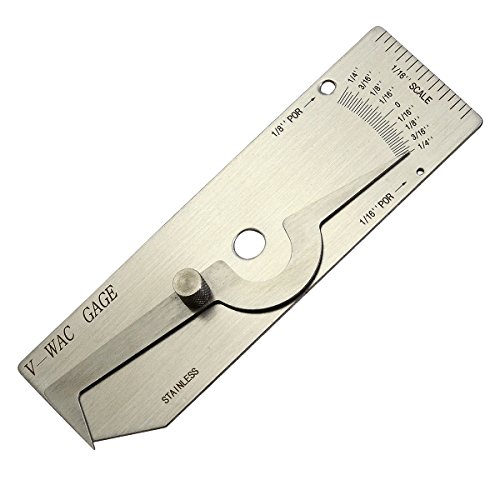
V-WAC Single Weld Gage
Common Travel Speed Mistakes to Avoid
- Using one IPM number for every weld. Speed must match the complete procedure.
- Assuming slower always means deeper penetration. An oversized puddle can cause cold lap and shallow fusion.
- Trying to fix bad settings with hand speed. Correct polarity, voltage, current or WFS, gas, and electrode first.
- Watching only the arc. Read the leading edge and both toes of the puddle.
- Changing angle or stickout while judging speed. Hold other technique variables steady.
- Using bead appearance as proof of strength. Perform the required inspection or test.
- Ignoring required weld size. Proper fillet weld sizing matters; an oversized bead can waste filler and increase heat without adding useful strength.
- Accelerating at the end without filling the crater. Use the machine’s crater-fill control, a brief backstep, a run-off tab, or the method specified by the procedure.
Products Worth Considering

🧲 Sticks to Toolboxes & Welders – Heavy-duty magnetic welding chart adheres to metal surfaces like your welding table, toolbox, or wall for instant reference while working.

PERFECT FIT: Designed for standard 8.5x11 inch paper size, making it easy to read and reference at a glance.

Richard Finch, Welder's Handbook: A Complete Guide to MIG, TIG, Arc & Oxyacetylene Welding, "Completely Revised and Updated Edition!" paperback
Frequently Asked Questions
What is the definition of travel speed in welding?
Travel speed is the rate at which the welding torch, gun, or electrode moves along the joint while the arc is on. It is commonly expressed in inches per minute or millimeters per minute.
What happens if welding travel speed is too fast?
Excessive speed can produce an undersized, narrow, or convex bead with poor toe tie-in, underfill, undercut, insufficient penetration, or incomplete fusion. Similar symptoms can also come from low heat, excessive electrode extension, or incorrect angle.
What happens if welding travel speed is too slow?
Excessively slow travel can create a wide or heavily convex bead, too much deposit, overlap, cold lap, shallow penetration, distortion, or burn-through on thin material. The large puddle can keep the arc from acting directly on the base metal.
How do you know if your travel speed is right?
The puddle should remain stable, the arc should stay at its leading edge, and the bead should meet the required size with smooth toe tie-in and no prohibited defects. For critical work, confirm the result with the inspection or testing required by the WPS or code.
How do you calculate welding travel speed?
Measure the weld length and arc-on time. For inches per minute, multiply the length in inches by 60 and divide by seconds. For millimeters per minute, multiply the length in millimeters by 60 and divide by seconds.
Does slower travel speed always increase penetration?
No. Slowing down from an excessive speed may improve penetration, but traveling too slowly can build a large puddle that absorbs arc energy and causes cold lap or shallow fusion. Penetration depends on the complete procedure, not travel speed alone.
How does wire feed speed affect travel speed in MIG welding?
In most constant-voltage MIG systems, increasing wire feed speed raises current and deposition rate. Travel speed may also need to increase to maintain the required bead size, but voltage, wire diameter, transfer mode, joint, and procedure limits must remain coordinated.
Should you increase travel speed near the end of a weld?
Do not accelerate automatically. Speeding up can leave an undersized end or an unfilled crater. Use the crater-fill setting, a brief backstep, a run-off tab, or the method required by the WPS. A procedure may call for a speed change as the part heats, but the crater still needs proper fill.
Conclusion
Travel speed shapes heat input per unit length, weld size, penetration, and toe tie-in, but it never works alone. Excessively fast travel can outrun the puddle, while excessively slow travel can build a large deposit that causes cold lap, poor fusion, overheating, or burn-through.
Start with the approved settings, hold angle and distance steady, measure a timed bead, and compare controlled test passes on representative scrap. Then verify the weld with the inspection or testing required for the job. That process turns travel speed from a guess into a repeatable welding variable.
Sources
- Miller Electric — MIG Welding: Setting the Correct Parameters — bead symptoms caused by excessive or insufficient travel speed and incorrect settings.
- Miller Electric — Five Steps to Improving Your Stick Welding Technique — leading-edge puddle control, cold lap, undercut, and travel-speed errors in SMAW.
- Miller Electric — Understanding the Basics of MIG Welding for Mild Steel — MIG angles, positions, electrode extension, puddle observation, and setup.
- Lincoln Electric — Variables That Affect Weld Penetration — interaction between travel speed and penetration.
- Lincoln Electric — True Energy — traditional and measured-energy heat-input calculations.
- OSHA — 29 CFR 1910.252, Welding, Cutting, and Brazing — eye protection, ventilation, hazardous coatings, cleaning compounds, and other welding safeguards.




