
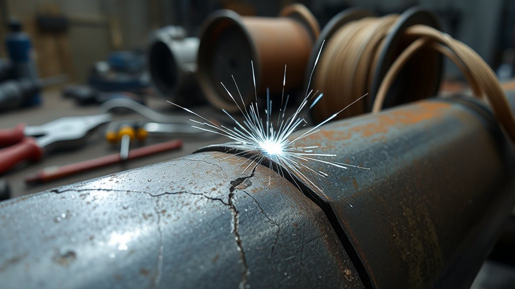
Welds usually crack after cooling because shrinkage stress becomes greater than the weld metal or heat-affected zone can handle. The trigger may be hydrogen, rapid or uneven cooling, a crack-sensitive material, high joint restraint, contamination, poor fit-up, an unsuitable filler metal, or an underfilled crater. Start by noting when the crack appeared, where it formed, and whether the material, consumables, settings, preparation, or cooling method changed.
Quick Answer
Welds crack after cooling when shrinkage stress, hydrogen, a brittle heat-affected zone, high restraint, contamination, or the wrong filler overwhelms the joint. Cracks during solidification are hot cracks; delayed cracks are often hydrogen-assisted. Remove the full crack, correct the cause, use the required heat control, and inspect the repair after cooling.
Key Takeaways
- Cracks that form during or just after solidification often involve bead shape, crater fill, alloy chemistry, contamination, or high restraint.
- Cracks that appear later in steel often involve hydrogen, a hard microstructure, tensile stress, and cooling that was too fast for the material.
- Preheat and interpass temperatures must come from the welding procedure, code, filler data, or material guidance—not guesswork.
- Low-hydrogen consumables only work as intended when they are selected correctly and stored according to the manufacturer’s instructions.
- Never weld over a crack. Remove it completely, fix the cause, reweld with the correct procedure, and inspect safety-critical work.
At a Glance
| Time Required | 10 to 30 minutes for basic diagnosis; longer for crack removal, controlled preheat, rewelding, cooling, and inspection. |
| Difficulty | Moderate for practice pieces; advanced for structural, pressure, lifting, trailer, frame, suspension, roll-cage, or code-governed welds. |
| Tools Needed | Wire brush, grinder or approved gouging equipment, non-chlorinated cleaner, temperature crayon or suitable thermometer, correct dry filler, PPE, and inspection tools as required. |
| Cost | Usually low for cleaning and setup corrections; higher when new filler, preheat equipment, nondestructive testing, engineering review, or professional repair is needed. |
Warning: Welding exposes you to fumes, ultraviolet radiation, burns, fire, electric shock, and hazards from coatings or residues. Follow OSHA welding ventilation and protection requirements. Never weld a sealed container or a tank, pipe, drum, or part that held fuel or flammable material unless it has been made safe under an approved procedure. Do not use chlorinated brake cleaner or allow chlorinated-solvent vapors near an arc.
Identify the Main Types and Causes of Weld Cracking
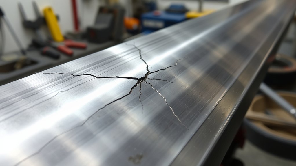
Most cracks that develop during welding or cooling fall into two broad groups: hot cracking and cold cracking. Hot cracks form while the weld metal or nearby material is still at a high temperature and losing ductility as it solidifies. Cold cracks form after solidification, often in a steel weld or heat-affected zone after the joint has cooled.
Hydrogen-assisted cold cracking in steel usually requires three conditions at the same time: diffusible hydrogen, a crack-sensitive or hard microstructure, and tensile stress. Thick sections, hardenable steels, high restraint, wet low-hydrogen consumables, dirty metal, and inadequate heat control can increase the risk. Delayed cracks may appear after the weld looks finished, so critical procedures may require a waiting period before final inspection.
Crack location also matters. A centerline crack often points to solidification behavior, bead shape, chemistry, or restraint. A crater crack forms at an underfilled stop. Toe, root, and heat-affected-zone cracks may involve high stress, undercut, lack of fusion, hydrogen, or hardening. A stepped crack in the base plate below a highly restrained weld may be lamellar tearing, which is linked to through-thickness shrinkage strain and poor through-thickness ductility.
Other defects are not cracks, but they can create stress points or weak sections. Porosity, slag inclusions, undercut, lack of fusion, and related problems such as worm tracks require their own diagnosis.
First, Identify When and Where the Crack Appears
Do not change random settings first. Record the crack timing, location, direction, and the material being welded. This narrows the likely cause.
| Crack Pattern | Likely Cause | What to Check First |
|---|---|---|
| Crack forms while the bead solidifies | Solidification cracking, unsuitable weld chemistry, poor bead profile, contamination, or high restraint | Filler compatibility, joint design, bead shape, travel speed, cleanliness, and restraint |
| Crack appears minutes or hours later in steel | Hydrogen-assisted cold cracking | Consumable exposure, moisture, base-metal hardenability, preheat, interpass temperature, heat input, and restraint |
| Star or split at the end of the weld | Crater cracking | Arc termination, crater fill, downslope, back-step, and stop-tab technique |
| Crack along the weld centerline | Solidification shrinkage, crack-sensitive chemistry, concave or narrow-deep profile, or high restraint | Filler selection, weld profile, joint design, travel speed, and weld sequence |
| Crack beside the weld in the HAZ | Hardening, hydrogen, rapid cooling, or high restraint | Verified material grade, carbon equivalent or hardenability, WPS preheat, filler hydrogen level, and cooling conditions |
| Stepped crack below the weld in the plate | Possible lamellar tearing | Joint orientation, through-thickness strain, plate quality, weld size, and restraint |
| Crack appears after repeated service loads | Fatigue, overload, poor detail design, or an earlier weld defect | Load path, vibration, weld toe profile, penetration, repair history, and engineering design |
Note: A crack is not the same as porosity, slag, undercut, or lack of fusion. Those discontinuities can weaken the joint or help a crack start, but any visible crack should be treated as serious until the part and repair method are evaluated.
How Hot and Cold Cracking Affect Your Welds
Hot cracking forms at high temperature while the weld metal or heat-affected zone has low ductility. It may follow the centerline, begin in the crater, or form along grain boundaries. Common contributors include crack-sensitive alloy chemistry, the wrong filler, a concave or narrow-deep bead, contamination, and joint restraint.
Cold cracking, also called hydrogen-assisted or delayed cracking, most often concerns carbon and low-alloy steels. Rapid cooling can create a hard microstructure, while hydrogen and residual tensile stress provide the other conditions needed for a crack. Miller’s hydrogen-control guidance explains why required preheat and interpass temperatures help slow cooling and give hydrogen more time to diffuse from the weld and HAZ.
Uneven cooling increases shrinkage stress because one area contracts while another resists movement. The answer is not simply “more heat.” Excess heat can enlarge the HAZ, increase distortion, alter strength, or damage some alloys. Follow the material guidance, filler data sheet, and welding procedure.
Process choice also changes the risk. Understanding where flux core welding is suitable helps you choose the correct wire, polarity, shielding method, cleaning routine, and heat range.
How Welding Technique Changes Crack Risk
Travel speed, voltage or arc length, current, electrode extension, heat input, bead profile, and joint preparation work together. Change one variable at a time and compare the result with the machine chart, filler data, or qualified procedure.
Welding Speed and Heat Input
Traveling too fast can produce a narrow, underfilled bead with poor tie-in or lack of fusion. On crack-sensitive steel, low heat input may also increase the cooling rate. Traveling too slowly can create an oversized pool, excessive heat input, distortion, burn-through, or a wide HAZ. The correct speed produces the required fusion and bead profile without exceeding procedure limits.
- Watch the leading edge: Keep the arc on the front of the puddle rather than outrunning it or burying it in an oversized pool.
- Keep bead size consistent: Sudden changes in speed create thin sections and stress concentrations.
- Follow process limits: On critical work, calculate or control heat input as required by the WPS instead of judging only by appearance.
Arc Length, Voltage, and Electrode Extension
“Arc length” does not mean the same adjustment for every process. Use the control that applies to your process:
| Process | What to Control | Crack-Related Problems From Poor Control |
|---|---|---|
| Stick (SMAW) | Keep a steady arc length suited to the electrode and position. | An overly long arc can increase spatter, undercut, and shielding problems; an arc that is too short can stick or make the bead irregular. |
| MIG or flux core (GMAW/FCAW) | Set voltage and maintain the recommended contact-tip-to-work distance or electrode extension. | Too much extension can reduce current and penetration on many constant-voltage setups; poor voltage or extension can cause undercut, porosity, lack of fusion, or an unstable bead. |
| TIG (GTAW) | Hold a short, steady arc without touching the tungsten to the puddle. | A long or wandering arc spreads heat and weakens shielding; tungsten contact can contaminate the weld. |
A steady setup helps prevent undercut, poor fusion, porosity, and sharp bead transitions that can become crack-starting points. For stick welding, use a reliable stick welder settings chart as a starting point, then confirm the electrode manufacturer’s range.
Joint Preparation and Restraint
Clean, even fit-up allows the weld to fuse and shrink more predictably. Poor preparation forces the bead to bridge gaps, fill tight spots, or compensate for misalignment.
- Remove contamination: Clean away rust, oil, paint, moisture, plating, heavy mill scale, slag, and cutting residue. Use only an approved non-chlorinated cleaner and let it evaporate fully before welding.
- Verify the joint dimensions: Check root opening, bevel angle, land, alignment, and backing against the drawing or WPS.
- Use the right filler: Match filler classification to the known base metal, process, required strength, position, service temperature, and code.
- Control restraint: Clamp enough to hold alignment, but use a sensible tack and weld sequence so shrinkage is not trapped unnecessarily.
- Avoid over-welding: Oversized welds add heat, filler, distortion, and shrinkage stress without automatically adding useful strength. Follow the specified size and the guidance on maximum fillet weld size.
Effective Strategies to Prevent Weld Cracking
Preventing weld cracking means controlling the specific mechanism, not using the same fix for every material.
- Identify the base metal. Do not guess on a critical repair. Use drawings, markings, mill certificates, manufacturer information, or material testing.
- Use compatible filler and polarity. Confirm the filler classification, shielding gas or flux requirements, polarity, position, and service conditions.
- Keep consumables in condition. Store low-hydrogen electrodes in sealed packaging or the specified holding oven after opening. Follow the manufacturer’s exposure and reconditioning limits.
- Use the required preheat. Check the WPS, code, material specification, or engineered repair procedure. Verify temperature in the specified area before welding and between passes.
- Control interpass temperature and heat input. Too little heat can increase cooling rate and fusion problems; too much can damage properties or widen the HAZ.
- Fill the crater. Pause, back-step, taper current, use a run-off tab, or use the machine’s crater-fill control as the procedure allows. Miller’s TIG troubleshooting guidance shows why abrupt stops leave crack-prone craters.
- Use a balanced weld sequence. Alternate sides or sequence passes as the procedure allows to reduce distortion and concentrated restraint.
- Let the joint cool as required. Do not quench a crack-sensitive weld. Protect it from cold drafts, rain, snow, or contact with a cold workbench when controlled cooling is required.
Pro Tip: If cracking began after a change in wire, rod, plate grade, thickness, shielding gas, or joint design, compare the old and new procedure before changing amperage. The new combination may require different filler, preheat, heat input, or inspection.
Shielding problems can add porosity, oxidation, and poor fusion. Check the recommended gas flow, hose and fitting leaks, nozzle condition, drafts, polarity, and contact-tip-to-work distance. More gas is not always better because excessive flow can create turbulence and pull air into the shielding envelope.
Products Worth Considering

Accurate, fast, low-cost method for measuring surface temperatures

Accurate results are +/- 1 percent of rated temperature; reliable always in calibration

Comprehensive Welding Package: our package comes with 24 low temperature universal welding rods available to meet your welding requirements; Whether you are a novice or an experienced welder, this kit of welding rods ensures you have things you need for your welding projects; Material is relatively brittle, received with breakage is a normal phenomenon, does not affect the use
Match the Procedure to the Base Material
Different metals crack for different reasons. Mild steel is often forgiving, but high-carbon steel, high-strength steel, cast iron, stainless steel, and aluminum can require very different filler and heat-control practices.
Material Compatibility Check
- Mild steel: Usually weldable with standard procedures, but contamination, restraint, poor fusion, wet consumables, and excessive cooling can still cause trouble.
- High-carbon, alloy, or high-strength steel: More likely to form a hard HAZ and hydrogen-assisted cracks. Verify the grade, thickness, filler hydrogen designation, preheat, interpass temperature, and heat input. When chemistry is known, carbon-equivalent methods can help qualified personnel judge weldability; AISC notes that valid chemistry data or laboratory testing is needed.
- Cast iron: Brittle material and steep temperature differences can create high thermal stress. The repair may require a nickel-based filler, controlled preheat or a cold-welding sequence, short beads, peening where appropriate, and slow cooling. The correct method depends on the cast iron type and part.
- Stainless steel: Grade identification, filler choice, dilution, joint restraint, shielding, and heat input matter. Some stainless combinations are more prone to solidification cracking, while excessive heat can reduce corrosion performance.
- Aluminum: Hydrogen causes porosity rather than hydrogen-assisted cold cracking. Most aluminum weld cracking is hot or solidification cracking, so base-alloy chemistry, filler choice, joint design, bead profile, and crater fill are central. See ESAB’s aluminum cracking guidance.
Flux core welding wire can work well for suitable steel applications, but the exact wire classification, polarity, shielding method, storage, stickout, and interpass cleaning still matter. Remove slag fully between passes so it cannot hide lack of fusion or become trapped in the joint.
Low-Hydrogen Filler Metals and Storage
Low-hydrogen filler metals can reduce diffusible hydrogen, but they do not correct the wrong base-metal identification, missing preheat, excessive restraint, or poor fusion. Use the filler classification required by the WPS or engineered repair.
Keep low-hydrogen stick electrodes in hermetically sealed packaging or the specified holding oven after opening. Follow the exact manufacturer limits for exposure and reconditioning. Do not improvise by heating rods in a kitchen oven, and do not oven-dry cellulosic electrodes such as E6010 or E6011; their coating is designed differently. Keep wire and flux clean, dry, and protected according to the product data sheet.
Use Post-Weld Heat Treatment Only When Specified
Post-weld heat treatment, hydrogen-diffusion holding, and stress relief are different operations. Each uses a controlled temperature, hold time, heating rate, cooling rate, and measurement method. The wrong cycle can reduce strength, toughness, hardness, or corrosion resistance. Do not apply PWHT to a critical part unless the material specification, code, WPS, manufacturer, or engineer requires and defines it.
What to Check Before You Weld Again
Do not place a new bead over the crack. Complete this checklist first:
- Crack location: Crater, centerline, toe, root, HAZ, base plate, or an old repair?
- Timing: During solidification, after cooling, the next day, or only after service loads?
- Material: Verified grade and condition—not just “steel” or “aluminum.”
- Joint: Root opening, bevel, alignment, backing, tack quality, weld size, and restraint.
- Contamination: Oil, rust, paint, zinc, plating, moisture, cutting residue, slag, or an unsafe cleaner.
- Consumables: Correct classification, diameter, polarity, shielding, lot condition, and storage history.
- Heat control: Required preheat, interpass range, heat input, postheat, and cooling method.
- Technique: Travel speed, work and travel angles, electrode extension, arc stability, toe tie-in, and crater fill.
- Inspection plan: Required cooling or delay before inspection and the correct nondestructive test for the part.
For a non-critical practice coupon, you may be able to remove the crack fully, correct the setup, and reweld. For structural members, pressure parts, trailers, vehicle frames, suspension parts, roll cages, lifting points, or any component whose failure could injure someone, stop and use a qualified repair procedure and inspector.
Remove, Reweld, and Inspect the Crack Correctly
- Take the part out of service. Do not load, bend, pressure-test, or “see if it holds” before the crack is evaluated.
- Find the crack ends. Clean the area and use the inspection method suited to the material and crack. A surface mark may not show the full length.
- Remove the complete crack. Grind, machine, or gouge using the approved repair method until sound metal remains. Do not leave the crack root under the groove.
- Confirm removal. Visual inspection alone may be insufficient. Dye penetrant can find surface-breaking cracks on many nonporous metals; magnetic-particle testing applies to ferromagnetic materials; ultrasonic or radiographic methods may be required for internal flaws.
- Correct the cause. Change the filler, joint preparation, restraint, preheat, sequence, shielding, heat input, or stop technique as required.
- Reweld to the procedure. Maintain the specified temperatures and clean each pass. Avoid undercut, lack of fusion, sharp toes, concave craters, and oversized beads.
- Inspect after the required cooling or delay. Hydrogen-assisted cracking can be delayed, so critical codes or procedures may require inspection after a set hold time rather than immediately after welding.
Note: Drilling a hole at a visible crack tip is not a complete weld repair unless an approved engineering procedure specifically calls for it. The crack can extend beyond what you can see, and the damaged joint still needs a qualified repair.
A crack is a failure warning, not a cosmetic flaw. The safe repair removes the full crack, corrects the mechanism that caused it, and verifies the finished weld after the required cooling or delay.
Products Worth Considering

Standard grade kit

Easy to use windshield repair system that allows for Do-It-Yourself repairs of windshield damage

The Dye Penetrant Crack Finder Kit (For Cast Iron and Aluminum) is a simple 4 step process that eas
Common Mistakes That Make Weld Cracking Worse
- Welding over the crack: The new bead can hide the indication while the original crack remains below it.
- Guessing the preheat: A random temperature may be too low to help or high enough to harm the material.
- Quenching the weld: Water, compressed air, snow, or a cold surface can increase thermal gradients and hardening in susceptible steel.
- Using any rod labeled “stronger”: Higher deposited strength is not automatically safer and may increase crack sensitivity or mismatch the base metal.
- Baking every electrode: Low-hydrogen and cellulosic electrodes have different storage requirements.
- Assuming a clean-looking weld is sound: Delayed and subsurface cracks may require time and nondestructive testing to reveal.
Frequently Asked Questions
Why do my welds keep cracking after they cool?
Repeated cracking means the root cause is still present. Common causes include hydrogen, fast cooling, hardenable steel, high restraint, poor joint design, incompatible filler, contamination, lack of fusion, and an underfilled crater. Record the timing and location, identify the material, and correct the procedure before trying again.
How do you fix a cracked weld?
Take the part out of service, find the full crack, remove it to sound metal, verify removal, correct the cause, and reweld with the proper filler and heat control. Inspect the repair after the required cooling or delay. Safety-critical parts need a qualified procedure and inspector.
How do I prevent cold cracking in steel?
Control all three conditions behind hydrogen-assisted cracking: diffusible hydrogen, a hard crack-sensitive microstructure, and tensile stress. Use the specified low-hydrogen process, dry consumables, required preheat and interpass temperature, suitable heat input, clean metal, and a joint sequence that limits restraint.
What happens if my weld heat input is too low?
Heat input that is too low for the joint can cause poor fusion, shallow penetration, a narrow bead, and fast cooling. On hardenable steel, faster cooling can create a harder HAZ and raise delayed-cracking risk. Use the approved parameter range rather than increasing heat without limits.
Can I grind out a cracked weld and reweld it?
Yes on suitable work, but only when the full crack is removed and the cause is corrected. The groove shape, filler, preheat, sequence, and inspection must suit the part. Structural, pressure, lifting, vehicle, and other safety-related repairs should be handled under a qualified procedure.
Why does my weld crack at the end of the bead?
A crack at the stop is often a crater crack. The arc ended before enough filler metal supported the shrinking puddle. Use the approved pause, back-step, downslope, run-off tab, or crater-fill control so the weld does not end in a deep concave pocket.
How long after welding can a hydrogen crack appear?
It may appear after the weld has cooled rather than immediately. The exact delay depends on the steel, hydrogen level, stress, thickness, temperature, and procedure. Critical codes and WPSs may require a specific waiting period before final nondestructive testing, so follow the governing requirement.
Can aluminum get hydrogen cold cracks?
No. In aluminum welding, hydrogen mainly causes porosity, not hydrogen-assisted cold cracking. Aluminum cracks are usually hot or solidification cracks linked to alloy chemistry, filler selection, joint design, restraint, bead profile, or crater fill.
Conclusion
Welds crack after cooling when stress acts on weld metal or a heat-affected zone that cannot deform safely. The cause may be hydrogen, rapid cooling, a hard or crack-sensitive material, poor filler selection, contamination, joint restraint, bad fit-up, incomplete fusion, or a weak crater. Identify the crack timing and location, verify the material, remove the full crack, correct the procedure, and inspect the repair after the required cooling or delay. Do not return a structural or safety-critical part to service based on appearance alone.
Sources
- OSHA 29 CFR 1910.252, General Requirements for Welding, Cutting, and Brazing — ventilation, coatings, cleaning compounds, confined spaces, and welding safety requirements.
- CDC/NIOSH Welding Fumes and Manganese — health risks and exposure-control resources for welding fumes.
- MillerWelds: How to Control Hydrogen in Welding — hydrogen sources, low-hydrogen consumable storage, preheat, interpass temperature, and diffusion control.
- MillerWelds: Common TIG Welding Problems — crater cracking, arc termination, and base-metal cleanliness.
- ESAB: Proven Techniques to Prevent Cracking in Aluminum Alloys — aluminum solidification cracking, filler compatibility, joint design, and crater control.
- Federal Highway Administration Weld-Cracking Investigation — field evidence linking hydrogen, inadequate preheat, restraint, weld stops, and crack prevention.




