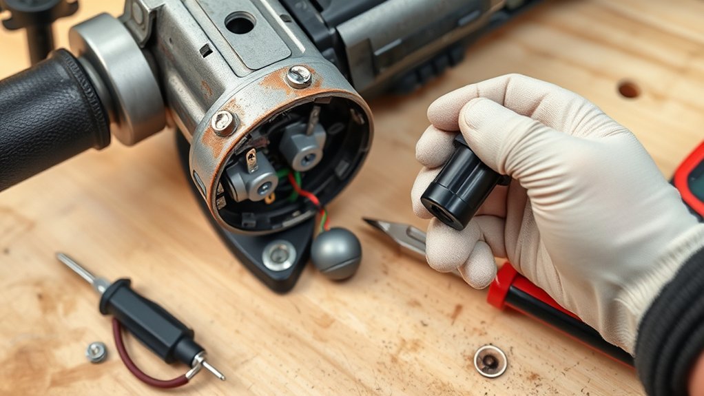
Replacing an angle grinder switch can restore reliable on/off control, but it is an electrical repair with real startup and laceration risks. Before opening the tool, unplug a corded grinder or remove the battery, take off the wheel, confirm the exact model and type number, and check the manufacturer’s parts diagram. Stop if the wiring is burned, the housing is melted, or the circuit layout is unclear.
Quick Answer
To replace an angle grinder switch, disconnect all power, remove the wheel, identify the exact model-specific switch assembly, photograph and label every wire, remove the old switch, reconnect the matching replacement, close the housing completely, and perform a controlled no-load test. Do not proceed with burned wiring, uncertain terminals, or a recalled tool.
Key Takeaways
- Unplug the grinder or remove its battery before servicing it, and never energize the tool with the housing open.
- Match the replacement by model number, type number, service part number, terminal layout, and electrical rating—not appearance alone.
- Photograph and label the wiring before disconnecting it; do not rely on wire color alone.
- Use continuity mode only on a de-energized, electrically isolated switch.
- Stop using the grinder if the switch sticks, starts the tool unexpectedly, will not shut it off, or shows heat damage.
At a Glance
| Time Required | About 30 to 60 minutes for a simple, accessible switch; longer if diagnosis or model-specific disassembly is needed |
| Difficulty | Moderate to advanced; not suitable when wiring is burned, undocumented, or integrated with electronic controls |
| Tools Needed | Correct screwdrivers or bits, needle-nose pliers, labels or masking tape, phone or camera, small screw tray, model-specific switch, and an optional digital multimeter with continuity mode |
| Cost | Varies by model and whether the switch is sold alone or as part of a wiring or electronic control assembly |
How to Replace an Angle Grinder Switch: Step-by-Step Overview
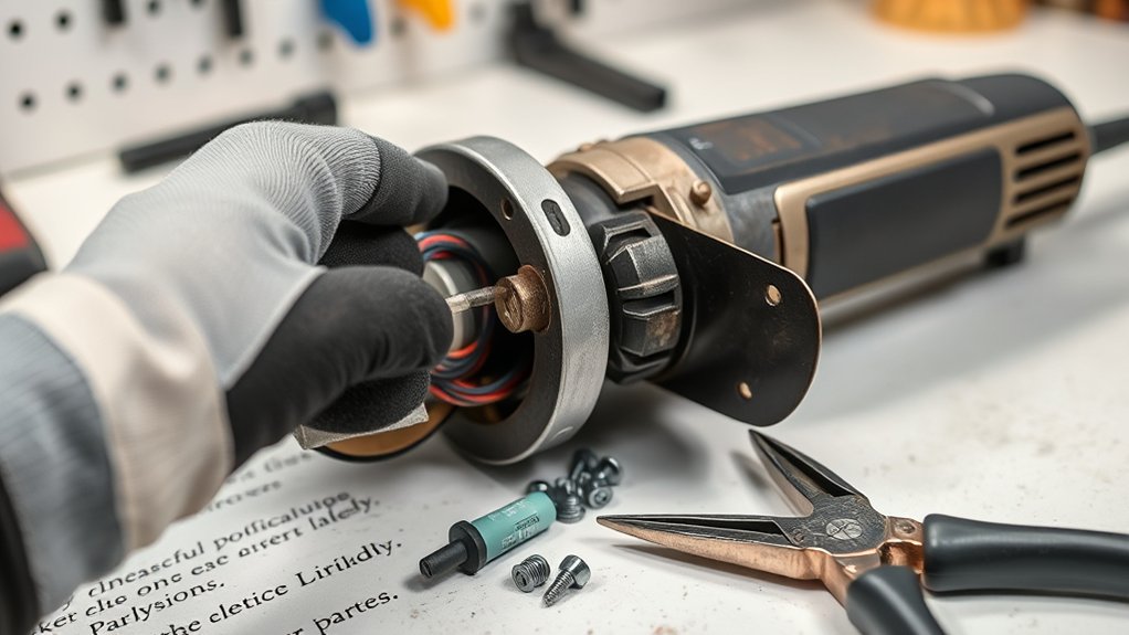
A switch that works only when wiggled, cuts out during use, sticks in the on position, or fails to stop the grinder needs immediate attention. Manufacturer safety instructions state that a power tool that cannot be controlled by its switch is dangerous and must be repaired. The safest repair path is to diagnose the fault first, use the exact service part, document every connection, and keep the tool de-energized until the housing is fully closed.
Warning: Never work on a plugged-in angle grinder or a cordless grinder with its battery installed. Remove the wheel before opening the housing. Do not power the tool with the casing open. If you smell burning or find melted plastic, scorched terminals, cracked insulation, or a swollen battery, stop and use an authorized repair service.
The repair sequence is:
- Confirm the symptom. Rule out the outlet, extension cord, battery, charger, brushes, and obvious cord damage.
- Identify the tool exactly. Record the brand, model number, type number, serial or date code, voltage, and switch service part number.
- Check the manual, parts diagram, warranty, and recalls. Some grinders require a complete switch, harness, or controller assembly rather than a stand-alone switch.
- Disconnect power and remove the wheel. Leave the guard installed unless the model-specific service procedure requires its removal.
- Open the correct housing section. Keep screws organized by length and location.
- Photograph and label the wiring. Capture several angles before moving any terminal.
- Remove and inspect the old switch. Check the terminals, cord entry, strain relief, wiring, and surrounding plastic for heat damage.
- Install the matching replacement. Route each wire exactly as before and make sure the actuator, lock-off, and return spring move freely.
- Close and inspect the housing. Confirm that no wire is pinched and all fasteners are installed.
- Test in controlled stages. Check mechanical movement first, then perform a brief powered function test and a guarded no-load accessory test as the manufacturer directs.
Diagnose the Problem Before Replacing the Switch
A grinder that will not start does not automatically have a bad switch. A damaged power cord, failed outlet, tripped breaker, discharged or defective battery, worn carbon brushes, overheated motor, broken internal lead, failed electronic controller, or motor fault can create similar symptoms.
| Symptom | Possible Causes | First Safe Check |
| No response at all | Outlet, plug, cord, battery, brushes, switch, controller, or motor | Test the power source and inspect the cord or battery before opening the tool |
| Starts only when the switch or cord is moved | Worn contacts, loose terminal, broken conductor, or damaged strain relief | Stop using it; inspect the switch, terminals, cord entry, and wiring while de-energized |
| Runs after release or starts when connected to power | Stuck switch, incorrect wiring, damaged lock-on mechanism, or failed electronic control | Disconnect power immediately and do not test again until the fault is corrected |
| Burning odor, smoke, or localized heat | Loose high-resistance connection, overloaded switch, damaged wiring, motor fault, or controller failure | Stop use and seek professional diagnosis; replacing only the switch may not correct the cause |
Note: Some brushless cordless grinders combine the switch, wiring harness, electronic brake, and motor controller functions. Use the exact exploded diagram for your model before assuming the visible actuator is a separate service part.
Identify the Exact Model, Part, Warranty, and Recall Status
Do not buy a switch by brand name or visual similarity alone. Record every identifier on the rating plate. Depending on the manufacturer, the type number, serial number, or date code can be as important as the model number because one model may use different internal parts across production revisions.
Use the manufacturer’s model- and type-specific parts diagram to confirm:
- The switch or switch-assembly service part number
- The tool’s model and type or production revision
- The terminal count and layout
- The voltage and current rating shown on the original part
- The actuator, lock-off, lock-on, return spring, and housing fit
- Whether the switch is sold separately or with a wiring harness or electronic module
Before opening the grinder, check its warranty terms and search the U.S. Consumer Product Safety Commission recall database by brand and model. A recalled grinder may qualify for a manufacturer repair, replacement, or refund. Do not substitute a DIY switch repair for an official recall remedy.
Pro Tip: Photograph the rating plate and old switch markings before ordering. For manufacturers that use type numbers, search with both the model and type number so the parts diagram matches the exact tool revision.
Products Worth Considering

Angle grinder release switch made of plastic and metal material, which is sturdy, durable and practical for a long time.

Brand New and Unused: This replacement switch is a brand-new, unused part specifically designed for DeWalt angle grinders, ensuring top-notch quality and performance.
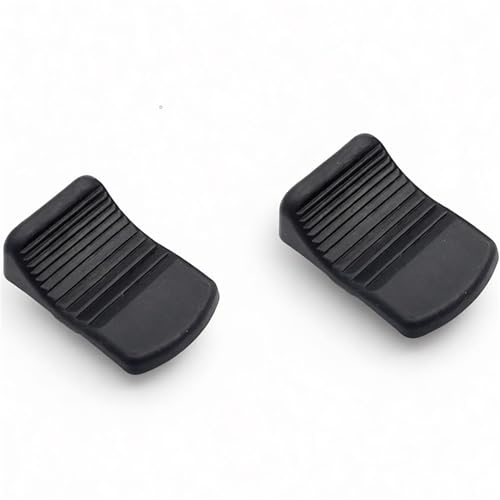
include 2 Grinder knob
Understanding the Importance of Your Angle Grinder Switch
Your angle grinder’s switch controls whether power reaches the motor and, on some models, works with a lock-off, lock-on, electronic brake, soft start, or restart-prevention system. A reliable switch gives predictable control. A worn, sticking, or incorrectly installed switch can cause delayed starting, random stopping, failure to shut off, or unexpected activation.
Understanding the switch matters for several reasons:
- Safety: The tool must start and stop when expected. A switch that cannot control the grinder makes the tool unsafe to use.
- Control: Paddle, slide, trigger, and other actuator styles behave differently, especially when lock-on or lock-off features are present.
- Compatibility: The internal switch assembly must match the tool’s electrical design and housing, not just the outside button shape.
- Diagnosis: Intermittent operation may come from the switch, cord, terminal, brushes, controller, or motor, so symptoms need to be traced rather than guessed.
- Service quality: Correct wire routing, strain relief, insulation, and fastener placement are part of the repair, not optional finishing details.
A power tool that cannot be controlled reliably by its switch is unsafe and should be repaired before further use.
Signs Your Angle Grinder Switch May Need Replacement
Look for a pattern of symptoms rather than relying on one sign. Normal motor warmth or a single failed start does not prove the switch is bad, but repeated control problems require the grinder to be removed from service.
Common warning signs include:
- The grinder does not respond even though the power source, cord or battery, and brushes have been checked.
- The switch clicks, but the motor does not start.
- The grinder starts and stops when the switch body, cord, or housing is moved.
- The switch feels cracked, jammed, gritty, loose, or fails to return normally.
- The grinder keeps running after the paddle or trigger is released.
- The tool starts as soon as it is plugged in or the battery is installed.
- There is discoloration, melted plastic, visible arcing, smoke, or a burning smell near the switch.
- The lock-on or lock-off mechanism does not engage or release correctly.
If the switch is physically damaged or unreliable, do not continue using the grinder. A tool that cannot be shut off quickly is especially dangerous with a cutting wheel, wire wheel, or heavy grinding disc installed.
Identifying Common Types of Angle Grinder Switches
There is no universal fixed count of angle grinder switch types. Manufacturers use several external actuator styles and many internal switch assemblies. The common external controls below describe how the user operates the tool; they do not identify a compatible replacement part by themselves.
- Paddle switch: Usually held by the fingers or palm. Many designs include a lock-off lever and stop when pressure is released.
- Slide switch: Slides forward or backward and may include a lock-on position for continuous operation.
- Trigger switch: Common on rear-handle or larger grinders and may include a lock-off or lock-on control.
- Thumb, rocker, or toggle-style actuator: Used on some compact, specialty, or older tools; the internal mechanism varies widely.
Match the replacement to the exact model, type number, service part number, terminal layout, voltage and current rating, actuator travel, mounting tabs, and housing fit. A switch that looks similar may still be unsafe if its contact arrangement or mechanical return differs.
Products Worth Considering


This is Brand New – Unused replacement switch for DeWalt angle grinder.

Compatibility: Compatible with Bosch 6-100, GWS6/8-100, S1M-FF03-100A, TWS6600 angle grinders for easy swap.
Guide to Safely Remove Your Old Switch
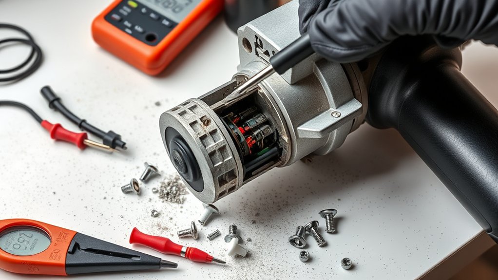
Before removing the old switch, disconnect the tool from every power source. Unplug a corded grinder; remove a detachable battery from a cordless grinder. Let the tool cool, remove the wheel, clean loose dust from the outside, and work on a dry, well-lit bench.
Safety Precautions First
- Wear safety glasses while opening dusty or spring-loaded housings.
- Remove the grinding or cutting wheel before disassembly.
- Keep the battery away from loose screws, terminals, and other metal objects.
- Use a screw tray and arrange fasteners by location and length.
- Take several photos before disconnecting wires or moving springs.
- Do not pull a connector by its wire; grip the terminal body when possible.
- Do not force the casing apart. Recheck for hidden screws, labels, clips, or interlocking tabs.
- Do not bypass, tape down, or permanently defeat a lock-off, dead-man, or safety switch.
- Do not apply power while the tool housing is open.
Tools Required for Removal
Use the correct Phillips, Torx, hex, or security bit so the casing screws are not stripped. Needle-nose pliers can help remove push-on terminals, but use them gently and pull on the connector rather than the conductor. Labels, masking tape, and a fine marker make wire identification easier. A small container keeps screws, springs, and levers together.
A digital multimeter with continuity mode is optional and should be used only on a de-energized, isolated component. A non-contact voltage tester is not a substitute for physically unplugging the grinder or removing its battery.
Step-by-Step Switch Removal
- Disconnect power. Unplug the grinder or remove the battery and keep the power source away from the bench.
- Remove the wheel. Take off the disc or wheel and secure or remove any loose flange hardware as the manual directs. Leave the guard installed unless the service procedure requires removal.
- Remove the side handle if it blocks access. Do not remove unrelated parts.
- Open the switch housing. Remove the correct casing screws and separate the halves slowly so springs, levers, and wires remain in place.
- Locate the switch and strain relief. Trace the cord or battery leads to the switch and note any suppression components, controller leads, or brush connections.
- Document the wiring. Take close photos from several angles and label every lead by terminal position.
- Disconnect the wires. Release terminal screws, push-on connectors, locking tabs, or plug housings without twisting or pulling the conductor.
- Release the switch. Remove its screws, clips, cradle, actuator, or spring in the order shown by the parts diagram.
- Inspect the surrounding parts. Look for heat-darkened terminals, loose crimp connections, cut insulation, pinched leads, damaged strain relief, carbon dust, and melted plastic.
If the old switch is melted, badly discolored, or fused to the housing, do not pry it out and install another switch without finding the cause. Heat damage can result from a loose terminal, overload, incorrect part, motor problem, or electronic fault.
How to Test the Old Switch for Continuity
A continuity test on a de-energized, isolated component can help confirm whether a simple mechanical switch opens and closes, but it does not prove that the switch can safely carry full motor current. It also may not apply to electronic or multi-function switch modules.
- Unplug the grinder or remove the battery.
- Photograph and label the switch wiring.
- Disconnect the switch from the circuit, or isolate the terminals being tested so another component cannot create a parallel path.
- Set the multimeter to continuity mode and verify the meter by touching the probes together.
- Use the parts diagram or markings to identify the correct input and output terminals.
- With the switch off, the tested contact pair should normally read open and produce no continuity tone.
- With the switch on, a simple contact pair should normally show continuity and low resistance.
- Operate the switch several times. Intermittent readings, high or unstable resistance, or continuity in the off position indicate a faulty contact or incorrect terminal selection.
Warning: Never use resistance or continuity mode on an energized circuit. Do not probe a battery-powered grinder with the battery installed. If you cannot identify the terminals from the diagram, stop rather than guessing.
Installing Your New Angle Grinder Switch
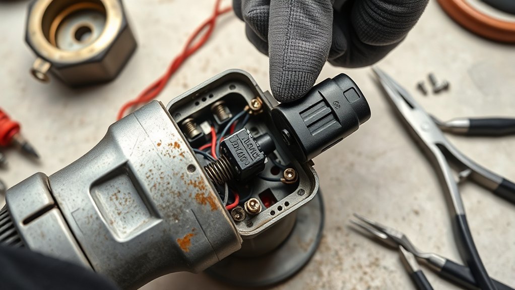
Compare the new switch or switch assembly with the old part before making any connection. The service part number, housing shape, mounting points, actuator movement, terminal layout, and rating markings should agree with the manufacturer’s parts information.
Follow these steps:
- Transfer only approved reusable parts. Move the actuator, spring, boot, or cradle only if the parts diagram shows that they are separate and reusable.
- Seat the switch correctly. Make sure it lies flat in its molded pocket and cannot shift when operated.
- Reconnect one wire at a time. Use the photos, labels, and diagram. Do not rely on color alone.
- Check every terminal. Push-on connectors should fit firmly; screw terminals should be secure without cutting or crushing the conductor.
- Restore the original wire routing. Keep wires away from the armature, fan, switch actuator, screw bosses, sharp edges, and casing seam.
- Seat the cord strain relief or battery-terminal block. The cord must not slide, twist, or pull on the switch terminals.
- Test the mechanism while unplugged. Operate the switch several times. The lock-off, lock-on, paddle, trigger, or slide should move and return exactly as designed.
- Close the housing slowly. Stop if the casing does not meet without force; a wire, spring, or switch may be out of position.
- Install and tighten all screws evenly. Use the correct screws in their original locations and do not overtighten plastic bosses.
Pro Tip: Before closing the casing, compare your final wire routing with the first photos. Look closely at screw posts and the perimeter seam, where pinched insulation is easy to miss.
Testing the Grinder After Switch Replacement
Testing is part of the repair, not an optional step. The housing must be fully closed, all fasteners must be installed, and the switch must be in the off position before power is restored.
1. Complete the Unpowered Checks
- Operate the switch, lock-off, and lock-on features several times.
- Confirm the switch returns or stays in position exactly as the model is designed to operate.
- Inspect the casing seam for gaps and trapped wires.
- Confirm the cord strain relief or battery terminal block is secure.
- Make sure no flange, nut, washer, key, or tool is loose on the spindle.
2. Perform the First Powered Function Test
Check the manufacturer’s manual before running the grinder without an accessory. If a no-accessory test is permitted, make sure no loose mounting hardware can spin free. Otherwise, install the correct guard and a known-good accessory exactly as the manual directs before the first powered test.
- Move to a clear, dry area away from flammable materials and bystanders.
- Confirm the switch is off before connecting the plug or battery.
- Hold the grinder firmly with both hands and keep the tool pointed in a safe direction.
- Start it briefly and release or move the switch to off.
- Confirm that it starts normally, stops when commanded, and does not restart when the switch is off.
- Listen for unusual buzzing, clicking, scraping, or surging.
- Disconnect power and inspect for odor, smoke, abnormal heat, or a shifting housing.
3. Reinstall the Guard, Wheel, and Side Handle
Install the correct guard, flange, wheel, and side handle according to the grinder manual. Inspect the wheel for damage and verify that its size, type, arbor, and rated speed match the tool. With the grinder fully assembled, position yourself and bystanders away from the wheel’s plane and run the tool at no load for the period specified by the manufacturer; many grinder manuals call for a one-minute test after installing a wheel.
Warning: Unplug the grinder immediately if it starts when connected to power, continues running after the switch is released, has a failed lock-off, surges, smokes, smells burned, or becomes hot near the switch. Do not repeat the test until the fault is identified.
What to Do If Your Grinder Won’t Turn On
If the grinder still will not start, return to diagnosis instead of replacing more parts at random. Check the power source first, then follow the circuit path through the cord or battery connection, switch, brushes or electronic controller, and motor.
Possible Power Issues
- Test the wall outlet with another known-working device.
- Check the breaker, fuse, extension cord, or power strip.
- Inspect the plug and cord for cuts, crushed areas, burns, loose blades, or damaged strain relief.
- For a cordless model, charge the battery and try a known-good compatible battery if available.
- Inspect battery contacts for dirt, corrosion, overheating, or physical damage.
- Allow an overheated tool or battery to cool according to the manual before retesting.
- Check replaceable carbon brushes for wear, sticking, damaged leads, or incorrect seating.
If these checks do not identify the fault, consult the manufacturer’s manual and parts diagram. Do not keep cycling power to a grinder that smells hot, trips a breaker, or shows electrical damage.
Check Internal Wiring
With the grinder unplugged or the battery removed, inspect the wiring near the cord entry, switch terminals, brush holders, controller plugs, and tight bends. Look for loose terminals, darkened copper, cut or pinched insulation, broken strands, melted connectors, and conductors pulled tight across moving parts.
Do not repair damaged mains-voltage wiring with ordinary tape, improvised splices, or unmatched connectors. The insulation, conductor size, terminal, routing, and strain relief must be suitable for the tool. If a lead or harness is damaged, use the manufacturer-approved service part or an authorized repair center.
If the New Switch Does Not Fix the Problem
A new switch that tests correctly but does not restore operation may point to worn brushes, an open power cord, a failed thermal protector, a broken field or armature winding, a damaged battery connection, or an electronic controller fault. On a brushless grinder, diagnosis may require model-specific test procedures and equipment that are not appropriate for a general DIY repair.
Common Mistakes to Avoid
- Ordering by appearance: Similar-looking switches may have different terminal arrangements, ratings, or actuator travel.
- Ignoring the type number: A model can have more than one production revision and parts list.
- Skipping the recall check: An official remedy may be safer and may cost nothing.
- Forgetting photos and labels: Wire colors can repeat or vary across revisions.
- Testing continuity with power connected: Resistance and continuity modes are for de-energized circuits.
- Pulling on wires: This can loosen crimps or break conductors inside the insulation.
- Pinching wires during reassembly: Trapped insulation can cause a short circuit or expose live metal.
- Defeating a lock-off or dead-man feature: Never tape down, bypass, or permanently lock a safety control.
- Powering the grinder with the housing open: This exposes live parts and moving components.
- Testing with loose spindle hardware: A free flange or nut can become a projectile or damage the tool.
- Assuming the switch caused heat damage: A loose terminal, overload, motor fault, or wrong replacement part may be the underlying cause.
- Reinstalling the wheel without the guard: The guard must be correctly fitted and positioned for the accessory and operation.
When to Repair or Replace the Grinder
A switch replacement can make sense when the grinder is otherwise sound, the correct service part is available, the wiring and housing are undamaged, and the repair cost is reasonable compared with the tool’s value.
Use an authorized repair service or replace the grinder when you find:
- Burned wiring, melted terminals, or heat-damaged housing
- A cracked casing, gear case, guard mount, or battery interface
- Severe bearing noise, spindle play, or gear damage
- A damaged motor, armature, field winding, or electronic controller
- An unavailable or discontinued safety-critical switch assembly
- Repeated switch failure without a confirmed cause
- A recall that directs owners to stop use and obtain an official remedy
- Unclear wiring, missing diagrams, or a repair beyond your electrical experience
Manufacturer guidance commonly calls for power-tool service by a qualified repair person using identical replacement parts. That is the better option whenever the repair involves burned conductors, electronic modules, battery damage, or uncertain terminal identification.
Frequently Asked Questions
How many different types of switches are used with angle grinders?
There is no universal fixed number. Common external controls include paddle, slide, trigger, thumb, rocker, and toggle-style actuators, but the internal switch assemblies vary by model and production revision. Match the service part number and type number rather than choosing by switch style alone.
How do you fix an angle grinder that is not turning on?
Check the outlet or battery, plug, cord, strain relief, brushes, and visible wiring before blaming the switch. If a simple isolated switch fails a continuity test or has mechanical damage, replace it with the exact model-specific part. Electronic or brushless models may need professional diagnosis.
What safety check should you perform before switching an angle grinder on?
Confirm the housing is fully closed, the switch is off, the cord or battery is undamaged, the guard and side handle are secure, the wheel is correct and uncracked, the flanges are properly fitted, and no tool or hardware is loose. Keep people out of the wheel’s plane during the no-load test.
What is a slide switch on an angle grinder?
A slide switch turns the grinder on by moving a control along the tool body. Some designs can lock on for continuous use, while others include restart protection or a separate lock-off. The replacement must match the original mechanical and electrical design.
Can you replace an angle grinder switch yourself?
A careful DIYer may replace a simple, accessible switch when the exact part and wiring diagram are available. Use professional service if the wiring is burned, the switch is integrated with electronics, the terminals are unclear, the housing is damaged, or the repair is covered by a recall or warranty.
Why does my grinder only start when I wiggle the switch?
Possible causes include worn switch contacts, a loose terminal, a broken conductor near the cord entry, or a damaged internal connector. Stop using the grinder because movement-sensitive power can become an unexpected-start or failure-to-stop hazard.
Can I bypass an angle grinder safety switch or lock-off?
No. Do not bypass, tape down, remove, or permanently defeat a lock-off, dead-man, or other safety control. Install the correct replacement assembly or have the grinder repaired by an authorized service center.
How do I test an angle grinder switch with a multimeter?
Disconnect all power, isolate the switch from the rest of the circuit, select continuity mode, and probe the correct contact pair identified by the diagram. A simple switch normally reads open when off and shows continuity when on. Do not use continuity mode on an energized tool.
Should I check for a recall before replacing the switch?
Yes. Search the CPSC recall database and the manufacturer’s support site using the exact model and serial or date code. If the tool is recalled, follow the official remedy instead of performing an unofficial repair.
Conclusion
Replacing an angle grinder switch can restore safe control when the fault is correctly diagnosed and the exact service part is used. Disconnect power, remove the wheel, document every connection, test only on a de-energized isolated switch, route wires exactly as designed, and close the housing completely before restoring power.
Do not guess when the grinder has burned wiring, melted plastic, an integrated electronic controller, a damaged battery, or unclear terminals. Check the model, type number, parts diagram, warranty, and recall status first. After installation, confirm the switch action while unplugged, then perform a controlled powered test and a guarded no-load wheel test according to the manufacturer’s manual.
Sources
- OSHA: Hand and Power Tools — disconnecting tools before service, avoiding accidental starts, and portable abrasive-wheel safety.
- OSHA 29 CFR 1910.243: Guarding of Portable Powered Tools — guard requirements for portable grinders.
- DEWALT DCG416 Angle Grinder Instruction Manual — switch safety, servicing with identical parts, guard use, and no-load accessory testing.
- DEWALT: Manuals, Parts Lists, and Diagrams — model and type-number matching for service information.
- Fluke: How to Test for Continuity — de-energized and isolated continuity-testing procedure.
- CPSC: Metabo Angle Grinder Switch Recall — documented hazard from a switch sticking in the on position.