
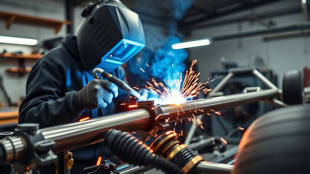
Race car welding punishes small mistakes. A dirty joint, loose fit-up, wrong filler, poor ground connection, or unapproved process can turn a clean-looking bead into a failure point under track loads. Before welding any part, identify the metal, check the current rulebook or repair procedure, isolate fuel and electrical hazards, test the setup on matching scrap, and decide how the finished weld will be inspected.
Quick Answer
For most race car fabrication, use MIG or DCEN TIG on mild steel, AC TIG or a suitable MIG setup on weldable aluminum, and TIG on 4130 when the current rulebook or approved procedure requires it. Identify the alloy first, isolate fuel and electronics, clean to bare metal, test on matching scrap, control heat, and inspect every critical joint.
Key Takeaways
- Check the current sanctioning-body rules, drawing, and approved welding procedure before choosing MIG or TIG.
- Identify the base alloy and condition before selecting ER70S, ER80S, 4043, 4943, 5356, or stainless filler.
- Disconnect and protect fuel, battery, airbag, wiring, and electronic systems according to the vehicle manufacturer’s instructions.
- Clean to sound metal, use tight fit-up, and prove the setup on a coupon that matches the real joint.
- Use short, controlled arc time for thin sheet, but follow the drawing when a structural joint requires a continuous weld.
- Do not rely on appearance alone for steering, suspension, rollover, braking, seat, restraint, or other critical welds.
At a Glance
| Time Required | Allow time for hazard isolation, preparation, matching test coupons, welding, cooling, and inspection. Total fabrication time depends on access and joint count. |
| Difficulty | Intermediate for noncritical mild-steel tabs and brackets; advanced or professional for cages, chassis tubes, suspension, steering, seat mounts, restraints, brakes, and fuel-system areas. |
| Tools Needed | Correctly equipped welder, helmet, gloves, flame-resistant clothing, local fume extraction, extinguisher, preparation tools, clamps or fixtures, measuring tools, and matching test material. |
| Cost | Varies widely. Gas, filler, abrasives, coupons, fixturing, professional inspection, chassis certification, and repairs may cost more than the weld itself. |
Choose the Right Welding Process and Check the Rulebook
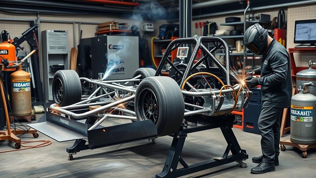
Do not choose a welding process from the metal name alone. Material thickness, joint design, access, required penetration, heat treatment, production rules, and your ability to repeat the procedure all matter.
Miller’s TIG guidance identifies AC as the usual TIG setting for aluminum and DC electrode negative, or DCEN, as the normal TIG polarity for steel and common steel alloys. Aluminum can also be MIG-welded when the machine, gun or spool gun, wire, gas, and transfer mode are suitable.
| Material or Job | Common Process | Main Limit |
|---|---|---|
| Mild-steel tabs, brackets, sheet, and permitted chassis work | MIG or DCEN TIG | Use the process allowed by the drawing, repair procedure, and rulebook. |
| 4130 chromoly tube | Usually TIG for critical motorsport structures | Some classes specifically require approved TIG welding and chassis inspection. |
| Weldable aluminum panels, pipe, tanks, and brackets | AC TIG or properly equipped MIG | Base-alloy identification, oxide removal, filler selection, and cleanliness are essential. |
| 304 stainless exhaust or brackets | DCEN TIG or suitable MIG | Match the filler and shielding setup to both metals being joined. |
The rulebook can be more restrictive than general welding advice. For example, the 2026 FIA Drag Racing Sportsman Regulations specify approved TIG welding for certain 4130/Docol roll-cage work while allowing approved MIG or TIG for mild-steel cage construction. Your class, vehicle, and sanctioning body may use different requirements, so verify the current edition before cutting or welding.
Choose MIG for speed or TIG for precise puddle control only after the material, joint, and current rulebook confirm that the process is acceptable.
MIG works well for quick, repeatable steel fabrication when the joint and rules permit it. TIG gives direct control over the arc and filler addition, which helps on thin tubing, aluminum panels, stainless exhaust parts, and other precision work. Neither process can correct unidentified metal, poor access, a weak joint design, or an unqualified operator.
Match the machine to the job rather than relying on a process count. Compact inverter machines such as the Millermatic 211 or Multimatic 215 can provide useful input-power flexibility. The ARCCAPTAIN MIG205MP is promoted as a multiprocess unit with 9-in-1 capabilities, but you should still confirm its current manual, output range, duty cycle, polarity options, aluminum accessories, gas requirements, and local support before using it for race-car work.
Make sure your circuit, plug, extension lead, and 120V or 240V supply meet the machine manufacturer’s requirements. Inadequate input power can reduce available output or create an unstable setup. Do not guess at amperage from the words “thin” or “thick”; begin with the manufacturer’s setting chart and prove the result on matching test material.
Identify the Base Metal and Match the Filler
Filler choice begins with the exact base metal, not its color or where it sits on the car. Confirm the alloy from material records, markings, the component manufacturer, or a reliable test before welding. The overview of metal selection importance can help explain why different alloys cannot be treated as one material.
| Base Material | Common Filler Options | Selection Notes |
|---|---|---|
| Mild steel | ER70S-6 MIG wire; ER70S-2 or ER70S-6 TIG filler when the procedure permits | ER70S-6 tolerates some mill-scale conditions better than less deoxidized wires, but the joint should still be cleaned to sound metal. |
| 4130 chromoly | ER80S-D2; ER70S-2 or ER70S-6 in some approved procedures | Tube condition, thickness, design, strength target, preheat requirements, and sanctioning rules control the final choice. |
| Common weldable aluminum alloys | 4043, 4943, or 5356 | Choose by exact base alloy, required strength and ductility, service temperature, anodizing needs, and crack sensitivity. The fillers are not universal substitutes. |
| 304 stainless joined to compatible 304 stainless | ER308L | For dissimilar stainless or stainless-to-carbon-steel joints, use a filler selected for that exact combination. |
Lincoln Electric’s 4130 tubing guidance lists ER80S-D2 as one option and also discusses ER70S-2 and ER70S-6 alternatives. That does not mean every filler is acceptable in every cage or chassis. Use the filler named by the approved procedure or fabricator responsible for the structure.
For aluminum, consult a current filler-selection chart such as the Hobart 4043, 4943, and 5356 guide. Certain 5xxx alloys with higher magnesium content should not be welded with 4043 or 4943. A filler that runs smoothly may still be wrong for the alloy or service temperature.
For compatible 304 stainless components, ER308L filler wire is a common choice. Confirm both sides of the joint first, especially when joining a stainless exhaust part to a different stainless grade or to carbon steel.
Note: Do not weld an unknown casting, forging, heat-treated arm, spindle, steering component, wheel, spring, axle, or pressure-containing part based only on a spark test or magnet check. Obtain the manufacturer’s repair procedure or refer the part to a qualified engineer or motorsport fabricator.
Prepare the Car and Work Area Before Welding
Warning: Do not weld on or near a fuel tank, fuel line, pressurized part, sealed tube, battery, pyrotechnic restraint device, refrigerant line, or unknown coated metal without the required training and a documented isolation procedure. A tank that looks empty can still contain explosive vapor, and hollow parts may build pressure when heated.
Products Worth Considering

Combats Vehicle Fires: Use to fight basic fires common to your cars & trucks: flammable liquids and gases (Class B) & electrical equipment (Class C)

【Stable Fixation】: The fire extinguisher holder can be used to solve the problem of placing the fire extinguisher nowhere in the car and sliding everywhere. It can firmly fix the fire extinguisher and prevent the fire extinguisher from rolling under the seat, which may affect driving mood and safety

Reliable Fire Protection: Stop common vehicle fires involving flammable liquids, gases, and electrical equipment
Isolate Fuel and Fire Hazards
Move fuel containers, solvents, upholstery, sound insulation, wiring loom, brake cleaner, oil-soaked material, and other combustibles out of the spark path. Inspect both sides of the panel because heat and sparks can reach carpet, seam sealer, undercoating, foam, or a fuel line hidden behind the work.
Draining a fuel tank does not make it safe to weld. OSHA’s hot-work guidance calls for suitable isolation, cleaning, venting, and testing before hot work on tanks and similar equipment. Refer this work to trained personnel with the correct atmospheric-testing equipment.
Keep an appropriate, inspected fire extinguisher within immediate reach. Assign a fire watch when sparks or heat can reach concealed spaces, and recheck the area after welding because insulation, seam sealer, or debris can smolder without an open flame.
Protect Batteries, Airbags, and Electronics
Follow the vehicle manufacturer’s welding and service procedure before disconnecting anything. As a general example, GM body-builder guidance calls for disconnecting negative battery cables, disabling the airbag system, disconnecting nearby electronic modules when required, shielding vulnerable components, and placing the welding ground close to the joint.
- Switch the vehicle off and follow the specified power-down waiting period.
- Protect or remove the battery when heat, sparks, or spatter can reach it.
- Disable the supplemental restraint system according to the service manual.
- Disconnect nearby controllers, sensors, alternator wiring, and other modules when the manufacturer requires it.
- Place the work clamp on clean metal as close to the weld as practical.
- Do not route welding current through bearings, steering joints, suspension pivots, cables, or electronic grounds.
- Shield hoses, glass, painted panels, connectors, wiring, and hydraulic components from heat and spatter.
Warning: Hybrid and electric vehicles can retain lethal high voltage after the ignition is switched off. High-voltage depowering, verification, component removal, and welding restrictions must be handled under the vehicle manufacturer’s procedure by a properly trained person.
Control Welding Fumes and Coating Hazards
Use local exhaust ventilation close enough to capture the plume before it crosses your breathing zone, but not so close that it strips shielding gas from the weld. General shop fans may supplement source capture, but they should not blow fumes toward another worker or into an occupied area.
OSHA’s welding ventilation requirements describe mechanical and local exhaust controls for confined or poorly ventilated work. Confined spaces need a specific entry, ventilation, rescue, and gas-cylinder plan; an open door alone is not a confined-space procedure.
Remove paint, plating, undercoating, rust treatment, oil, and other contamination far enough from the joint that heat cannot decompose it. Identify unknown coatings before grinding or heating them. Never weld while a chlorinated solvent or its vapor is present near the arc, and allow approved cleaners to evaporate fully before work begins.
Wear Complete Welding PPE
Wear a properly rated welding helmet, safety glasses with side protection, dry welding gloves, flame-resistant clothing, and leather footwear. Cover exposed skin against ultraviolet radiation and spatter. Add hearing protection, respiratory protection, or face protection when the risk assessment and product instructions require them.
Prep Metal and Fit Up Race Car Joints
Clean every mating surface to sound metal before welding. Remove paint, rust, scale, oil, oxide, plating, and cutting residue from the joint and the work-clamp location. Contamination can cause porosity, unstable arc behavior, lack of fusion, and cracking.
Use tools that will not introduce a new contaminant. Keep a dedicated stainless-steel brush and clean abrasives for aluminum. Do not use a brush or grinding disc on aluminum after it has been used on carbon steel.
In MIG fabrication and welding, fit-up controls alignment, root access, filler demand, and distortion. Hold joints tightly when the design calls for a tight seam. Do not close a specified root opening simply because a gap looks untidy.
Verify thickness before cutting or setting the machine. Thin tubing, thick plate, and a dissimilar-thickness lap joint need different edge preparation and heat control. Follow the drawing or procedure for bevel angle, root face, root opening, joint overlap, and weld size. The discussion of maximum fillet weld size provides additional background, but a structural drawing or approved procedure should control the actual joint.
- Clamp parts with a rigid fixture so they cannot move during tacking.
- Check dimensions, diagonals, tube centerlines, and component clearance before the first tack.
- Check alignment again after tacking because tack shrinkage can pull a joint out of position.
- Place tacks where they can be fused into the finished weld or removed correctly.
- Match bevels and root openings to the material and procedure.
- Plan torch, cup, nozzle, filler, and inspection access before enclosing the joint.
- Leave room for engine movement, driveline movement, service tools, wiring, plumbing, and heat shielding.
Design for engine movement and tool access before tacking so every required weld remains reachable and the finished chassis stays serviceable.
Pro Tip: Mark reference dimensions on the fixture or record them in a build sheet. Recheck those dimensions after tacking, after each major weld sequence, and after the part cools to room temperature.
Products Worth Considering

DESIGNED FOR 5/8" FIXTURE HOLES: Compatible with 5/8-inch (16mm) fixture holes found on most welding tables, providing fast, secure, and reliable clamping for welding and fabrication setups

Wide Grip Plates make this Pipe Alignment Clamp easier to handle, with less user fatigue.

Fits 5/8-inch Welding Tables: the kit includes 2 welding fixtures + 12 retaining pins (6 square tube retaining pins, 1.5 inches total height, 1 inch outer diameter; 6 round tube V-groove retaining pins), all components precisely matching the holes on 5/8-inch (16 mm) welding tables
Set the Machine and Prove the Setup on a Test Coupon
There is no universal race-car setting such as “150 to 200 amps.” The correct output depends on the process, alloy, thickness, joint, position, wire or tungsten diameter, shielding gas, travel speed, and machine duty cycle.
Begin with the current machine or consumable manufacturer’s chart. Confirm:
- AC or DC polarity and, for DC TIG, the required electrode connection.
- Wire, filler-rod, electrode, or tungsten classification and diameter.
- Shielding-gas type, purity, flow, hose condition, and wind protection.
- Voltage, wire-feed speed, amperage, pulse settings, and inductance or arc-control settings where applicable.
- Contact-tip, liner, drive-roll, gun, spool-gun, torch, and cup compatibility.
- Input voltage, breaker capacity, lead size, duty cycle, and machine cooling.
For many mild-steel MIG jobs, .030- or .035-inch ER70S-6 wire may fall within a practical operating range, but neither size is correct for every tube, panel, bracket, or machine. Select the diameter from the manufacturer’s range for the actual amperage and thickness.
Prepare a test coupon using the same alloy, thickness, joint type, fit-up, orientation, surface preparation, filler, gas, and access as the real part. Make the weld in the same position. Check bead profile, heat-affected zone, distortion, and backside evidence where visible. For work governed by a welding procedure, complete the tests and acceptance checks named by that procedure.
Note: A polished practice bead on flat scrap does not prove that you can weld a cramped tube intersection overhead or around a complete cage joint. Practice the real joint shape and position before touching the vehicle.
Weld Common Race Car Parts Safely
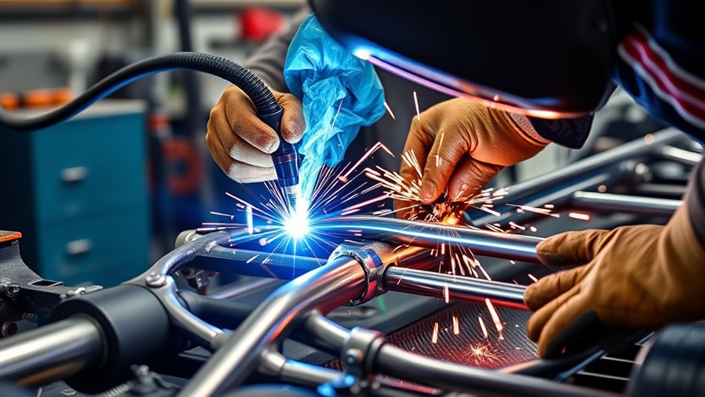
Mild-Steel Tabs, Brackets, and Panels
MIG or DCEN TIG can work well on weldable mild steel when the joint is clean, accessible, and permitted by the design. ER70S-6 wire in the .030- to .035-inch range is common for many shop MIG setups, but use the machine chart and test coupon to select the final wire size and settings.
Do not place a bracket where it creates a sharp stress concentration, blocks access to a required chassis weld, or loads a thin tube wall without suitable reinforcement. Match weld length and size to the drawing instead of making the largest bead that fits.
4130 Chromoly Roll-Cage and Chassis Tube
For critical 4130 tube, use the process, filler, fit-up, temperature controls, and inspection method required by the current rulebook or approved procedure. Many racing applications use TIG because it gives close control of the arc and filler, but process choice alone does not qualify the weld.
Do not assume every 4130 joint needs the same preheat or post-weld heat treatment. Tube thickness, normalized or heat-treated condition, filler choice, restraint, carbon equivalent, and procedure all matter. Ask the responsible chassis builder or welding engineer when these controls are not stated.
Aluminum Panels, Pipes, and Tanks
Remove oil and dirt before disturbing the oxide layer, then clean the joint with aluminum-dedicated tools. Keep filler rod and wire dry and protected from contamination. Choose 4043, 4943, or 5356 only after confirming the base alloy and operating conditions.
Use AC TIG when you need close control on thin work, or a suitable MIG setup when productivity and section thickness support it. Watch for poor cleaning action, oxide inclusions, lack of fusion, crater cracking, and excessive distortion.
Do not treat a fabricated fuel, oil, coolant, or pressure tank as an ordinary practice project. Leak testing, baffling, mounting, venting, alloy selection, fatigue, cleaning, and fire safety need a qualified design and procedure.
Stainless Exhaust Components
For compatible 304 stainless parts, ER308L is a common filler. Keep stainless preparation tools separate from carbon-steel tools. Use the required shielding and purge procedure where oxidation inside a tube would reduce corrosion resistance or obstruct flow.
Steering, Suspension, Brakes, Seats, and Restraints
Do not repair a control arm, spindle, steering arm, upright, wheel, spring, brake component, seat mount, harness anchor, or rollover structure by choosing DC TIG and assuming the part is safe. These components may be cast, forged, heat-treated, highly fatigued, or prohibited from repair.
Use the component manufacturer’s written repair procedure or an engineered motorsport procedure. When neither is available, replace the component or refer it to a qualified chassis fabricator or engineer. The same caution applies to unexplained cracks: find the load, alignment, design, or material problem before depositing a new bead over the symptom.
Control Heat, Weld Sequence, and Distortion
Heat control starts before the arc. Use accurate fit-up, enough restraint to hold alignment, and a sequence that balances shrinkage. Record critical dimensions so you can detect movement before it becomes permanent.
On thin sheet, use small tacks, alternate locations, and short controlled arc time. Move to a distant section while the first area cools. Keep travel speed steady and avoid dwelling at panel edges. A copper backing bar can support the puddle and help reduce burn-through where access and the joint design allow it.
Do not convert a specified continuous structural weld into scattered short sections merely to control distortion. If the drawing requires a continuous weld, use an approved sequence, fixture, balanced progression, or other procedure that still produces the required finished joint.
- Start with sound tacks that will be incorporated correctly into the finished weld.
- Balance welds across the component where the design allows.
- Allow natural cooling between sequences when the procedure permits it.
- Do not quench a hot structural weld with water or compressed air unless the approved procedure specifically allows it.
- Stop if fit-up opens, the puddle becomes uncontrollable, the gas shield is disturbed, or the part moves beyond tolerance.
Treat heat as a controlled input, not something to fight after the part has warped. Thin panels need low total heat and careful restraint; structural tube joints need complete fusion and the weld length required by the design.
Inspect Welds Before the Part Goes Back on the Car
Let the part cool and clean it without hiding the weld profile. Use good lighting, a mirror, and magnification where needed. Inspect the full circumference of tube joints rather than judging only the easy-to-see side.
- Confirm that the weld is in the correct location and has the specified length and size.
- Look for surface cracks, crater cracks, pinholes, porosity, undercut, overlap, arc strikes, and missed sections.
- Check that both toes blend into the base metal without an unfused edge.
- Inspect starts, stops, tie-ins, and tack-weld locations carefully.
- Check surrounding metal for melting, excessive thinning, distortion, or heat damage.
- Recheck dimensions, mounting points, suspension pickup locations, and component clearance.
- Confirm that wiring, lines, coatings, and nearby components were not damaged.
| Visible Condition | Why It Matters | Action |
|---|---|---|
| Crack in the weld or heat-affected zone | A crack can grow under vibration and cyclic loading. | Do not load the part. Determine the cause and use an approved repair or replace the component. |
| Porosity or pinholes | May indicate contamination, gas loss, moisture, or a leak in the shielding system. | Stop and correct the cause. Repair only under an acceptable procedure. |
| Undercut or melted tube edge | Reduces the effective base-metal section and can create a stress riser. | Have the joint evaluated before adding more weld metal. |
| Cold lap or poor toe tie-in | The bead may sit on the surface without complete fusion. | Reject and repair through an approved process; appearance alone cannot confirm penetration. |
| Severe distortion or moved pickup point | Can change alignment, handling, component preload, or driveline geometry. | Measure against the drawing or fixture and obtain an approved correction plan. |
Visual inspection can find many surface defects, but it cannot prove complete root fusion or reveal every internal crack. Critical joints may require dye penetrant, magnetic-particle, ultrasonic, radiographic, or another qualified nondestructive examination selected for the material and defect type. The American Welding Society’s discussion of weld cracks explains why different inspection methods are needed for surface and subsurface flaws.
Do not grind, sand, paint, powder-coat, or cover a critical weld before the required inspection. Some race rules prohibit grinding roll-cage welds because it can hide the original profile and defects. Retain material records, filler identification, procedure details, photographs, measurements, and inspection or chassis-certification documents when the class requires them.
Fix Warping, Weak Welds, and Burn-Through
Do not repair a defect until you understand why it occurred. Depositing another pass over contamination, a crack, or an unfused bead can trap the defect and add more heat.
| Problem | Likely Causes | Corrective Direction |
|---|---|---|
| Burn-through | Excess heat, slow travel, wide gap, wrong wire size, poor edge control, or thin material | Improve fit-up, reduce arc time, correct settings, increase travel speed where appropriate, and use copper backing if the procedure allows it. |
| Warping | Too much total heat, poor sequence, weak fixture, long uninterrupted sheet-metal welds | Improve restraint, balance the sequence, shorten sheet-metal arc time, and allow controlled cooling. |
| Porosity | Dirty metal, oil, moisture, wind, low or excessive gas flow, leaks, contaminated filler | Clean the joint, stop drafts, inspect the gas path, correct flow, and replace contaminated consumables. |
| Poor fusion or cold lap | Low heat at the joint, excessive travel speed, wrong torch angle, oxide or scale, poor access | Correct preparation and access, then validate heat and technique on a matching coupon before repairing the part. |
| Undercut | Excessive voltage or arc length, poor angle, fast travel, or failure to fill the toe | Correct the technique and settings. Have structural undercut evaluated before attempting repair. |
| Cracking | Wrong filler, unsuitable alloy, restraint, hydrogen or contamination, bad crater termination, or incorrect thermal procedure | Stop work, identify the material and crack mechanism, and obtain an approved repair or replace the part. |
Clean every joint because rust, paint, oxide, and oil can weaken the result. Fit parts to the specified seam rather than bridging an accidental wide gap with excess filler. If the puddle becomes uncontrollable, stop, let the component cool as permitted, inspect the setup, and make another matching coupon before returning to the part.
When cutting or trimming nearby material, follow suitable ventilation, fire-control, and PPE for plasma cutting. Cutting fumes, sparks, hot slag, hidden wiring, and fuel hazards remain present even when the welding machine is off.
When to Get Professional Help
Use a qualified welder, chassis fabricator, engineer, or inspector when the work affects steering, suspension, rollover protection, brakes, seat mounting, harness anchors, fuel containment, pressure systems, wheel retention, or another component whose failure could cause loss of control or injury.
Professional help is also appropriate when:
- The material, alloy, heat treatment, coating, or prior repair is unknown.
- The rulebook requires a certified chassis, approved process, specific filler, or named inspection.
- A crack has returned after an earlier repair.
- The joint has severe undercut, porosity, distortion, incomplete access, or suspected lack of fusion.
- The part is cast, forged, heat-treated, spring steel, or made from dissimilar metals.
- The weld is close to a fuel system, pressurized vessel, battery, pyrotechnic device, or high-voltage component.
- You cannot reproduce an acceptable result on a matching test coupon.
A qualified inspection can identify problems that a quick visual check may miss. Replacing a questionable component is often less costly than testing an unapproved repair under race conditions.
Frequently Asked Questions
What safety gear is essential for race car welding?
Wear a properly rated welding helmet, safety glasses with side protection, dry welding gloves, flame-resistant clothing, and leather footwear. Cover exposed skin. Add hearing, face, or respiratory protection when grinding, cutting, coatings, ventilation conditions, or the product instructions require it.
How do you ventilate a welding area properly?
Use local exhaust close to the welding plume so fumes are captured before they cross your breathing zone. Avoid airflow that removes shielding gas or sends fumes toward another person. Confined spaces and hazardous coatings require a specific ventilation and work-control plan.
Which welders are best for beginners?
MIG is often easier for a beginner to learn on clean mild steel because wire feeding and filler addition are combined. That does not make a beginner ready for a roll cage or suspension part. Learn joint preparation, machine setup, coupons, defect recognition, and fire safety before working on the car.
How do you inspect weld quality after finishing?
Check weld location, size, bead consistency, starts and stops, toe tie-in, undercut, cracks, porosity, arc strikes, distortion, and surrounding heat damage. Visual inspection cannot reveal every internal flaw, so critical joints may need qualified nondestructive testing and chassis certification.
What fire precautions should you take during welding?
Remove combustibles from the spark and heat path, inspect both sides of the work, shield vulnerable areas, keep a suitable extinguisher ready, and assign a fire watch when needed. Recheck concealed spaces after welding because seam sealer, insulation, and debris can smolder.
Can you MIG weld race car chromoly?
MIG may be used on some chromoly work under an approved procedure, but it is not universally permitted. Some current motorsport rules require approved TIG welding for 4130 or Docol roll-cage structures. Check the exact alloy, drawing, procedure, class rules, and inspection requirements before welding.
Should you disconnect the battery and electronics before welding?
Follow the vehicle manufacturer’s welding procedure. It may require disconnecting battery cables, disabling airbags, disconnecting nearby modules, shielding components, and placing the work clamp close to the joint. Hybrid and electric vehicles require trained high-voltage isolation and verification.
Can you grind race car roll-cage welds smooth?
Do not grind a roll-cage weld unless the governing drawing, rulebook, and inspector permit it. Grinding can reduce weld or tube thickness and hide the profile needed for inspection. Some racing regulations specifically prohibit grinding cage welds.
Safety Disclaimer: This article is for informational purposes only. It does not replace hands-on welding training, an approved welding procedure, vehicle manufacturer instructions, engineering review, occupational-safety requirements, race sanctioning rules, chassis certification, or professional inspection. Consult a qualified welder, chassis builder, engineer, or inspector before welding a load-bearing race car part.
Conclusion
Strong race car welding starts with the right process, verified material, compatible filler, clean fit-up, controlled heat, safe vehicle isolation, and an inspection plan. Before striking an arc, confirm the current rulebook, base alloy, joint design, machine setup, fuel and electrical hazards, and acceptance requirements.
Practice on scrap that matches the real material, thickness, joint, and position. Treat a neat-looking bead as the beginning of inspection—not proof of strength. When a weld affects steering, suspension, rollover protection, braking, seating, restraints, fuel containment, or another critical system, use a qualified procedure and professional oversight.
Sources
- Occupational Safety and Health Administration — Welding, Cutting, and Brazing Standards — ventilation, fire prevention, hot-work, and worker-safety requirements.
- General Motors — Electrical Best Practices — battery, airbag, module, grounding, wiring, and component-protection guidance during vehicle welding.
- Miller — Guide to TIG Welding Basics — common AC aluminum and DCEN steel TIG applications.
- Lincoln Electric — TIG Welding Chrome-Moly Tubing — 4130 process and filler considerations.
- Hobart Brothers — Aluminum Filler Metal Selection Guide — 4043, 4943, and 5356 selection limits.
- FIA — 2026 Drag Racing Sportsman Regulations — current examples of roll-cage process, weld-finish, inspection, and certification requirements.




