
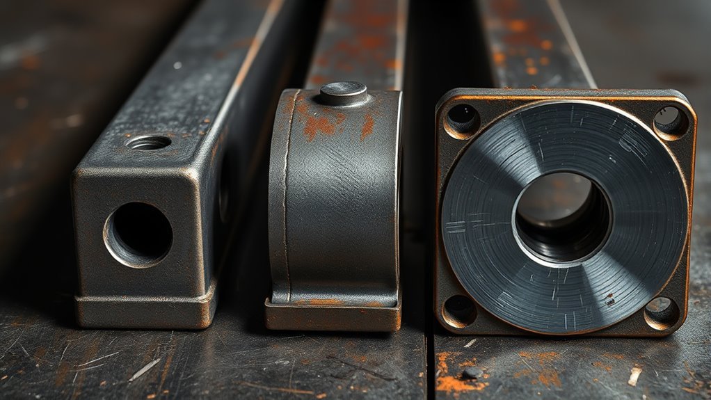
Butt joints, lap joints, and plug welds move force through metal in different ways. The best option depends on the direction of the load, material thickness, access, required finish, fatigue exposure, corrosion risk, and the welding code or drawing. A joint that looks heavy is not automatically strong, and a clean-looking weld is not proof of complete fusion.
Quick Answer
Choose a butt joint for an aligned, flush connection that may require a full-penetration groove weld. Choose a lap joint for overlapping sheet, simple fit-up, or loads carried mainly in shear. Use plug welds through holes in overlapping members when an edge weld is unavailable or the drawing specifically calls for them.
Key Takeaways
- Butt and lap describe how the parts fit together; a plug weld is a weld type used through a round hole in an overlapping member.
- A complete-joint-penetration butt weld can provide a direct load path, but only when the design, fusion, filler metal, and workmanship meet the requirement.
- Lap joints are easy to fit and useful for sheet metal, but their offset geometry can create bending and a moisture-trapping crevice.
- Plug-weld strength depends on the specified diameter, pitch, number, penetration, material thickness, edge distance, and weld quality.
- Do not select a joint from thickness alone. Follow the drawing, welding procedure specification, and applicable code for critical work.
What’s in This Article
- How Butt, Lap, and Plug Welds Differ
- Butt Joint Strength and Best Uses
- Where Lap Joints Add Strength
- Plug Weld Strength in Overlapping Joints
- How Thickness Changes Joint Strength
- Which Weld Joint Handles Stress Best?
- How to Choose the Right Weld Joint
- Quick Verdict
- Frequently Asked Questions
- Welding Safety Note
- Conclusion
- Sources
How Butt, Lap, and Plug Welds Differ
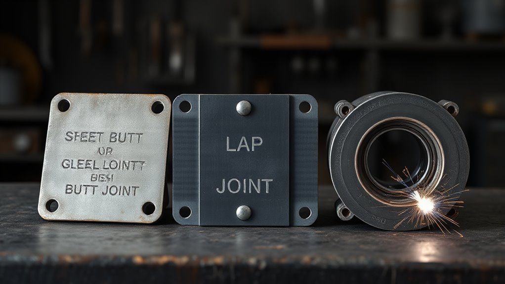
The first difference is terminology. A butt joint and a lap joint describe the position of the parts before welding. A plug weld describes weld metal placed in a round hole in one overlapping member so it fuses to the member beneath it.
The American Welding Society recognizes butt, corner, edge, lap, and T-joints as the five basic joint configurations. Butt joints commonly use groove welds. Lap joints commonly use fillet welds, but they may also use plug, slot, resistance spot, or other welds when the design permits. Miller’s joint-design guide explains these basic configurations.
Note: “Butt weld” is common shop language, but the more precise description is often a butt joint with a groove weld. Keeping joint geometry and weld type separate makes drawings, symbols, and inspection requirements easier to understand.
| Option | What it describes | Typical arrangement | Common weld | Main limitation |
|---|---|---|---|---|
| Butt joint | Joint geometry | Edges meet in the same plane | Square, V, bevel, U, J, or other groove weld | Fit-up, root access, and edge preparation may be demanding |
| Lap joint | Joint geometry | One member overlaps another | Fillet, plug, slot, or resistance spot weld | Offset loading can cause bending; the overlap may trap moisture |
| Plug weld | Weld type | A round hole in the upper overlapping member is welded to the member below | Weld metal deposited in the specified hole | Localized load transfer and difficult confirmation of fusion at the bottom member |
All three options depend on accurate fit-up, clean metal, correct parameters, and enough access to place and inspect the weld. Poor preparation can cause incomplete fusion, porosity, burn-through, undercut, distortion, or a load path that does not match the design.
The welding process changes how easily the joint can be made, but it does not make one geometry automatically stronger. MIG can offer speed, TIG can provide precise arc and heat control, and stick or flux-cored welding may suit thicker material and field conditions. For an example of TIG heat control, see these TIG welder settings for stainless steel.
The strongest connection is the one whose geometry, weld size, penetration, filler metal, and workmanship match the actual load—not simply the joint with the strongest reputation.
Butt Joint Strength and Best Uses
A butt joint places two members in the same plane. This aligned geometry can create a direct load path with less offset bending than a one-sided lap joint. It also produces a flush profile when the finished weld is ground or formed to match the base material.
Butt joints are common in plate, pipe, tubing, tanks, frames, machinery, vehicle panels, and other work where edge-to-edge alignment is useful. Their final strength depends on the groove design, effective weld size, fusion, filler metal, base-metal properties, defects, and service load.
Complete vs Partial Joint Penetration
A complete-joint-penetration weld, or CJP weld, has weld metal and fusion through the full thickness of the joint as required by the design. A partial-joint-penetration weld, or PJP weld, has a specified effective depth that is less than the full joint thickness.
CJP does not mean that any weld bead visible on the back is automatically acceptable. The joint still needs complete fusion, suitable filler metal, proper root geometry, and any inspection required by the specification. Lincoln Electric’s explanation of fusion versus penetration shows why penetration depth alone does not prove weld quality.
Square edges may be suitable when the process, material thickness, access, and required penetration allow them. Other joints use V, bevel, U, J, or double-sided preparations to reach the required effective weld size while controlling deposited weld metal and distortion.
Note: Do not choose a bevel angle, root opening, root face, backing method, or groove depth from a general article. Use the drawing, approved welding procedure specification, material requirements, and applicable code.
Correct amperage and voltage help establish a stable arc and proper fusion, but settings must match the electrode, wire, shielding gas, position, joint, and machine. This guide to matching stick-welding amperage to metal thickness explains one part of that setup.
| Application | Why a butt joint may fit | Important condition |
|---|---|---|
| Structural plate splices | Maintains an aligned load path and can be designed as a CJP or PJP groove weld | Must follow the engineer’s detail, WPS, code, and inspection plan |
| Pipe and tubing | Provides a continuous circumference and can leave a smooth internal or external profile | Root quality, alignment, process qualification, and service requirements are critical |
| Sheet-metal panels | Creates a flush seam without an overlapping edge | Tight fit-up and careful heat sequencing are needed to limit burn-through and warping |
| Heavy machinery | Can transfer force directly through thick, aligned members | Fatigue, impact, restraint, preheat, filler metal, and inspection must be addressed |
A butt joint is a strong candidate when the members must remain in one plane, a flush surface matters, or the design calls for a groove weld with a known effective depth. It is less attractive when root access is poor, fit-up cannot be controlled, edge preparation is impractical, or distortion would be difficult to manage.
Where Lap Joints Add Strength
A lap joint places one member over another and usually joins the exposed edge of the upper member to the face of the lower member with a fillet weld. The overlap can simplify fit-up and provide more room for attaching thin sheet or materials of different thicknesses.
Lap joints often work well when the design carries force mainly through shear in the weld. They can also be welded from both sides when both edges are accessible and the drawing permits it. Welding both sides may improve rigidity and balance the connection, but it also adds heat, time, and weld metal.
Overlapping Load Distribution and Offset Bending
The overlap provides more contact area than an edge-to-edge seam, but the contact area itself does not determine weld strength. Force still has to pass through the specified fillet, plug, slot, spot, or other weld.
A one-sided lap joint has an offset load path because the centers of the two members do not line up. That offset can rotate or bend the joint under tension. The designer must consider this secondary bending instead of assuming that more overlap always means more strength.
Good overlap, close contact, clean faying surfaces, correct weld size, and sound welding parameters improve consistency. Excessive gaps can change the effective weld shape and increase the chance of incomplete fusion or distortion.
Thin Material Advantages
Lap joints are common in sheet metal because they are easier to fit than a perfectly aligned open seam. The overlap can also tolerate heat better than an unsupported butt-joint edge in some applications.
There is no universal rule that lap joints belong below one thickness and butt joints belong above it. Thin sheet can use either geometry, and thick plate can use lap-type connections when an engineered design calls for them. The decision depends on load, overlap, weld size, process capacity, access, finish, weight, and service conditions.
When welding thin material, tight fit-up and controlled heat help reduce burn-through and warping. Short weld segments, balanced sequencing, clamps, fixtures, and a suitable backing or chill bar may help, depending on the material and procedure.
Pro Tip: Clean both overlapping faces before assembly. Paint, oil, rust, mill scale, moisture, adhesive, and plating trapped in the joint can contaminate the weld or release hazardous fumes when heated.
Lap-Joint Corrosion and Fatigue
The narrow gap between overlapping members can hold water, road salt, or chemicals. A suitable coating, seal, drainage path, or closed detail may be needed after welding. Do not seal over contamination or use an unapproved sealant close to a weld that has not cooled.
Repeated loading can also start cracks at weld toes, ends, undercut, lack of fusion, or other sharp transitions. A joint that performs well under one static pull may not have the same margin under years of vibration or load reversal.
Plug Weld Strength in Overlapping Joints
A plug weld joins overlapping members. A round hole is drilled, punched, or otherwise prepared in the upper member, and weld metal is deposited in the hole so it fuses to the exposed surface of the member below and to the hole wall as required.
A standard T-joint is different: one member meets the face of another at about 90 degrees and is commonly joined with a fillet or groove weld. A larger assembly may contain both T-shaped geometry and an overlapping attachment, but the plug weld itself is made through the overlap.
Plug welds can provide strong localized attachment where an exposed edge is unavailable, where a drawing calls for attachment at selected points, or where sheet-metal work is replacing factory spot-weld locations. They should not automatically replace a continuous fillet weld, groove weld, fastener, or engineered connection.
The welding symbol may specify the plug diameter, pitch or center-to-center spacing, quantity, side containing the holes, and fill depth. Miller’s guide to plug and slot weld symbols illustrates these dimensions.
What Controls Plug-Weld Strength?
- Hole diameter: Affects available fusion area, heat input, and the welder’s ability to reach the lower member.
- Number and pitch: Determine how load is shared among the welds and whether the members between holes can carry the force.
- Edge distance: Too little material around a hole can allow tearing or distortion.
- Material thickness: Changes the heat needed to fuse the lower member without excessively melting the upper hole edge.
- Penetration and fusion: The bead must fuse where the design requires it, especially at the bottom member and hole wall.
- Fill depth: Some drawings require the hole to be filled flush; others may specify a different depth.
- Load direction: Plug welds commonly transfer localized shear, but the full connection must also resist peeling, prying, bending, and fatigue where present.
- Inspection access: The top surface may look filled even when fusion to the lower member is incomplete.
A filled hole is not proof of a sound plug weld. The connection depends on fusion to the lower member, fusion around the required hole wall, and dimensions that match the drawing or procedure.
Plug vs Slot, Spot, and Rosette Welds
A slot weld uses an elongated opening rather than a round hole. The longer opening may provide more weld length or suit a different load arrangement, but it is not automatically stronger. Its width, length, pitch, effective area, and surrounding base metal must be designed.
A resistance spot weld is made by clamping overlapping sheet between electrodes and passing current through the contact area. It does not require a drilled plug hole. In informal automotive language, “rosette weld” is often used for a circular plug weld, but drawings and inspection records should use the terminology required by the governing standard.
When galvanized steel is involved, identify the coating and follow the approved procedure before heating it. Removing zinc only from the immediate weld area does not eliminate the need for ventilation or respiratory-hazard controls. This guide explains common methods for removing zinc coating from galvanized steel.
Warning: Heating galvanized steel can produce zinc oxide fumes associated with metal fume fever. Use effective local exhaust or other ventilation required by the job, keep your head out of the plume, and follow the safety data sheet, employer program, and applicable respiratory-protection rules.
How Thickness Changes Joint Strength
Material thickness affects the required weld size, heat input, number of passes, edge preparation, distortion, preheat, cooling rate, and inspection. It does not create a universal dividing line between butt, lap, and plug connections.
Thin vs Thick Materials
Thin material heats quickly and offers little metal to absorb the arc. Loose fit-up, a wide root gap, slow travel, oversized wire, excessive amperage, or a long arc can cause burn-through and warping. Tight fit-up and a heat-control plan are especially important. Miller’s sheet-metal welding guidance explains why small gaps and concentrated heat create problems.
Thicker material may require more energy, multiple passes, joint preparation, preheat, or a higher-capacity process. It can also create greater restraint and residual stress. The required approach depends on the alloy, thickness combination, hydrogen control, welding position, service temperature, and approved procedure.
When joining different thicknesses, direct more heat toward the thicker member while still achieving fusion at the thinner edge. The exact torch or gun angle, travel speed, and parameters depend on the process and procedure.
Penetration Needs by Thickness
A butt joint may use a square groove, root opening, bevel, V-groove, J-groove, U-groove, backing, back gouging, or double-sided preparation. The required effective depth must come from the drawing or welding procedure—not a general 6 mm or 10 mm threshold.
Lap joints also need a weld sized for the actual force. Adding a larger fillet weld does not always add useful capacity because the base metal, overlap, heat-affected zone, or connection geometry may control first. Review the applicable design rules before selecting a maximum fillet weld size for the plate thickness.
Plug welds need enough access and heat to fuse the lower member without washing away the top hole edge or trapping slag and gas. Hole size and spacing must come from the design, repair procedure, manufacturer instruction, or applicable code.
Note: Preheat and interpass-temperature requirements are material- and procedure-specific. Do not apply a generic temperature from another steel grade, thickness, or welding process.
Which Weld Joint Handles Stress Best?
No joint is strongest under every type of stress. Static tension, compression, shear, bending, impact, vibration, fatigue, and stress reversal affect welded connections differently.
An aligned butt joint with a properly designed CJP groove weld often provides the cleanest path for axial force because the members remain in the same plane. A PJP butt joint may also be entirely suitable when its effective weld size is designed for the load.
A lap joint can perform efficiently when the weld carries shear, but a one-sided connection may rotate because the member centerlines are offset. Welding both accessible sides can change the load path, but it must be part of the design rather than an unplanned addition.
A plug weld transfers force through localized fused areas. It can reinforce an overlap or replace selected attachment points, but it does not distribute force in the same way as a continuous groove or fillet weld.
| Connection | Often performs well when | Watch for |
|---|---|---|
| CJP butt joint | Aligned members must carry axial force through the full joint thickness | Root defects, lack of fusion, filler mismatch, poor profile, high restraint, and required NDT |
| PJP butt joint | The designed effective weld size is sufficient without full penetration | Assuming full-thickness capacity when the effective throat is smaller |
| Lap joint with fillet welds | Overlap simplifies fit-up and the weld is sized for the applied shear and bending | Eccentric loading, peeling, crevice corrosion, weld-end cracking, and excess heat |
| Plug-welded overlap | The drawing requires localized attachment through the upper member | Incomplete fusion to the lower member, poor hole dimensions, tearing, and fatigue |
Fatigue and Repeated Loading
Fatigue cracks often begin at a discontinuity or sharp change in shape. Weld toes, starts and stops, undercut, craters, incomplete fusion, attachments, holes, and abrupt changes in stiffness can all matter. More weld metal is not a universal fatigue cure.
Connections exposed to vibration, impact, vehicle loads, lifting cycles, pressure changes, or stress reversal need a detail approved for that service. Use the applicable calculation method, code category, and inspection plan rather than ranking joints from appearance alone. This overview of how to calculate welded-joint strength explains the basic design inputs.
Inspection and Weld Quality
Visual inspection can identify surface cracks, overlap, undercut, incomplete fill, poor contour, arc strikes, excessive spatter, and dimensional problems. It cannot prove that an internal groove weld has full fusion or that a plug weld has fused correctly to the lower member.
Critical welds may require magnetic-particle, liquid-penetrant, ultrasonic, radiographic, or another examination method. The process, extent, acceptance criteria, and inspector qualifications come from the governing specification. FHWA notes that internal discontinuities such as lack of fusion can act as fatigue-crack initiation sites and may not be visible at the surface.
How to Choose the Right Weld Joint
Choose the joint by working through the design requirements in order. Do not start with the process you prefer or the joint that is easiest to tack together.
- Identify the governing document. Check the engineering drawing, repair manual, manufacturer instruction, welding procedure specification, and adopted code.
- Define the loads. Note tension, compression, shear, bending, impact, vibration, fatigue, peeling, and stress reversal.
- Check the required load path. Decide whether the members should remain aligned or whether an overlap is acceptable.
- Review the materials. Confirm alloy, coating, condition, thickness combination, weldability, filler metal, and any preheat or hydrogen-control requirements.
- Check access and position. Determine whether both sides, the root, the back of the joint, and the finished weld can be reached and inspected.
- Consider distortion and finish. A flush butt joint may suit a visible surface, while a lap joint may be faster but bulkier and more likely to trap moisture.
- Confirm inspection and service requirements. Pressure, lifting, vehicle-safety, structural, fatigue-sensitive, and life-safety work may require qualified procedures, welders, documentation, and nondestructive testing.
Products Worth Considering

🎲Superior Processing: Our steel plates are all laser-cut, providing edge and overall flatness that is unmatched by other stamped and sheared components.

Fun and Functional Cat Design: turn practice into art! This welding practice kit lets you craft a charming 3D cat sculpture; Once completed, it serves as an ideal desk decor piece or handmade gift, ideal for Father's Day, birthdays, and holiday gifting for welding enthusiasts and cat lovers alike

79pieces TIG Torch Accessories (consumables).
Choose a Butt Joint When
- The members need to remain in the same plane.
- A flush contour or continuous seam matters.
- The drawing calls for a CJP or PJP groove weld.
- Both the root design and required inspection can be controlled.
- The aligned load path provides a design advantage.
Choose a Lap Joint When
- Overlapping sheet or plate is acceptable.
- Simple fit-up is more important than a flush surface.
- The fillet, plug, slot, or spot weld can be sized and accessed correctly.
- The design accounts for eccentric bending and any moisture-trapping crevice.
- The overlap does not create an unacceptable weight, clearance, or finishing problem.
Choose a Plug Weld When
- The connection consists of overlapping members.
- An exposed edge weld is unavailable or unsuitable.
- The drawing or approved repair procedure specifies plug locations and dimensions.
- The hole provides enough access to fuse the lower member.
- The completed weld can be inspected to the required level.
Fit-Up and Preparation Checklist
- Remove rust, oil, paint, moisture, mill scale, plating, and other contamination as required by the procedure.
- Confirm joint angle, overlap, root opening, root face, alignment, hole diameter, pitch, and edge distance.
- Use clamps, fixtures, strongbacks, or tack welds that hold alignment without blocking required access.
- Check the machine capacity, polarity, electrode or wire, shielding gas, and approved parameter range.
- Plan the welding sequence to limit shrinkage and distortion.
- Confirm that coatings, sealants, cleaners, and nearby materials will not create toxic fumes or a fire hazard.
- Inspect each pass when the procedure requires it and remove slag before covering the pass.
Welder output still needs to match the material and process. This guide to choosing a welder for 1/4-inch steel can help with machine capacity, but it does not replace an approved joint design or procedure.
Note: Current AWS standards cover different materials and industries. Use the standard and edition adopted by the project, contract, manufacturer, or authority having jurisdiction. Do not assume that a rule from structural steel also applies to a pressure vessel, bridge, pipeline, aluminum assembly, or vehicle repair.
Quick Verdict: Butt vs Lap vs Plug Welds
Choose a butt joint when you need an aligned connection, a flush profile, or a specified groove weld. A properly designed CJP butt joint can carry force through the full joint thickness, but complete fusion and correct filler metal remain essential.
Choose a lap joint when overlap simplifies fit-up or suits sheet-metal fabrication. It can perform well in shear, but the offset geometry, corrosion crevice, weld size, and access must be addressed.
Choose a plug weld only for overlapping members when the drawing, repair method, or connection design calls for attachment through round holes. Control the diameter, pitch, number, edge distance, fill depth, and fusion to the lower member.
| Option | Choose it if | Be careful when |
|---|---|---|
| Butt joint | You need aligned members, a flush seam, or a specified groove weld | Fit-up, root access, edge preparation, distortion, or internal inspection is difficult |
| Lap joint | Overlap simplifies fabrication and the connection is designed for its shear and bending | Repeated bending, peeling, corrosion, hidden contamination, or a flush finish is a concern |
| Plug weld | You need localized attachment through a hole in an overlapping member | Hole dimensions, spacing, fusion, edge distance, load direction, or inspection is not controlled |
Products Worth Considering

Value Pack: The package includes 24 packs of butt welding clamps, enough quantity to meet your daily needs and replacements. Each butt welding clamps is individually wrapped in a small bag, convenient to carry and use.

16-Pack Welding Clamps Set: Includes 16 butt welding clamps designed for precise edge-to-edge welding, ideal for body repair, floor patching, door skins, and sheet metal alignment.

Butt Clamps Specification:Each welding square tool pipe clamp can extend the clamp block to provide a .4-inch (1cm) tall gap; Fits 3/16-inch to 26 gauge sheet metal materials
Frequently Asked Questions
Are slot welds stronger than plug welds?
Not automatically. A slot may provide more weld length than a round plug, but capacity depends on the specified width, length, pitch, effective weld area, base-metal strength, edge distance, fusion, and load direction. Use the connection design rather than the opening shape alone.
What are the disadvantages of plug welds?
Plug welds require accurate hole dimensions, clean contact surfaces, good access, and enough heat to fuse the lower member. A filled top surface can hide incomplete fusion below. Plug welds also transfer load at separate points and may be restricted in some engineered or fatigue-sensitive applications.
What are the disadvantages of using a lap joint?
A lap joint adds thickness and weight, leaves a visible step, and can trap moisture or contamination between the members. Its offset load path may also cause rotation, peeling, or secondary bending under tension and repeated loading.
What corner joint is the strongest?
There is no universally strongest corner joint. Open and closed corner details can use fillet or groove welds, and their capacity depends on the load direction, material, effective weld size, penetration, access, distortion, and workmanship. Use the detail specified by the design.
Is a butt weld always stronger than a lap weld?
No. A sound lap joint designed for its load can outperform a defective or undersized butt-joint weld. A CJP butt joint often offers an efficient aligned load path, but strength still depends on the weld design, base metal, filler metal, fusion, defects, and service conditions.
Can a plug weld replace a factory spot weld?
Sometimes an approved vehicle or equipment repair procedure uses plug welds where factory resistance spot welds cannot be reproduced. That does not make them interchangeable in every repair. Follow the manufacturer’s location, hole-size, spacing, material, corrosion-protection, and welding instructions.
What does full penetration mean in a butt joint?
In a complete-joint-penetration groove weld, the required weld extends through the joint thickness and achieves fusion as specified by the design. A visible root bead alone does not prove acceptable CJP quality; the joint must also meet the required procedure and inspection criteria.
Welding Safety Note
Warning: Welding can expose you to electric shock, ultraviolet and infrared radiation, hot metal, sparks, fire, compressed gas, noise, and hazardous fumes. Wear a suitable welding helmet, safety glasses, flame-resistant clothing, gloves, and other PPE required for the job. Remove combustibles, provide fire protection, inspect leads and equipment, and use adequate ventilation.
Identify the base metal, coatings, cleaners, paint, plating, and nearby materials before welding. Galvanized, stainless, painted, cadmium-coated, lead-coated, or solvent-contaminated materials can create added hazards. Never weld on a closed container, tank, drum, fuel system, or unknown vessel unless it has been properly cleaned, tested, vented, and released under an approved procedure.
Confined-space welding requires specific atmospheric testing, ventilation, attendant, rescue, and respiratory-protection controls. General shop airflow is not a substitute for a hazard assessment or local exhaust when fumes collect in the breathing zone. Review OSHA’s welding, cutting, and brazing requirements and the safety data sheets for the materials and consumables being used.
Safety Disclaimer: This article is for informational purposes only and does not replace professional welding training, engineering, an approved welding procedure, manufacturer repair instructions, code requirements, or workplace safety rules. Consult a qualified welding professional, engineer, or inspector before using any weld joint in a critical structure, pressure system, lifting device, vehicle-safety component, or fatigue-sensitive assembly.
Conclusion
A butt joint offers an aligned, potentially flush connection and may use a CJP or PJP groove weld. A lap joint simplifies overlap and sheet-metal fit-up but can introduce offset bending and corrosion traps. A plug weld provides localized attachment through a round hole in an overlapping member; it is not a separate basic joint configuration or a standard substitute for a T-joint weld.
Choose the connection from the required load path, material, access, finish, fatigue exposure, corrosion environment, drawing, WPS, and governing code. Careful fit-up, suitable heat input, complete fusion, qualified workmanship, and the required inspection matter more than the joint’s name.
Sources
- Miller Electric — A Guide to the Five Basic Types of Weld Joints — backs the definitions, geometry, fit-up, and common uses of butt, lap, and T-joints.
- Miller Electric — How to Read and Understand Weld Symbols — backs groove, fillet, plug, and slot-weld terminology and symbol dimensions.
- Lincoln Electric — Weld Fusion vs Weld Penetration — backs the distinction between penetration depth, complete fusion, filler metal, and CJP weld strength.
- American Welding Society — Codes and Standards — provides current code context and explains why engineered welding details must follow the applicable standard.
- OSHA — 29 CFR 1910.252, Welding, Cutting, and Brazing — backs ventilation, fume, equipment, and workplace safety requirements.
- Federal Highway Administration — Weld Inspection Research — backs the discussion of internal discontinuities, fatigue-crack initiation, and nondestructive examination.




