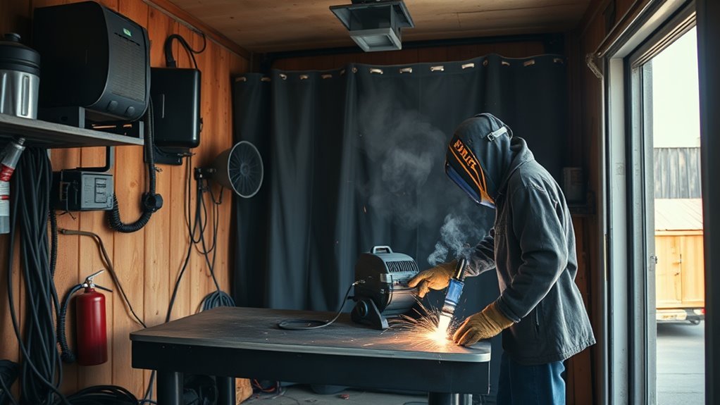
ER70S-6 is a common solid MIG wire for mild-steel auto body repair because it combines a 70 ksi-class weld deposit with higher silicon and manganese deoxidizer levels than ER70S-3. It runs smoothly on thin sheet, patch panels, brackets, and general shop repairs, but it is not suitable for every vehicle panel or every OEM repair procedure.
Quick Answer
ER70S-6 is a strong starting wire for approved mild-steel auto body repairs because its silicon and manganese help manage light oxidation after proper cleaning. For thin sheet, use 0.023- or 0.024-inch wire, DCEP polarity, C25 shielding gas, and short, spaced tacks. Always follow the vehicle maker’s repair procedure.
Key Takeaways
- ER70S-6 is a solid carbon-steel electrode or rod classified under AWS A5.18/A5.18M:2021.
- The “70” identifies the 70 ksi tensile-strength class, “S” means solid wire, and “6” identifies its chemical-composition classification.
- For light-gauge body panels, 0.023- or 0.024-inch wire and 75% argon/25% CO2 are practical starting choices.
- Solid ER70S-6 normally runs on direct-current electrode positive, or DCEP.
- The wire offers more deoxidizing action than ER70S-3, but it does not make paint, oil, zinc, rust scale, undercoating, or seam sealer safe to weld through.
- Do not weld structural, high-strength, ultra-high-strength, hybrid, or EV components until you have verified the exact OEM procedure for the VIN and model year.
At a Glance
| Time Required | About 30–60 minutes for preparation, machine setup, and test coupons; the actual repair time depends on panel size, access, fit-up, and the OEM procedure. |
| Difficulty | Intermediate. Thin sheet requires accurate fit-up, low-heat machine control, safe vehicle preparation, and patient tack sequencing. |
| Tools Needed | Low-output-capable MIG welder, ER70S-6 wire, C25 gas and flowmeter, correct V-groove drive roll and contact tip, clamps, sheet-metal tools, grinder, PPE, ventilation, fire extinguisher, and matching scrap. |
| Cost | Consumable cost is modest if you already own the welder, gas cylinder, PPE, and body tools. A complete first-time setup costs substantially more and varies by equipment. |
Warning: Welding creates fire, fume, UV, burn, and electric-shock hazards. Verify the OEM depowering procedure before disconnecting batteries or electronic equipment. Identify fuel lines, tanks, airbags, pretensioners, wiring, modules, adhesives, foam, sound deadener, and combustible trim on both sides of the panel. Hybrid and electric vehicles require model-specific high-voltage isolation by a qualified person. Use ventilation, suitable PPE, an extinguisher, and a fire watch where required.
What Makes ER70S-6 a Common Auto Body MIG Wire?
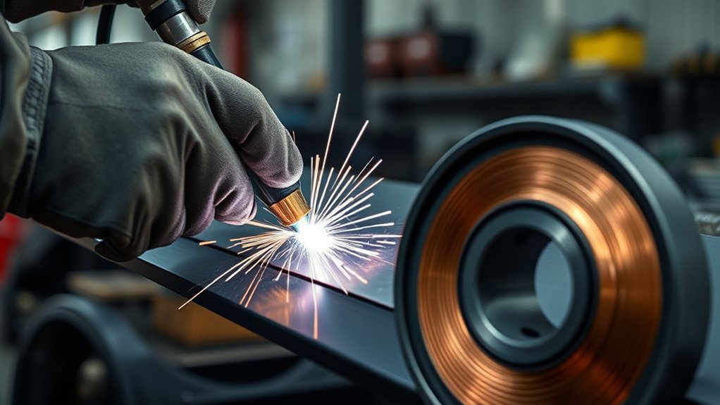
ER70S-6 is widely used in automotive and general fabrication because it produces a strong mild-steel weld deposit and has enough deoxidizing alloy to manage small amounts of oxygen from light mill scale or surface oxidation. That gives the puddle a useful working margin after the joint has been cleaned.
The wire suits approved repairs on mild-steel patch panels, floor sections, brackets, tabs, and non-critical sheet-metal seams. Its smooth short-circuit arc also makes it easier to place small tacks in awkward areas such as wheel openings, floor pans, and the underside of a vehicle.
ER70S-6 is not the correct filler for every vehicle part. Modern vehicles may use mild steel, high-strength steel, ultra-high-strength steel, stainless steel, aluminum, galvanized panels, structural adhesives, rivets, MIG brazing, or OEM-specific welding methods. Before repairing a structural part, identify the exact vehicle, model year, panel material, joint, and required joining procedure in the manufacturer’s repair information.
| Best use | OEM-approved GMAW repairs on mild-steel body panels, patch work, brackets, tabs, and general shop fabrication |
| Main advantage | Higher silicon and manganese deoxidizer levels than ER70S-3 |
| Main limit | It does not replace sound metal, proper cleaning, correct filler selection, ventilation, PPE, or the OEM repair procedure |
If you switch between mild steel and stainless wire, keep stainless consumables and abrasives separate from carbon-steel contamination. A dedicated stainless liner, brush, contact tip, and grinding media help prevent carbon-steel particles from becoming embedded in stainless work.
What Does ER70S-6 Mean?
ER70S-6 is a classification, not a statement that the wire is automatically correct for every 70 ksi steel or automotive panel. Under AWS A5.18/A5.18M:2021, the designation identifies the filler-metal form, tensile-strength class, solid construction, and chemical-composition category.
| Marking | Meaning | Practical Importance |
|---|---|---|
| ER | Electrode or rod | The classification may be supplied as continuously fed electrode wire or filler rod |
| 70 | 70 ksi tensile-strength class | The classified weld metal meets the specification’s minimum tensile requirement under its test conditions |
| S | Solid wire | It requires external shielding gas when used for GMAW |
| 6 | Chemical-composition classification | This category has relatively high manganese and silicon deoxidizer levels |
Note: The 70 ksi classification does not prove that a finished automotive joint matches the original panel strength. Joint design, panel metallurgy, heat input, fit-up, weld location, and the OEM repair method all affect the completed repair.
ER70S-6 Chemistry and Deoxidizers
ER70S-6 contains silicon and manganese that act as deoxidizers in the weld puddle. The Hobart HB-28 ER70S-6 datasheet lists AWS composition ranges of 1.40–1.85% manganese and 0.80–1.15% silicon. Those elements react with oxygen and help the molten weld metal flow and tie into the joint.
This chemistry gives you a wider working window on steel with light mill scale or minor oxidation after preparation. It does not make it acceptable to weld through paint, thick rust, grease, adhesive, seam sealer, body filler, undercoating, zinc coating, or trapped moisture.
Think of ER70S-6 as having extra deoxidizing margin, not as a substitute for bright, dry, structurally sound metal.
In practical shop terms, ER70S-6 is a gas-shielded solid carbon-steel filler wire. It is not self-shielded flux-core wire. If you are comparing it with outdoor options, a wire such as Lincoln Electric NR-211 flux-core wire solves a different problem. Self-shielded flux-core is less vulnerable to wind, while ER70S-6 with shielding gas normally gives you a cleaner bead and less slag indoors.
Silicon Islands and Paint Preparation
The same silicon that improves deoxidation can leave small glassy deposits, often called silicon islands, on the weld surface or along the bead toes. These deposits are not the same as heavy flux slag, but they should be removed before primer, paint, plating, adhesive, seam sealer, or other surface conditioning.
Use a clean abrasive, wire brush, or suitable surface-preparation method without thinning the surrounding panel. Inspect the bead again after cleaning so a silicon deposit is not mistaken for a pinhole or hidden weld defect.
ER70S-6 Versus ER70S-3
ER70S-6 is usually the more forgiving choice when properly prepared mild steel retains light mill scale or minor oxidation. ER70S-3 is better suited to clean steel and can leave fewer silicon deposits, which may reduce cleanup before painting or plating.
| Feature | ER70S-6 | ER70S-3 |
|---|---|---|
| Deoxidizer level | Higher silicon and manganese | Lower than ER70S-6 |
| Surface condition | More margin on lightly oxidized or scaled steel after prep | Best on consistently clean steel |
| Silicon deposits | More likely and must be cleaned before coating | Usually fewer deposits on clean steel |
| Typical auto body use | Common general repair choice | Useful for clean sheet where low post-weld cleanup is important |
Choose ER70S-6 when the OEM procedure permits solid-wire GMAW and you want the added deoxidizing margin. Choose ER70S-3 when the steel is consistently clean and its lower silicon-deposit tendency better suits the finishing process. If wind prevents reliable shielding-gas coverage, review these flux-core welding tips rather than forcing gas-shielded MIG into an uncontrolled outdoor environment.
Products Worth Considering

Commonly used for general shop applications with poor fit-up

Commonly used for general shop applications with poor fit-up.

Top Brand Welding Wire: Blue Demon ER70S-6 welding wire is formulated to provide porosity-free, x-ray quality welds, ensuring a strong and long-lasting bond
Where You Should Not Use ER70S-6
Do not select ER70S-6 only because the part is magnetic or looks like ordinary steel. Vehicle makers use several grades and joining methods, and applying conventional MIG heat in the wrong location can reduce crash performance or damage coatings, adhesives, electronics, and nearby components.
- Aluminum panels: Use the OEM-specified aluminum filler, process, equipment, and contamination controls.
- Stainless steel: Use a stainless filler selected for the exact base metal and service requirement.
- Cast iron or cast steel: Identify the casting and use an approved repair procedure and filler.
- High-strength and ultra-high-strength steel: Do not weld unless the OEM procedure allows that process, location, joint, filler, and heat input.
- MIG-brazed joints: Do not replace silicon-bronze MIG brazing with ER70S-6 fusion welding unless the manufacturer specifically permits it.
- Rivet-bonded or adhesive-bonded joints: Follow the specified rivet, adhesive, weld, surface-preparation, and curing procedure.
- Suspension, steering, restraint, or high-voltage parts: Use only the manufacturer-approved repair or replacement method.
Warning: A structural repair procedure should be checked against the vehicle’s VIN, model year, body style, panel location, and available OEM repair information. A method approved for one model year or joint may be prohibited on another.
Best Shielding Gas for ER70S-6
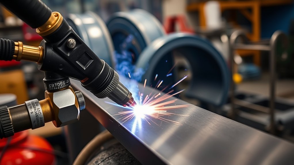
For most thin mild-steel body work, start with 75% argon and 25% CO2, commonly called C25. This blend supports stable short-circuit transfer, produces less spatter than straight CO2, and makes heat easier to control on light-gauge sheet.
For a small indoor MIG gun, approximately 20–25 CFH is a common starting flow. Set the flow while gas is moving through the gun, then follow the welder, gun, regulator, and wire manufacturer’s instructions. Some products, larger nozzles, or high-output applications specify more flow.
Do not raise the flow automatically when porosity appears. Excessive flow can create turbulence and draw surrounding air into the shielding zone. Drafts, leaks, a dirty nozzle, poor gun angle, excessive contact-tip-to-work distance, or contamination may be the real cause.
| Gas | Best For | Tradeoff |
|---|---|---|
| 75/25 argon-CO2 | Short-circuit welding on thin mild-steel panels | Higher cylinder cost than straight CO2 |
| 100% CO2 | Greater penetration and lower shielding-gas cost | Hotter arc feel, more spatter, and rougher bead appearance |
| 90/10 argon-CO2 | Low-spatter shop work when approved by the wire and procedure | Do not use high-current spray transfer on thin body panels merely because the gas can support it |
Pro Tip: Check shielding flow with the trigger held and the wire feed disabled when your machine allows it. A flowmeter reading taken with no gas moving may not represent the actual flow at the nozzle.
Galvanized automotive sheet requires additional coating-removal, fume-control, corrosion-restoration, and OEM-procedure precautions. Review this guide to MIG welding galvanized steel before working near zinc-coated areas.
Products Worth Considering
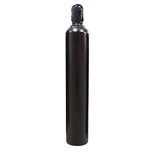
All HP cylinders come with a 10 year hydrotest date stamped.

All HP cylinders come with a 10 year hydrotest date stamped.

All HP cylinders come with a 10 year hydrotest date stamped.
Machine Setup for ER70S-6
Good results depend on more than voltage and wire speed. Match the complete feed path and polarity to the solid-wire setup before testing on sheet metal.
- Confirm polarity: Solid ER70S-6 normally uses DCEP, meaning the gun is connected to positive and the work lead is connected to negative.
- Install the correct drive roll: Use a smooth V-groove roll sized for the wire. Knurled rolls can shave solid wire and contaminate the liner.
- Match the liner and contact tip: The liner and tip must suit 0.023/0.024-, 0.030-, or 0.035-inch wire.
- Set spool tension: Use enough brake tension to prevent overrun without making the drive motor fight the spool.
- Set drive-roll pressure: Use only enough pressure for reliable feeding. Excess pressure can deform the wire or accelerate liner wear.
- Clean the nozzle and diffuser: Spatter buildup can disturb gas flow or electrically short the nozzle.
- Attach the work clamp correctly: Clamp to clean, bare metal as close to the weld area as practical without interfering with the repair.
- Keep the gun cable straight: Tight coils and sharp bends increase feeding resistance, especially with small wire.
Note: Store ER70S-6 in a dry location and keep the spool covered when it is not in use. Replace wire that has visible rust, moisture damage, heavy contamination, or feeding damage rather than running it through the liner.
How ER70S-6 Handles Rusty Steel
ER70S-6 handles light residual oxidation better than ER70S-3 because its higher silicon and manganese levels provide stronger deoxidizing action. This can help in restoration work after the joint has been taken back to sound metal.
The safe limit is narrow. Do not weld over thick rust, scaly corrosion, paint, oil, seam sealer, adhesive, undercoating, body filler, or galvanized zinc. If corrosion has reduced the panel thickness or created deep pits, cut back to sound material and install a properly fitted patch.
Silicon Deoxidation Action
Silicon reacts with oxygen in the molten puddle and helps the weld metal flow. On thin body panels, a stable, fluid puddle makes it easier to produce small tacks that join both panel edges without building a large mound.
- Remove coatings and corrosion until the joint reaches clean, sound metal.
- Use ER70S-6 only for the material and repair method approved by the manufacturer.
- Keep the contact-tip-to-work distance short and consistent.
- Let each tack cool before placing a nearby tack.
- Clean silicon deposits before inspecting or coating the finished weld.
Better Rust Tolerance
Better rust tolerance does not mean zero preparation. It means ER70S-6 has more chemical capacity to deal with small amounts of oxygen left after reasonable cleaning. If the surface remains scaly, oily, wet, deeply pitted, or coated, continue cleaning or replace the damaged section.
For outdoor repairs where wind repeatedly removes the shielding gas, a gas-shielded ER70S-6 setup may not be practical. A self-shielded wire can tolerate wind better, though it normally introduces more heat, slag, spatter, and cleanup. For light-gauge alternatives, see these flux-core thin-metal tips.
Smooth Bead Formation
When preparation, gas coverage, fit-up, and settings are correct, ER70S-6 produces a smooth bead with good tie-in at the edges. That matters on body work because aggressive grinding can thin the original sheet and create a weak or wavy repair.
- Use small tacks rather than long continuous beads on thin panels.
- Move around the seam so heat does not build in one area.
- Allow the panel to return close to ambient temperature between nearby tacks.
- Grind only enough to level the repair without cutting into the surrounding sheet.
- Inspect the bead and backside, when accessible, before applying coatings.
- Restore primer, seam sealer, cavity wax, or other specified corrosion protection after welding.
ER70S-6 Settings for Thin Sheet Metal
Thin auto body sheet needs low average heat, short arc-on time, accurate fit-up, and patient tack placement. Begin with the welder’s chart or digital program for the exact material, thickness, wire diameter, gas, polarity, and input power. Then test on scrap that matches the panel and joint.
There is no universal voltage or wire-speed setting for every MIG welder. A tap-controlled 120 V machine, an inverter machine, and a synergic 240 V machine can use different displayed settings while producing a similar arc. Extension-cord voltage drop, input voltage, gun length, joint design, and panel condition also affect the result.
| Panel Thickness | Wire Size | Technique | Heat Control |
|---|---|---|---|
| 20–22 gauge | 0.023 or 0.024 inch | Very short tacks | Let each nearby tack cool before continuing |
| 18–19 gauge | 0.023/0.024 or 0.030 inch | Tack-and-skip sequence | Avoid long beads and wide gaps |
| 16 gauge | 0.030 inch | Short stitches only when the procedure permits | Watch exposed edges and allow cooling |
Voltage and Wire Speed
In constant-voltage MIG welding, wire-feed speed has a strong effect on welding current, while voltage affects arc length and bead shape. Both settings must work together.
- Start with the welder’s chart for the exact wire diameter, gas, and panel thickness.
- Make test tacks on scrap with the same joint gap and backing condition.
- Check whether each tack joins both edges without melting the panel away.
- If the wire repeatedly stubs into the work, follow the machine instructions to rebalance voltage and wire feed.
- If the arc burns back toward the contact tip, check wire feed, tip condition, stickout, and the voltage-to-wire-speed balance.
- If the tack is tall and sits on the surface, increase fusion through proper parameter tuning rather than slowing down and overheating the sheet.
- If the edge disappears, reduce arc-on time, improve fit-up, use smaller wire, or select a lower machine setting.
For additional heat-control guidance, see this article on MIG welding thin metal without burning through.
Tack-Weld Control Techniques
Tack control is the heart of auto body MIG welding. Do not run a long bead across a quarter panel, rocker patch, floor-pan edge, or thin door skin. Place one tack, move several inches away, place another, and continue filling the spaces only after the earlier tacks have cooled.
A good tack should fuse both sides with a low, controlled profile. If the gap is wide or inconsistent, correct the trimming and clamping before welding. ER70S-6 can bridge a small controlled gap, but excessive gap filling adds filler metal, heat, shrinkage, and distortion.
Note: A clean copper backing bar can support a small gap and absorb heat where access permits. It should not be used to conceal poor fit-up or substitute for the joint design required by the OEM repair procedure.
Test Coupon and Weld Inspection
Before welding the vehicle, reproduce the panel thickness, joint type, gap, backing, wire, gas, and gun position on scrap. Make several tacks and inspect both sides. When practical, perform a peel, bend, or break test on the practice joint to confirm that the weld fused into the sheet rather than sitting on top.
On the repair, look for complete tie-in, a consistent tack sequence, no visible porosity, no cracks, no burn-through, and no excessive panel thinning. Inspect the rear of the joint when accessible. A smooth face alone does not prove adequate fusion.
Common ER70S-6 Welding Problems
Most ER70S-6 problems come from contamination, gas coverage, feed setup, joint fit-up, parameter balance, or heat control. Change one variable at a time so you can identify the actual cause.
| Problem | Likely Cause | Fix |
|---|---|---|
| Porosity | Contamination, wind, gas leak, clogged nozzle, excessive or inadequate flow | Clean the joint, block drafts, check fittings and nozzle, and verify flow while gas is moving |
| Burn-through | Too much heat, long arc-on time, thin edge, wide gap, or oversized wire | Use shorter tacks, smaller wire, better fit-up, lower chart setting, and more cooling time |
| Lack of fusion | Cold settings, poor gun placement, excess stickout, contamination, or a tack placed on only one edge | Recheck the machine chart, shorten stickout, aim at both edges, and verify on a destructive test coupon |
| Excess spatter | Poor voltage/wire-speed balance, long stickout, dirty metal, or CO2-heavy gas | Tune settings together, shorten stickout, clean the joint, and use C25 when appropriate |
| Wire-feed surging | Wrong roll, excess or low roll pressure, dirty liner, worn tip, spool drag, or kinked cable | Correct the feed path, replace damaged consumables, and keep the gun cable straight |
| Glassy spots after welding | Silicon-island deposits | Remove the deposits before inspecting, priming, painting, sealing, or bonding |
Clean the metal first, verify the feed path and gas second, and then tune the machine. Randomly changing several controls at once makes the defect harder to diagnose. For a broader checklist, review these MIG welding problems and solutions.
ER70S-6 for Tacking and Patch Panels
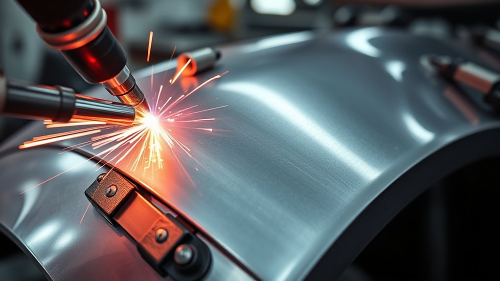
ER70S-6 works well for approved patch-panel repairs because it starts smoothly, wets into a properly fitted joint, and supports small controlled tacks. The goal is not to build a heavy bead. The goal is sound fusion with the least heat and shrinkage needed for the repair.
| Benefit | Result | Use |
|---|---|---|
| Smooth starts | Cleaner, more repeatable tacks | Butt-fit patch panels |
| Deoxidizing alloy | More margin against minor residual oxidation after prep | Restoration sheet metal |
| Controllable puddle | Less unnecessary weld buildup and grinding | Thin mild-steel sheet |
Patch-Panel Workflow
- Verify the repair: Confirm the panel material, cut location, joint design, welding process, filler, plug-weld size, spacing, adhesive, and corrosion-protection requirements in the OEM information.
- Make the vehicle safe: Follow the manufacturer’s depowering procedure. Protect fuel, SRS, wiring, modules, batteries, and high-voltage parts. Inspect both sides of the proposed weld zone.
- Cut back to sound metal: Remove weak, perforated, or deeply pitted steel rather than trying to fill it with weld.
- Prepare both sides: Remove paint, zinc where the procedure requires it, rust, adhesive, seam sealer, oil, undercoating, and moisture from the weld area.
- Fit and clamp the patch: Keep the specified gap uniform. A loose patch needs more filler and creates more heat and shrinkage.
- Prepare a matching test coupon: Reproduce the panel gauge and joint, then verify machine settings and fusion before touching the vehicle.
- Place the initial tacks: Lock the patch in position with widely spaced tacks while checking alignment and panel shape.
- Fill the seam gradually: Move around the repair, place short tacks between cooled tacks, and stop if the panel begins to distort.
- Inspect before grinding: Check the face and backside where accessible for fusion, pinholes, cracks, and burn-through.
- Dress the weld carefully: Remove only the excess bead and silicon deposits. Do not grind deeply into the original panel.
- Restore protection: Apply the specified weld-through treatment, primer, adhesive, seam sealer, undercoating, or cavity wax at the correct stage of the repair.
- Complete the fire watch: Check concealed cavities and the opposite side of the repair for smoldering material after hot work ends.
For plug welds, lap joints, flanges, and structural sections, follow the OEM hole diameter, spacing, panel stack, adhesive, and weld-placement requirements. Do not replace an OEM spot weld, MIG-brazed joint, rivet, or adhesive joint with a generic plug weld unless the procedure permits it.
If you must work outdoors, shield the weld from wind or select a process approved for the repair and conditions. A wire such as Forney flux-core MIG wire is designed for a different use case than gas-shielded ER70S-6 and should not be treated as an automatic substitute on an automotive panel.
Choosing the Right ER70S-6 Wire Diameter
Wire diameter affects the usable current range, arc response, deposition rate, and how easily you can control each tack. For auto body work, smaller wire is normally easier to use because it melts at a lower current and produces a smaller deposit.
| Wire Diameter | Best Use | Why It Helps |
|---|---|---|
| 0.023 or 0.024 inch | Light-gauge body sheet | Lower usable current and easier control of small tacks |
| 0.030 inch | 18-gauge and thicker sheet, brackets, and general repair | Good balance of feed reliability, control, and deposition |
| 0.035 inch | Heavier approved brackets and thicker mild-steel fabrication | Higher deposition, but generally too much heat for very thin body sheet |
If you mainly weld body panels, begin with 0.023- or 0.024-inch wire if your machine supports it. Some brands label the nominal 0.6 mm size as 0.023 inch, while others use 0.024 or 0.025 inch. Match the drive roll, liner, and contact tip to the manufacturer’s stated diameter.
If your machine feeds 0.030-inch wire more consistently and the approved repair is on 18-gauge or thicker mild steel, 0.030 inch can work well. Save 0.035 inch for heavier material where its higher deposition and heat are appropriate.
The same ER70S-6 classification can also be supplied as TIG filler rod, but TIG and MIG require different equipment and technique. For TIG-specific use, see this mild-steel TIG welding rod ER70S-6 review.
Safe Prep and Setup Before Welding
Good ER70S-6 welds begin before the trigger is pulled. Prepare the metal, vehicle, equipment, and work area so contamination, electrical damage, fumes, and fire hazards are controlled.
- Confirm the OEM procedure: Identify the vehicle by VIN and model year, then verify the panel material, joint design, repairability, filler, process, and corrosion-protection requirements.
- Depower the vehicle correctly: Follow the manufacturer’s sequence for the 12 V system, capacitors, modules, SRS components, hybrid battery, and high-voltage system. Disconnecting the 12 V battery alone is not a complete EV or hybrid safety procedure.
- Protect electronics: Follow OEM guidance for module disconnection, grounding, memory retention, and work-lead placement. Keep welding current paths away from bearings, modules, wiring, and control units.
- Inspect both sides: Locate carpet, insulation, foam, adhesives, seam sealer, fuel and brake lines, wiring, hoses, trim, and closed cavities behind the weld.
- Expose sound metal: Remove paint, primer, rust scale, oil, adhesive, seam sealer, undercoating, and other contamination from the joint.
- Control coating fumes: Remove zinc and other coatings as directed by the repair procedure and use suitable local exhaust. Do not place your head in the fume plume.
- Eliminate solvent hazards: Keep chlorinated cleaners and their vapors away from welding. Follow the cleaner manufacturer’s instructions and allow approved cleaners to evaporate fully.
- Prepare fire protection: Remove or shield combustibles, keep an appropriate extinguisher ready, and establish a fire watch when conditions require one.
- Check gas coverage: Use the specified gas, a clean nozzle, sound hose connections, correct flow, and protection from drafts.
- Set the machine: Match DCEP polarity, wire size, drive roll, liner, contact tip, voltage, and wire speed to the machine chart.
- Test first: Weld and inspect scrap that matches the panel gauge and joint before welding the vehicle.
- Restore corrosion protection: After welding, inspection, and cleaning, replace the specified primers, sealers, adhesives, undercoating, and cavity protection on both sides where required.
- Watch for delayed fire: Reinspect the weld area and concealed cavities after work. Where a fire watch is required, OSHA specifies at least 30 minutes after welding or cutting ends.
For workplace requirements, review OSHA 29 CFR 1910.252. For welding-fume and engineering-control guidance, review the NIOSH welding-fume control resource.
Frequently Asked Questions
What MIG wire is best for auto body?
ER70S-6 is a common starting wire for OEM-approved GMAW repairs on mild-steel body panels. Use 0.023- or 0.024-inch wire for light-gauge sheet and C25 gas for clean short-circuit welding. Confirm the vehicle maker’s repair procedure before welding structural or high-strength steel.
What does ER70S-6 stand for?
“ER” means the filler may be supplied as an electrode or rod. “70” identifies the 70 ksi tensile-strength class, “S” means solid wire, and “6” identifies its chemical-composition classification, including relatively high silicon and manganese deoxidizer levels.
What is the difference between ER70S-6 and ER70S-3?
ER70S-6 has more silicon and manganese deoxidizing action, so it offers more margin on mild steel with light mill scale or oxidation after preparation. ER70S-3 is intended for clean steel and may leave fewer silicon deposits before painting or plating.
Can ER70S-6 weld rusty steel?
ER70S-6 can tolerate light residual oxidation better than ER70S-3, but it should not be used to bury heavy rust. Remove corrosion until you reach sound metal. Replace sections that are deeply pitted, thin, perforated, or structurally weak.
What shielding gas should I use with ER70S-6?
Use 75% argon and 25% CO2 for most thin mild-steel auto body work. It gives a stable short-circuit arc and less spatter than straight CO2. Start near the flow recommended by your welder and gun manufacturer; approximately 20–25 CFH is common for a small indoor setup.
Is 0.023 or 0.030 wire better for auto body panels?
Use 0.023- or 0.024-inch wire for very thin sheet because it works at a lower current and makes small tacks easier to control. Use 0.030-inch wire for 18-gauge and thicker sheet, brackets, and general repairs when the machine feeds it smoothly.
What polarity does ER70S-6 use?
Solid ER70S-6 normally uses direct-current electrode positive, or DCEP. The MIG gun connects to positive and the work lead connects to negative. Check the welder and wire instructions before changing polarity because self-shielded flux-core wire often uses a different connection.
Can I weld galvanized auto body steel with ER70S-6?
Only when the OEM procedure permits GMAW at that location. Remove zinc from the weld zone as directed, use suitable local exhaust, and restore the specified corrosion protection afterward. Zinc fumes are hazardous, and the coating can cause porosity and an unstable arc.
Can ER70S-6 weld high-strength automotive steel?
Do not assume that it can. Some high-strength steels allow limited welding in specified areas, while others must not be heated or repaired with conventional GMAW. Use the exact VIN-, model-year-, panel-, and joint-specific OEM repair procedure.
Do ER70S-6 welds need cleaning before paint?
Yes. Remove spatter, residue, contamination, and glassy silicon-island deposits before primer, paint, seam sealer, plating, adhesive, or other surface conditioning. Clean gently so you do not thin the surrounding sheet metal.
Conclusion
ER70S-6 earns its place in auto body repair because it is widely available, easy to feed, smooth in short-circuit transfer, and more tolerant of light oxidation than ER70S-3. With 0.023- or 0.024-inch wire, C25 gas, DCEP polarity, accurate fit-up, and spaced tacks, it can produce clean repairs on approved mild-steel panels.
The wire is only one part of a safe repair. Confirm the OEM joining method, identify the material, depower the vehicle correctly, remove contamination and hazardous coatings, test the setup on matching scrap, inspect fusion, clean silicon deposits, and restore corrosion protection. Those steps matter more than any generic voltage number or claim that one wire can weld every automotive steel.
Sources
- American Welding Society AWS A5.18/A5.18M:2021 — current classification specification for carbon-steel electrodes and rods used in gas-shielded arc welding.
- Hobart Filler Metals HB-28 ER70S-6 Datasheet — chemistry ranges, DCEP polarity, shielding gases, wire diameters, and mechanical-property data.
- Hobart Filler Metals: Choosing a Solid Wire — ER70S-6 and ER70S-3 comparison, deoxidizer guidance, shielding gas, and silicon-island cleanup.
- Miller Electric: Successfully Welding Sheet Metal — thin-sheet wire diameter, C25 gas, DCEP, and heat-control guidance.
- OSHA 29 CFR 1910.252 — fire prevention, eye protection, ventilation, zinc, and other hot-work safety requirements.
- CDC/NIOSH Welding Fume Engineering Controls — welding-fume hazards and exposure-control guidance.