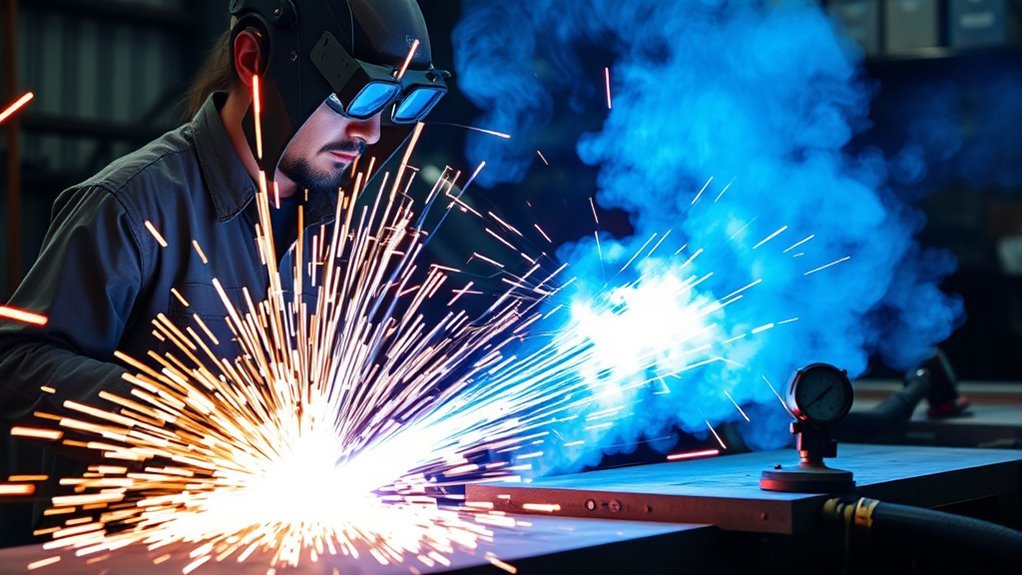
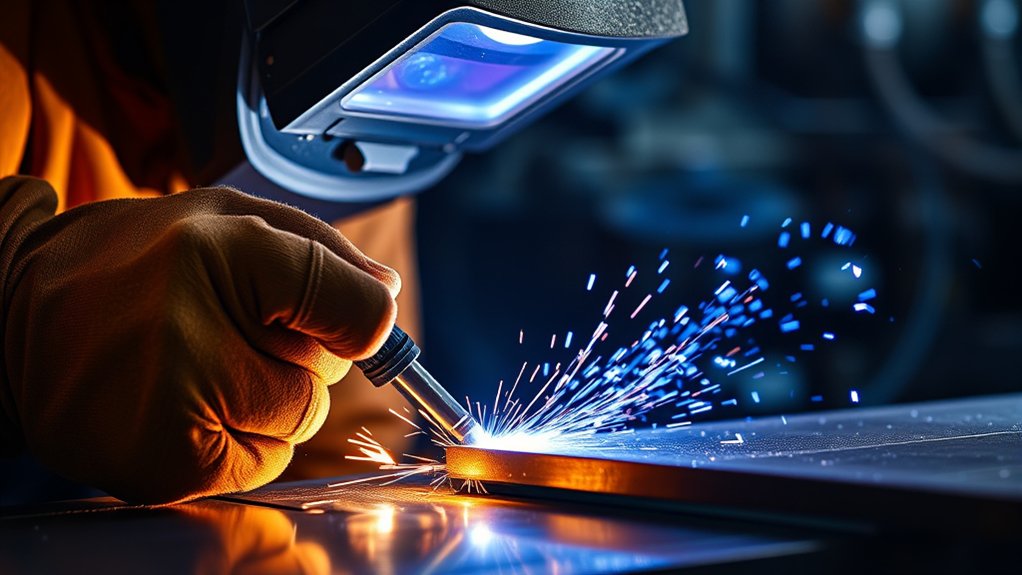
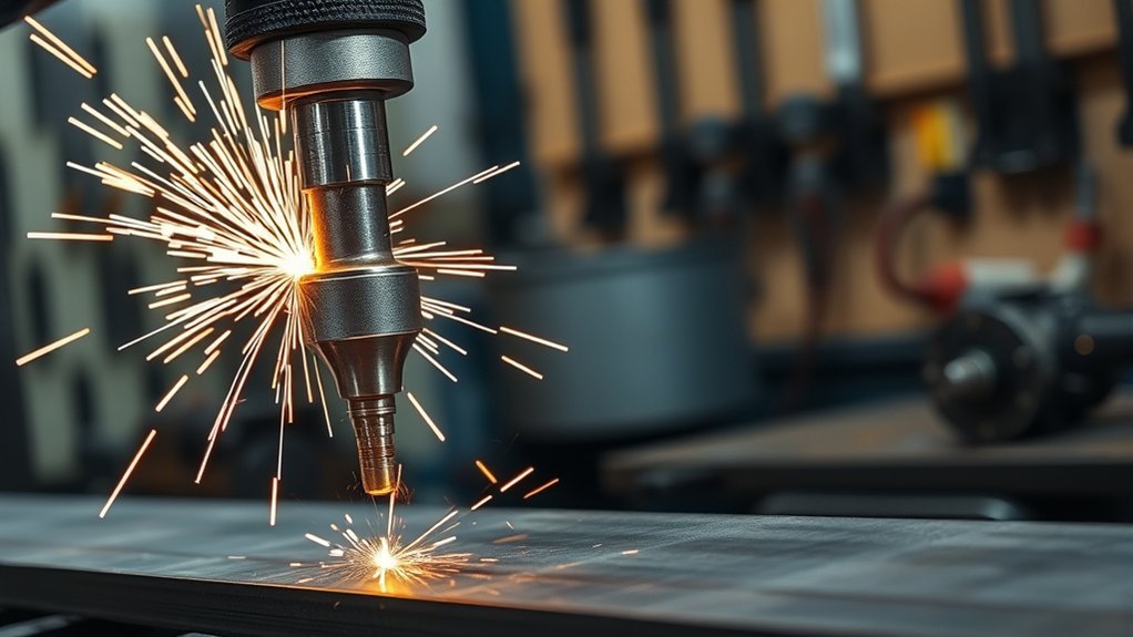
A pilot arc plasma cutter starts a small arc inside the torch before the main cutting arc transfers to the workpiece. That makes arc starting more reliable on rusty, painted, dirty, or perforated metal, but it does not remove the need for a clean work-clamp connection, correct air pressure, suitable consumables, and proper safety controls.
Quick Answer
A pilot arc plasma cutter forms a low-current, non-transferred arc between the electrode and nozzle, then transfers the main arc to conductive metal. It starts without the bare nozzle completing the circuit, so it handles coatings, rust, and expanded metal better than basic direct-contact systems.
Updated July 20, 2026.
What is a pilot arc plasma cutter?
It is a plasma cutting system that establishes an internal pilot arc before transferring cutting current to the workpiece. The process can start through light rust, paint, or dirt along the cut path, although the work clamp still needs clean, solid metal-to-metal contact.
Pilot arc systems are common in repair, fabrication, construction, metal art, and automated cutting. They can produce fast, clean cuts when the machine, consumables, travel speed, torch height, and air supply match the material. They do not automatically eliminate dross or make every cut more precise.
Key Takeaways
- The pilot arc forms inside the torch, then the main arc transfers to electrically conductive metal.
- Pilot arc and starting technology are separate ideas: both high-frequency and blowback/contact-start designs can create a pilot arc.
- Rust or paint may remain in the cut path, but the work clamp must contact clean bare metal.
- Expanded-metal performance, cut quality, and consumable life still depend on the machine’s mode, air quality, settings, and operator technique.
- Plasma cutting creates intense light, heat, noise, sparks, and fumes; use the manufacturer’s manual and applicable hot-work controls.
Understanding Pilot Arc Plasma Cutting

A plasma cutter sends pressurized gas through a narrow torch opening while direct current energizes the gas. The ionized gas becomes an electrically conductive plasma jet. Plasma systems work on electrically conductive metals, including mild steel, stainless steel, aluminum, copper, brass, and titanium.
In a pilot arc torch, the first arc is non-transferred: it exists between the electrode and nozzle inside the torch. When the torch approaches a properly connected workpiece, current transfers through the metal and creates the higher-energy cutting arc.
- Trigger and gas flow: Pulling the trigger starts a safety sequence and gas flow, subject to the machine’s interlocks.
- Pilot arc formation: The starting circuit ionizes the gas and creates a low-current arc inside the torch.
- Arc transfer: When the plasma jet reaches conductive metal connected to the work lead, the main cutting arc transfers to the workpiece.
- Cutting: The concentrated arc melts a narrow path while the gas stream blows molten metal out of the kerf.
- Postflow: After release, many machines continue gas flow to cool the torch and consumables.
Note: A pilot arc can start through light surface contamination, but it cannot replace the electrical return path. Attach the work clamp to clean bare metal on the part or cutting table, not to the piece that will fall away.
The plasma arc can approach 40,000°F. That temperature explains the process’s speed, but cut quality depends on more than heat. Incorrect travel speed, worn consumables, wet air, wrong amperage, excessive standoff, and poor work-lead contact can all create bevel, dross, a wide kerf, or incomplete cuts.
Mechanisms of Pilot Arc Formation
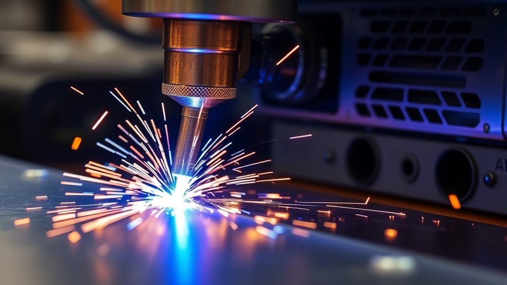
The words pilot arc, high-frequency start, and contact start describe different parts of the process. The pilot arc is the internal arc. The starting method is how the machine creates it.
Pilot Arc Initiation Methods
- High-frequency (HF) start: A high-voltage, high-frequency signal ionizes the gas and initiates the pilot arc. HF starting is effective, but electromagnetic interference can affect nearby CNC controls, computers, communication equipment, and other electronics if the installation is not designed for it.
- Blowback or contact start: Air pressure moves the electrode or another internal torch component to create and then break an internal electrical contact. The break initiates the arc without using external HF. This design is common in modern handheld systems and is generally friendlier to nearby electronics.
- Capacitive-discharge or other electronic starts: Some systems use proprietary low-frequency electronic starting circuits. Terminology varies, so the operator manual is the best source for the exact design and CNC requirements.
A contact-start torch can still be a pilot arc torch. “Contact” may refer to contact between parts inside the torch, not necessarily to dragging the bare nozzle on the workpiece. Likewise, some pilot arc systems are designed for drag cutting with a shield that maintains the correct internal standoff.
Arc Stability on Expanded and Coated Metal
Expanded metal, grating, and perforated sheet repeatedly interrupt the transferred arc. A cutter with an expanded-metal mode or automatic pilot-arc control can switch between pilot and cutting arcs as the torch crosses gaps. That reduces repeated trigger pulls and helps maintain forward motion. It does not guarantee a perfect arc under every condition; air pressure, gap size, consumable condition, and machine capability still matter.
Pilot arc improves starting and gap-crossing reliability; it does not replace correct settings or good electrical contact.
Key Advantages and Limitations of a Pilot Arc Plasma Cutter
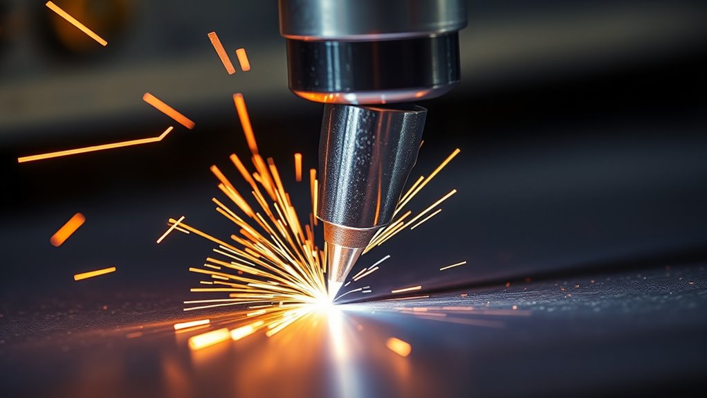
Advantages
- Reliable starts on imperfect surfaces: Light rust, paint, mill scale, and dirt along the cut path are less likely to prevent arc initiation.
- Better performance on gaps: Properly equipped machines can cut grating, mesh, and expanded metal without restarting after every opening.
- Flexible torch positioning: The operator can establish the arc before the cutting jet fully transfers to the workpiece.
- Reduced dependence on exposed-tip contact: The nozzle does not need to complete the work circuit against the plate. A drag shield may still touch the surface when the torch is designed for drag cutting.
- Useful for repair work: It reduces surface-preparation time on rusty automotive, farm, construction, and salvage parts.
Limitations
- Higher cost and complexity: Pilot arc machines and their torches may cost more than very basic direct-contact cutters.
- Consumable wear during prolonged pilot operation: Holding a pilot arc without transferring it can wear the electrode and nozzle, so do not fire the torch unnecessarily.
- Coatings still create hazards: Paint, galvanizing, plating, and unknown residues can release hazardous fumes even when the cutter can physically cut through them.
- Not for nonconductive materials: A standard plasma cutter will not properly cut wood, plastic, glass, concrete, or other electrically nonconductive materials.
- No automatic quality advantage: Pilot arc does not by itself guarantee less dross, a square edge, or laser-like precision.
Applications and Materials
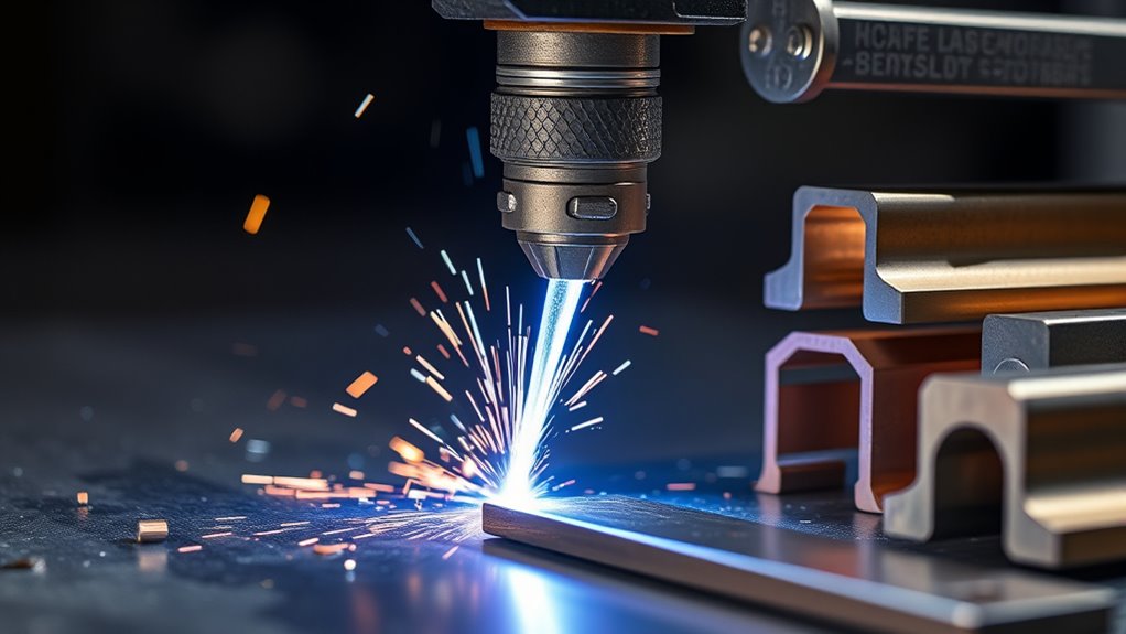
Pilot arc cutters are useful wherever conductive metal may be rusty, coated, irregular, or perforated:
- Automotive repair and restoration: Removing rusted body panels, brackets, exhaust parts, and damaged sheet metal. Avoid cutting near fuel, brake, refrigerant, airbag, high-voltage, or wiring systems until they are identified and safely isolated.
- Farm and equipment repair: Cutting weathered plate, seized fasteners, guards, and structural parts in the field or shop.
- Construction and demolition: Resizing steel plate, angle, channel, grating, and other conductive components, subject to engineering and hot-work controls.
- Shipbuilding and heavy fabrication: Cutting oxidized plate and structural shapes with machines sized for the material thickness.
- Metal art and signs: Freehand or CNC cutting of sheet, plate, and perforated patterns.
- Aerospace and specialty fabrication: Cutting aluminum, stainless steel, and titanium where the approved process, equipment, traceability, and finish requirements allow plasma cutting.
Air plasma can cut many conductive metals, but the cut edge differs by material. Air-cut stainless steel and aluminum may show oxidation or nitriding that affects appearance or downstream welding. Use the gas, consumables, and edge-preparation method specified for the job.
Pilot Arc vs. Direct-Contact or Non-Pilot Systems
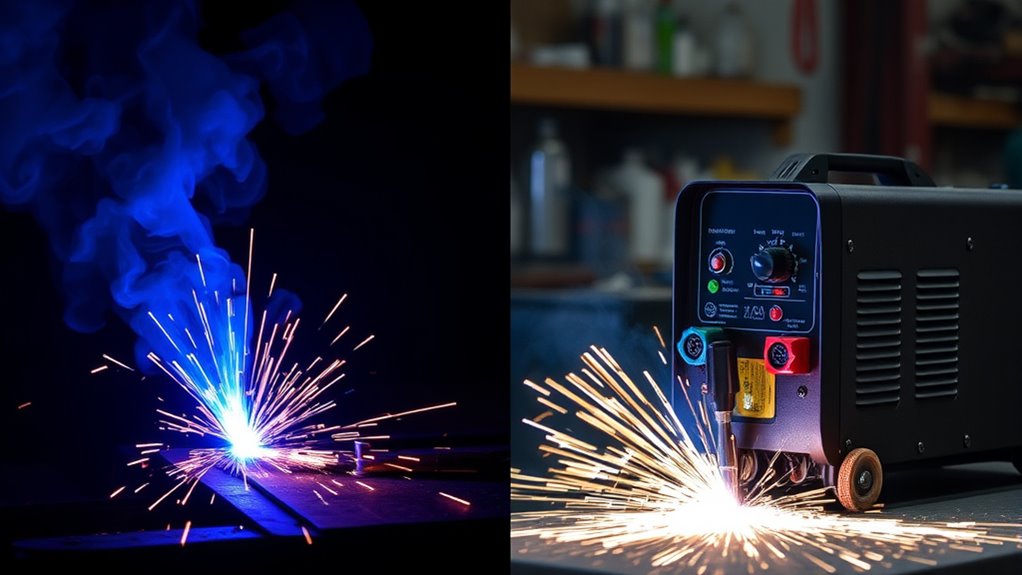
Low-cost cutters are often described as “touch start” or “scratch start,” but those labels are not standardized. Some contact-start torches create a pilot arc internally, while a true direct-contact system may depend on the nozzle or tip contacting clean metal to establish the arc. Check the manual rather than relying only on marketplace wording.
| Feature | Pilot Arc System | Basic Direct-Contact System |
|---|---|---|
| Arc initiation | Internal pilot arc forms before transfer | May require the exposed tip to touch clean metal |
| Painted or rusty cut path | Usually more reliable through light contamination | Often needs more cleaning where the arc starts |
| Work-clamp area | Clean bare metal still required | Clean bare metal required |
| Expanded metal | Good when the machine has automatic re-fire or expanded-metal mode | More likely to stop at gaps and require re-triggering |
| Consumable life | Can be good with correct use; excessive pilot time still causes wear | Tip contact and double-arcing may increase wear on some designs |
| Price | Usually higher | Usually lower |
Products Worth Considering

【Non-Touch Pilot Arc Function】The ARCCAPTAIN 55A plasma cutter features a pilot arc function. It utilizes a high-frequency non-touch arc starting mode. The torch head does not need to touch the metal plate, reducing energy consumption during non-cutting work, minimizing electrode burning, and extending service life. NOTE: Do not switch voltages until the screen turns off and the fan stops.

[Powerful Cutting Ability] Dual voltage 110/220V good for home, workshop and hardware shop use. Professional performance 1/2" clean cuts on Iron, Steel aluminum and copper with Inverter IGBT Technology. Very powerful for DIY and heavy duty project. The Maximum cutting thickness is recommended to 1/2" @35A 110V 50PSI; 2/3" @50A 220V 65PSI. Dry and compressed air is required. Power breaker up to 60A@110V 35A; Up to 50A@220V 50A.

【Non-Touch Pilot Arc Function】The plasma cutter features a high frequency non-touch arc starting mode. It allows for cutting steel surfaces with dirt, rust or coatings. The torch head does not need to touch the metal plate, reducing energy consumption, minimizing electrode burning, and extending service life. NOTE: DO NOT power on until the screen turns off and the fan stops working!
Essential Components
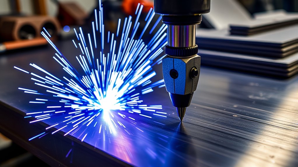
- Power supply: Converts line power into controlled direct-current output. In many handheld machines, the starting circuitry is integrated into the power supply rather than housed in a separate arc-start console.
- Torch and lead: Carry current and gas to the torch. Safety interlocks help prevent operation when the retaining cap or cartridge is not installed correctly.
- Electrode: Conducts current and supports arc formation. A worn electrode may have a deep pit or other damage defined by the manufacturer.
- Swirl ring: Directs and spins the gas to stabilize the arc and cool torch parts. It must be clean and undamaged.
- Nozzle or tip: Constricts the arc and shapes the plasma jet. An enlarged or irregular orifice can cause bevel and a wandering arc.
- Retaining cap, shield, or deflector: Holds parts in place and protects the nozzle. A drag shield may let the operator rest the torch on the plate while maintaining the designed standoff.
- Work lead and clamp: Complete the cutting circuit. The connection must be secure and on clean metal.
- Gas supply and filtration: Most portable air-plasma systems require compressed air at a specified pressure and flow. The air must be clean, dry, and oil-free unless the manual states otherwise.
Safety Considerations and Best Practices
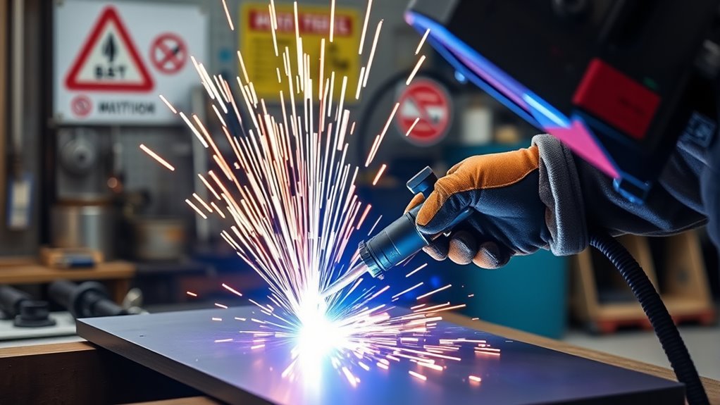
Warning: Never cut a sealed, pressurized, or unverified drum, tank, pipe, fuel container, cylinder, or hollow part. Residue can create an explosive atmosphere even when the container looks empty. Hot work on containers requires proper cleaning, ventilation, testing, and pressure relief by qualified personnel.
At a Glance
| Time Required | About 10–15 minutes for inspection and setup, plus cutting and cooldown time |
| Difficulty | Beginner-friendly after training, but the electrical, fire, light, noise, and fume hazards are serious |
| Tools Needed | Compatible cutter and torch, correct consumables, work clamp, specified gas supply, PPE, ventilation, and fire-control equipment |
| Cost | Varies by machine, electrical service, compressor, filtration, consumables, and required PPE |
Pre-Cut Safety Checklist
- Read the manual: Use only the consumables, input power, gas pressure, flow, and torch technique approved for the machine.
- Protect eyes and face: Plasma cutting produces ultraviolet and infrared radiation plus flying molten metal. OSHA’s filter-lens table lists shade 8 for light plasma arc cutting below 300 amps, shade 9 for 300–400 amps, and shade 10 for 400–800 amps. Follow the machine manual and applicable workplace rules.
- Wear full PPE: Use safety glasses under an approved cutting helmet or shield, flame-resistant clothing, leather gloves, hearing protection, and closed leather footwear. Cover exposed skin.
- Control fumes: Identify the base metal, plating, paint, primer, oil, and residue before cutting. Use local exhaust or other effective ventilation. A respirator is not a substitute for hazard assessment, correct filter selection, fit testing, and a respiratory-protection program where one is required.
- Prevent fire: Remove combustibles, protect nearby openings, control sparks and slag, keep suitable fire-extinguishing equipment ready, and use a fire watch when conditions require it.
- Inspect the area below the cut: Molten metal passes through the workpiece. Keep people, hoses, cords, vehicle parts, and combustibles out of the drop zone.
- Keep the system dry: Do not operate in rain, standing water, or wet clothing. Follow the manual’s electrical grounding and work-lead instructions.
- Isolate vehicle hazards: Before automotive cutting, identify and protect fuel lines, fuel tanks, batteries, air-conditioning refrigerant lines, brake lines, airbags, wiring, and high-voltage hybrid or EV components.
Basic Operating Sequence
- Verify that the machine, circuit, torch, consumables, and gas supply match the planned material and thickness.
- Inspect the electrode, nozzle, shield, swirl ring, torch lead, power cord, air hose, and work lead. Replace damaged parts.
- Remove flammable or toxic coatings from the immediate heat zone when required, and provide effective ventilation.
- Attach the work clamp to clean bare metal as close to the cut as practical, on the section that will remain supported.
- Set the operating mode, amperage, and gas pressure or confirm the machine’s automatic settings.
- Position the torch at the edge, or use the manual’s approved pierce angle and standoff for an interior start.
- Pull the trigger, allow the arc to transfer, then move at a steady speed. Sparks should generally pass through the plate and trail slightly behind the torch.
- Release the trigger at the end of the cut. Allow postflow to finish before removing the torch or turning off the air supply.
- Treat the workpiece, offcut, and slag as hot until verified otherwise.
Pro Tip: Make test cuts on scrap of the same material and thickness. Adjust one variable at a time—usually travel speed first—before changing amperage, torch height, or air pressure.
Maintaining Your Pilot Arc Plasma Cutter

Routine maintenance improves reliability, cut quality, and consumable life. Always turn off and isolate input power before opening the machine or servicing components, and leave internal electrical work to qualified technicians.
- Inspect consumables before use: Look for electrode wear, an enlarged or notched nozzle opening, cracked swirl rings, damaged O-rings, and spatter on the shield.
- Replace parts as a matched system: Do not mix incompatible electrodes, nozzles, shields, caps, or cartridges.
- Maintain clean, dry, oil-free air: Drain the compressor tank, service filters and water separators, and keep hoses free of contamination. Follow the machine’s pressure and flow specification rather than using a universal PSI setting.
- Clean cooling openings: Remove dust from external vents as the manual directs. Do not blow debris deeper into energized equipment.
- Protect leads and cables: Avoid sharp bends, hot slag, vehicle traffic, and pulling the machine by its leads.
- Record recurring faults: Repeated low-pressure, cap-sensor, over-temperature, or arc-transfer faults often point to a setup or maintenance problem.
Tip: A deeply pitted electrode or widened nozzle orifice can make the arc wander, increase bevel, and reduce cut quality. Use the manufacturer’s wear limits instead of judging parts only by arc-start count.
Troubleshooting Common Problems
| Problem | Likely Checks |
|---|---|
| Pilot arc starts but will not transfer | Clean and tighten the work clamp, move it closer, confirm conductive material, reduce excessive standoff, and inspect the work lead. |
| Arc sputters or stops | Check air pressure and flow under load, moisture or oil contamination, loose consumables, worn parts, and duty-cycle limits. |
| Heavy bottom dross | Travel may be too slow, amperage may be too high for the speed, or the torch may be too far from the plate. |
| Cut does not penetrate | Travel may be too fast, output too low, material too thick, air flow inadequate, consumables worn, or input power undersized. |
| Excessive bevel or wandering arc | Inspect nozzle and electrode wear, torch angle, travel direction, standoff, air quality, and torch damage. |
| Consumables fail early | Check wet or oily air, incorrect parts, loose installation, excessive pilot time, piercing too close, and shutting off air before postflow ends. |
Choosing the Right Pilot Arc Plasma Cutter
- Recommended cut capacity: Size the machine for the thickness you cut most often. Recommended capacity is more useful for routine work than the much slower severance rating.
- Pierce capacity: Interior starts are harder on the torch than edge starts. CNC users should compare mechanized pierce capacity, not only hand-cut severance thickness.
- Expanded-metal control: Look for an expanded-metal mode, automatic re-fire, or equivalent pilot-arc control if you cut grating or perforated sheet.
- Start technology: Choose non-HF blowback/contact-start equipment when the cutter will operate near CNC controls or sensitive electronics, unless the installation is specifically designed and grounded for HF.
- Input power: Confirm voltage, phase, plug, branch-circuit amperage, extension-cord limits, and generator requirements. “Dual voltage” does not mean full output is available on the lower voltage.
- Duty cycle: A rating such as 60% at 40 amps means the machine can cut for a stated portion of a standardized test period at that output and ambient condition before cooling. Compare ratings at the same amperage and temperature.
- Air requirement: Check both pressure and flow. A compressor that reaches the stated PSI but cannot maintain the required cubic feet per minute may cause poor cuts and faults.
- Torch style and consumables: Consider drag-cutting support, visibility, torch-lead length, safety trigger, cartridge or multi-piece consumables, local availability, and cost per cut.
- Portability and support: Include machine weight, built-in compressor options, warranty, service access, manuals, and genuine consumable availability.
For CNC use, confirm that the machine supports mechanized cutting, has the required machine interface or voltage divider, and uses a start system compatible with the table controls. A handheld torch clamped to a table is not automatically a safe or supported mechanized system.
Products Worth Considering
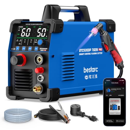
[Smart APP Remote Control Up to 98FT] Control your plasma cutter from up to 98 ft (30 m) away via Bluetooth APP. Adjust cutting current, switch cutting modes, save preferred settings, monitor operating status, and check error codes directly from your phone. Reduce trips back to the machine and work more efficiently—ideal for workshops, auto repair, farms, garages, and DIY projects.

NON-HIGH FREQUENCY: The ''blow-back'' start system offers a remarkably smooth and interference-free initiation of the engine. This method is inherently safe for operators and bystanders, posing minimal risk to human health. Furthermore, it operates harmoniously with surrounding electrical machinery, preventing potential disruptions.

【Powerful Cutting Ability】Dual voltage plasma cutter 110 220 operation is perfect for home garages, workshops, and hardware shops. Delivers professional performance 1/2" clean cuts on iron, steel, aluminum and copper using Inverter IGBT Technology. Suitable for both DIY and heavy-duty projects. Maximum recommended cutting thickness: 1/2" @ 35A 110V 50 PSI; 2/3" @ 50A 220V 65 PSI. Requires dry, compressed air. Recommended power breakers: 40A @ 110V; 30A @ 220V.
Current and Future Trends

Plasma systems are moving toward simpler setup, better process control, and more useful maintenance data. Current professional systems already offer automatic gas regulation, cartridge-style consumables, automatic amperage and mode selection, consumable-use tracking, fault codes, and CNC integration. HF-free starting remains important in digital shops because it reduces electromagnetic-interference concerns.
Future improvements are likely to focus on longer consumable life, better cut consistency on imperfect material, lower operating cost, easier diagnostics, and tighter integration between the power supply, torch, height control, CNC, and nesting software. These features can reduce setup errors, but they do not remove the need for trained operators, correct ventilation, and routine inspection.
Frequently Asked Questions
How does a pilot arc work?
The machine creates a low-current arc between the electrode and nozzle inside the torch. When the plasma jet reaches conductive metal connected to the work lead, the current transfers to the workpiece and becomes the main cutting arc.
Is pilot arc the same as high-frequency start?
No. Pilot arc describes the arc that forms inside the torch. High-frequency start is one method used to create that arc. Blowback or contact-start torches can also create a pilot arc without external high-frequency starting.
What is the difference between a touch arc and a pilot arc plasma cutter?
A basic direct-contact cutter may need its exposed tip to touch clean metal to establish the arc. A pilot arc cutter forms an internal arc before transfer. However, “touch,” “contact,” and “scratch” are used inconsistently in product listings, so verify the torch design in the manual.
Can a pilot arc plasma cutter cut painted or rusty metal?
Yes, it can usually start and cut through light paint, rust, or dirt along the cut path. The work clamp must still contact clean bare metal, and coatings may release hazardous fumes. Heavy contamination can also reduce cut quality.
Can the torch touch the workpiece?
It depends on the torch and consumables. Some systems use a drag shield designed to rest on the plate while preserving the correct standoff. Other setups require the operator to hold the torch above the work. Follow the manual for the installed parts.
What metals can a pilot arc plasma cutter cut?
It can cut electrically conductive metals within the machine’s capacity, including mild steel, stainless steel, aluminum, copper, brass, and titanium. Standard plasma cutters are not intended for wood, plastic, glass, or other nonconductive materials.
What are the disadvantages of plasma arc cutting?
Disadvantages include equipment and consumable cost, compressed-air requirements, noise, intense arc light, sparks, fumes, and edge bevel or dross when settings are wrong. Very tight-tolerance or very thick work may be better suited to another cutting process.
Why does the pilot arc start but fail to cut?
The main arc may not be transferring. Check for a clean, tight work-clamp connection, excessive torch distance, nonconductive material, inadequate air flow, worn consumables, a damaged work lead, or a machine fault.
Conclusion
A pilot arc plasma cutter is a strong choice for rusty, painted, dirty, or perforated conductive metal because it forms an internal arc before transferring cutting current to the workpiece. Its biggest benefit is reliable starting, not automatic perfection. Clean work-clamp contact, correct consumables, dry air, proper speed, and safe hot-work practices still determine the result.
Choose a machine by recommended cut and pierce capacity, duty cycle, input power, air demand, start technology, torch design, and service support. For CNC use, confirm that the model is designed for mechanized operation and compatible with the table controls.
Sources
- Hypertherm: Understanding Plasma Attributes — conductive materials, painted or rusty surfaces, and expanded metal.
- Hypertherm: Powermax45 XP Setup — clean work-clamp contact, filtered air, consumables, and setup.
- Miller Electric: Hand-Held Plasma Cutter Guide — HF and contact starting, standoff, selection, and operation.
- Miller Electric: Plasma Cutting Safety — PPE, coatings, fumes, and hot-work precautions.
- OSHA 29 CFR 1910.133 — eye and face protection and plasma arc cutting filter shades.
- OSHA 29 CFR 1910.252 — welding and cutting fire prevention, ventilation, and container precautions.