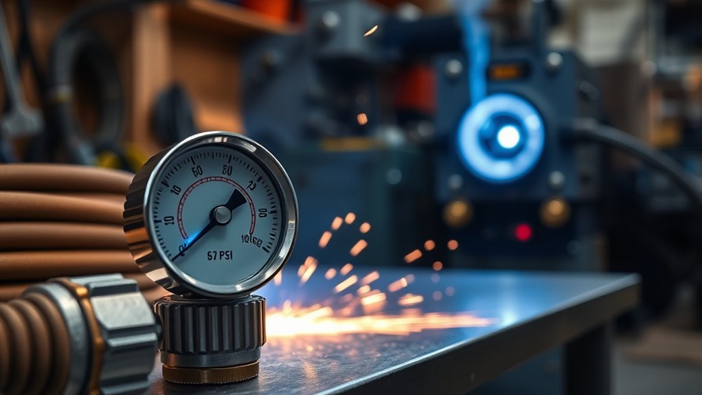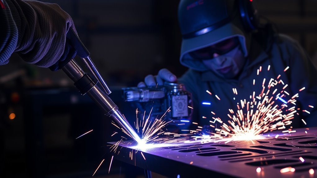
A plasma torch turns electricity and a fast-moving gas into a narrow jet hot enough to melt metal almost instantly. Understanding the sequence—from gas preflow and pilot-arc starting to arc transfer and postflow cooling—makes it easier to choose equipment, diagnose poor cuts, and operate a plasma cutter safely.
Quick Answer
A plasma torch forces gas through a narrow nozzle and energizes it with a DC electric arc. The gas becomes electrically conductive plasma that can approach 40,000°F. The focused jet melts conductive metal, while the high-speed gas blows molten material out of the kerf to form the cut.
Key Takeaways
- Plasma is conductive gas: Free electrons and positive ions allow an electric current to pass through the gas.
- The torch uses two forces: Arc energy melts the metal, and gas velocity ejects the molten material.
- The pilot arc and cutting arc are different: The pilot arc starts inside the torch before the main arc transfers to the workpiece.
- Air quality matters: Moisture, oil, low pressure, or insufficient airflow can damage consumables and reduce cut quality.
- Standard plasma cutters need conductive material: They cut metals such as steel, stainless steel, aluminum, copper, and brass—not wood, glass, or plastic.
- Safety is essential: Plasma cutting creates severe shock, burn, eye, fire, noise, and fume hazards.
Warning: A plasma arc can cause fatal electric shock, severe burns, eye damage, fire, and hazardous fume exposure. Read the machine’s operator manual, wear the specified PPE, provide suitable ventilation, remove fire hazards, and never cut a sealed or pressurized container.
How a Plasma Torch Works Step by Step
Most shop plasma cutters use a direct-current, transferred-arc process. The torch and workpiece become parts of the electrical circuit, while compressed gas carries the heat and clears molten metal from the cut.
- The trigger starts gas preflow. Compressed air or another approved plasma gas begins moving through the torch before full cutting current is applied. The preflow clears the torch passage and establishes the correct gas stream.
- A pilot arc starts. Depending on the machine, a blowback mechanism or high-frequency circuit creates a small arc between the electrode and nozzle.
- The arc transfers to the workpiece. When the pilot arc reaches conductive metal connected to the work lead, current transfers from the nozzle to the workpiece. This becomes the main cutting arc.
- The nozzle constricts the arc. The nozzle opening and controlled gas swirl squeeze the arc into a narrow, high-energy column.
- The metal melts and leaves the kerf. Arc heat melts a narrow path through the workpiece, and the fast gas stream blows the liquid metal out of the bottom of the cut.
- Postflow cools the torch. Gas continues flowing for a short period after the trigger is released. This protects the electrode, nozzle, and other torch parts from heat damage.
Note: The work clamp completes the cutting circuit, but it is not a substitute for the machine’s protective electrical ground. Follow the manufacturer’s grounding and work-lead instructions.
Understanding Plasma: The Fourth State of Matter
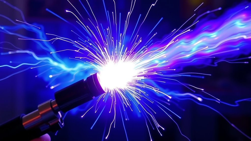
Plasma is commonly described as the fourth state of matter, after solids, liquids, and gases. It forms when enough energy separates some electrons from atoms or molecules. The result contains free electrons, positive ions, and often some neutral particles.
Those mobile charged particles make plasma electrically conductive. Unlike an ordinary gas, plasma responds strongly to electric and magnetic fields and can carry the current needed to sustain a cutting arc.
A plasma torch does not simply heat a stream of air with a flame. The power supply drives an electric arc through the gas, and the torch concentrates that energized flow into a small opening. This produces a much denser heat source than an unconstricted electrical arc.
The Electric Arc’s Role in Plasma Formation
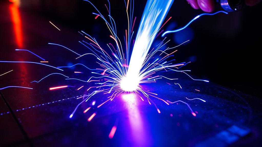
The electric arc supplies the energy that ionizes the gas and heats it to cutting temperature. In a typical DC transferred-arc cutter, the electrode inside the torch is negative and the workpiece becomes the positive side of the cutting circuit after transfer.
Pilot Arc vs. Main Cutting Arc
The pilot arc is a short starting arc inside the torch. It creates an initial conductive path through the gas. When the torch approaches a conductive workpiece connected to the work lead, the power supply detects transfer and directs the main current through the workpiece.
The main cutting arc carries substantially more energy than the pilot arc. It extends from the electrode, through the nozzle opening, and into the metal being cut.
Blowback and High-Frequency Starting
Modern handheld machines commonly use blowback starting. Gas pressure moves a spring-loaded electrode, briefly changing its contact with the nozzle and creating the pilot arc without a high-frequency spark.
Some older or specialized systems use high-frequency starting. A high-frequency electrical signal ionizes the gas between the electrode and nozzle. This method can create electromagnetic interference, so equipment manuals may require extra separation from computers, CNC controls, vehicle electronics, or communication equipment.
How the Arc Produces Cutting Heat
The narrow nozzle and gas flow concentrate the arc’s energy. According to Hypertherm’s plasma-technology overview, the plasma arc can approach 40,000°F. Actual temperatures vary across the arc and operating conditions, but the core is hot enough to melt conductive metal rapidly.
A plasma arc can approach 40,000°F, but heat alone does not make the cut—the gas stream must also carry the molten metal out of the kerf.
| Stage | What Happens |
|---|---|
| Ionization | Arc energy separates electrons from atoms and creates a conductive plasma path. |
| Arc transfer | The main current moves from the internal pilot circuit to the conductive workpiece. |
| Constricted heating | The nozzle concentrates the arc into a narrow region that melts the metal. |
| Metal removal | High-speed gas pushes molten metal through and out of the kerf. |
Key Components of a Plasma Torch System
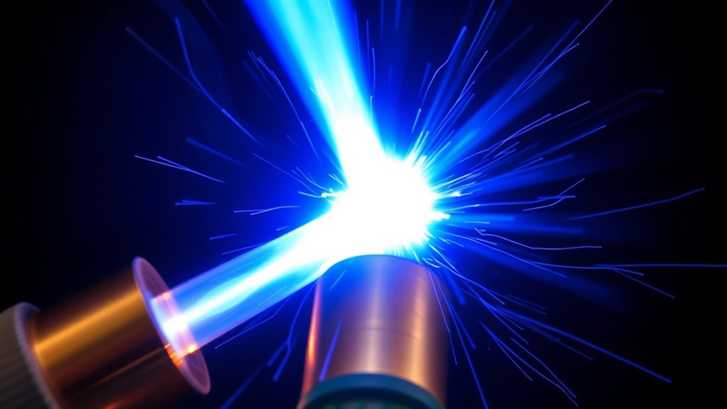
A complete plasma-cutting system includes more than the torch body. The power supply, gas source, work lead, controls, and replaceable consumables must work together.
| Component | Function |
|---|---|
| Power supply | Converts incoming electrical power into controlled DC output for starting and sustaining the arc. |
| Electrode | Carries current into the plasma arc. Many air-plasma electrodes contain a hafnium emitter. |
| Swirl ring | Distributes and rotates the gas, centers the arc, and electrically insulates specified torch parts. |
| Nozzle | Constrains the arc and gas through a precisely sized opening. |
| Shield or deflector | Protects the nozzle and controls the relationship between the torch and work surface. |
| Retaining cap | Holds the consumables in their designed positions and may direct cooling gas. |
| Gas supply and regulator | Provides gas at the pressure, flow, and quality required by the machine. |
| Work lead and clamp | Connects the conductive workpiece to the cutting circuit. |
Products Worth Considering

Package Include: 10 Shield Cups, 50 Nozzles, 20 Swirl Baffle, and 30 Electrodes.

[Achieve Precise Cuts] PT31 Plasma Cutting Consumables – Your Essential Tool for Efficient Cutting! Whether you're working with sheet metal, steel, or any other material, superior cutting performance ensure clean, accurate, and smooth cuts.

High-Quality Material:Made of high quality material to ensure a longer lifespan and superior performance.
Power Supply Functionality
The power supply changes AC input power into controlled DC output. It manages pilot-arc starting, current ramp-up, cutting amperage, arc transfer, and shutdown. Exact open-circuit voltage, load voltage, and starting circuitry vary by model, so they should be taken from the equipment manual rather than a generic voltage range.
Cutting capacity depends on more than the amperage printed on the front panel. Output voltage, power design, duty cycle, torch efficiency, consumables, gas delivery, material, and travel speed also affect performance.
Electrode and Nozzle Interaction
The electrode carries the arc, while the nozzle shapes it. The nozzle opening must remain round and undamaged. An enlarged, notched, or oval opening allows the arc to wander, which can create a wide kerf, excessive bevel, more dross, and unstable cutting.
The electrode also wears during normal use. Replace it according to the manufacturer’s inspection limit. Continuing to run a deeply pitted electrode can damage the nozzle or torch.
Gas Flow and the Swirl Ring
The swirl ring contains small passages that send gas around the electrode in a controlled pattern. This swirl helps center the arc in the nozzle, protects torch parts, and stabilizes the plasma column.
Gas flow also cools the torch during preflow, cutting, and postflow. Blocking postflow or switching off the air supply immediately after a cut can shorten consumable life.
What Gas Does a Plasma Torch Use?
Compressed air is the most common plasma gas for portable shop cutters. Industrial systems may use oxygen, nitrogen, argon-based mixtures, or separate plasma and shield gases. Only use gases and consumables approved for the specific machine and material.
| Gas | Typical Use | Important Consideration |
|---|---|---|
| Compressed air | General handheld cutting of mild steel, stainless steel, and aluminum. | Must meet the required flow and pressure and be clean, dry, and oil-free. |
| Oxygen | Mechanized cutting of mild steel on systems designed for oxygen. | Requires approved equipment, regulators, consumables, and strict oxygen cleanliness. |
| Nitrogen | Used by some systems for stainless steel, aluminum, and specialized processes. | Purity, pressure, and flow must match the manufacturer’s process chart. |
| F5 or argon-hydrogen mixtures | Specialized industrial cutting of stainless steel, high-alloy metals, or thicker nonferrous material. | Not suitable for machines that are not specifically designed and rated for the mixture. |
Why Air Quality Matters
Plasma-system manufacturers specify clean, dry, oil-free air because water and oil contamination disturb the arc and attack consumables. Poor air can cause sputtering, rapid electrode wear, an irregular nozzle opening, excess dross, and reduced cutting capacity.
A moisture separator near the machine can help, but humid shops or hard-working compressors may need additional filtration or a refrigerated or desiccant dryer. Never connect a plasma cutter downstream from an airline lubricator.
How to Size an Air Compressor
Do not choose a compressor by tank gallons alone. Find the plasma cutter’s required airflow and pressure in its manual, then compare those values with the compressor’s delivered CFM or SCFM at that pressure.
The compressor should maintain the required pressure while gas is flowing, not merely show adequate pressure before the trigger is pulled. A larger tank can provide a longer temporary reserve, but it cannot correct a pump that produces too little continuous airflow.
Note: If pressure drops as soon as cutting begins, the cause may be insufficient compressor output, a restricted filter, a small or excessively long hose, a leaking fitting, or a regulator that cannot flow enough air.
What Materials Can a Plasma Torch Cut?
A standard transferred-arc plasma cutter needs an electrically conductive workpiece because the main arc passes through the material. Common cuttable metals include:
- Mild steel and carbon steel
- Stainless steel
- Aluminum
- Copper
- Brass
- Expanded metal and other conductive metal shapes when the machine supports pilot-arc cutting
Standard shop plasma cutters cannot directly cut non-conductive materials such as wood, glass, ceramic, concrete, rubber, or plastic. Specialized thermal-plasma equipment may heat or process some non-conductive materials, but that is a different process and machine category.
Coated, Painted, and Contaminated Metal
Plasma may cut through paint, rust, or plating, but surface contamination can interfere with arc transfer and produce hazardous fumes. Attach the work clamp to clean, bare metal when possible.
Remove coatings from the cut area when safe and practical, identify unknown finishes before heating them, and use effective local exhaust. Galvanized, lead-painted, cadmium-plated, and other coated metals require special care. Stainless steel cutting can also generate hazardous chromium-containing fume.
Handheld vs. CNC and High-Definition Plasma
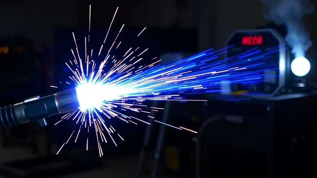
Handheld and mechanized plasma cutters use the same basic arc-and-gas principle, but their controls, precision, and intended workloads differ.
| Feature | Handheld Plasma | CNC or High-Definition Plasma |
|---|---|---|
| Torch movement | Controlled by the operator. | Controlled by a CNC gantry, robot, or track system. |
| Best use | Repair, demolition, fabrication, metal art, farm work, and field cutting. | Repeat parts, production cutting, detailed nests, bevels, and automated fabrication. |
| Cut consistency | Depends heavily on torch angle, standoff, and travel speed. | Uses programmed speed, automatic torch-height control, and repeatable motion. |
| Gas control | Usually compressed air with relatively simple controls. | May use automated pressure, flow, plasma-gas, and shield-gas settings. |
| Edge quality | Suitable for general fabrication when technique and settings are correct. | Can produce narrower kerfs, lower angularity, and more repeatable edges with a matched cutting table and process. |
High-definition plasma uses specialized torch geometry, gas control, consumables, motion, and software to increase arc-energy density and repeatability. It can produce substantially better edge and hole quality than basic handheld plasma, but results still depend on material, thickness, process settings, table motion, and maintenance.
Products Worth Considering

PROTECTS AGAINST RUST & CORROSION: Formulated for CNC plasma tables and water-table cutting systems. Use on ferrous and non-ferrous metals. Reduces flash rust on cut parts while protecting slats, tanks, and associated equipment.

𝐌𝐎𝐃𝐄𝐑𝐍 𝐓𝐄𝐂𝐇𝐍𝐎𝐋𝐎𝐆𝐘 𝐂𝐍𝐂 𝐏𝐋𝐀𝐒𝐌𝐀 𝐓𝐀𝐁𝐋𝐄: Craft your unique metal design arts with unparalleled precision with the Eastwood Versa-Cut 2'X2' CNC Plasma Table, a masterful blend of hobbyist accessibility and professional features. Crafted for those who demand perfection and a user-friendly metal fabrication experience. Designed specifically for use with Eastwood Versa-Cut 40 Plasma Cutter (𝐒𝐨𝐥𝐝 𝐒𝐞𝐩𝐚𝐫𝐚𝐭𝐞𝐥𝐲).

HIGH END TECHNOLOGY: The STV CNC Plasma Cutting Tables offer the best technology and high-quality components
Transferred vs. Non-Transferred Plasma Torches
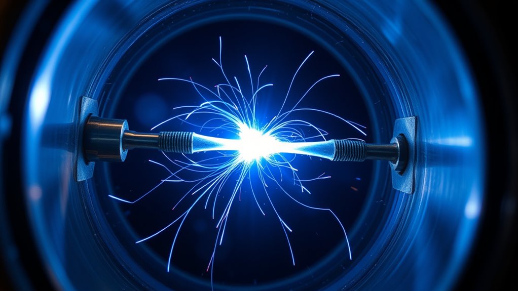
Transferred-Arc Plasma
In a transferred-arc torch, the main arc travels from the electrode through the plasma jet to the workpiece. The workpiece is part of the circuit, so it must conduct electricity.
This configuration transfers energy directly into the metal and is the process used by ordinary handheld and CNC plasma cutters. It is efficient for cutting, gouging, and marking conductive metal.
Non-Transferred Plasma
In a non-transferred torch, the arc remains between an electrode and an internal anode or nozzle. The hot plasma jet exits the torch, but the workpiece is not part of the electrical circuit.
Non-transferred thermal-plasma systems are used for applications such as plasma spraying, powder processing, heating, surface treatment, and waste treatment. Some can process non-conductive material, but they should not be confused with a standard shop plasma cutter and are not a general-purpose method for cutting wood, glass, or plastic.
Consumables, Maintenance, and Wear Signs
The electrode, nozzle, swirl ring, retaining cap, and shield must match the torch and selected amperage. Mixing incorrect parts can produce poor cuts, prevent the torch from starting, or damage the torch.
Signs That Consumables Need Attention
- A deep pit in the electrode emitter beyond the manufacturer’s limit
- An enlarged, oval, notched, or damaged nozzle opening
- Cracks, burns, blocked passages, or contamination on the swirl ring
- Heavy dross that remains after speed and amperage are corrected
- An arc that sputters, wanders, or repeatedly goes out
- Increasing cut bevel or a visibly wider kerf
- Reduced pierce capacity or slower cutting
Inspect consumables with the power disconnected and after the torch has cooled. Do not clean a precision nozzle opening with a drill bit, file, or object that can enlarge it. Replace damaged components with the correct manufacturer-approved parts.
Pro Tip: Before changing amperage or travel speed, check the air while it is flowing, place the work clamp on clean metal, and inspect the electrode and nozzle. Many apparent “setting problems” begin with restricted air, contamination, or worn consumables.
Common Plasma-Cutting Problems
| Problem | Likely Checks |
|---|---|
| No pilot arc | Input power, trigger lock, gas pressure, consumable installation, retaining cap, torch interlock, and machine fault indicators. |
| Pilot arc starts but will not transfer | Work-clamp contact, paint or rust under the clamp, torch distance, conductive material, work-lead damage, and machine capacity. |
| Heavy bottom dross | Travel speed, amperage, torch height, low airflow, worn consumables, and material thickness. |
| Excessive bevel | Torch angle, cutting direction, nozzle damage, standoff, travel speed, and whether the machine is operating near its maximum capacity. |
| Short consumable life | Wet or oily air, incorrect parts, repeated pilot-arc cycling, piercing too close to the plate, excessive piercing thickness, and interrupted postflow. |
| Arc stops during a cut | Compressor recovery, duty-cycle shutdown, loose work connection, excessive torch height, damaged consumables, or input-power drop. |
Plasma Torch Safety
OSHA identifies burns, eye damage, electric shock, ultraviolet radiation, metal fumes, and other physical hazards as major concerns during welding and thermal cutting. Your machine manual and workplace hot-work program take priority over general advice.
Protect Your Eyes, Face, Hearing, and Skin
- Wear safety glasses with side protection under an approved cutting shield or helmet.
- Use the filter shade specified for the machine’s amperage and process.
- Wear dry, flame-resistant gloves and clothing that cover exposed skin.
- Use hearing protection when noise levels require it.
- Protect nearby workers with suitable screens and warn them before starting the arc.
Control Fumes and Gases
Keep your head out of the fume plume and use local exhaust that captures fumes near the arc. General room ventilation may not be enough for stainless steel, galvanized metal, coated material, or confined spaces.
Do not use a respirator as a substitute for needed ventilation. Respirator selection requires a hazard assessment, correct filters or supplied air, fit testing where applicable, and compliance with workplace respiratory-protection requirements.
Prevent Fire and Explosion
- Remove flammable materials from the spark path or protect them with approved fire-resistant covers.
- Check the hidden side of walls, floors, partitions, and other surfaces before cutting.
- Maintain a fire watch when required.
- Never cut a closed or pressurized tank, drum, pipe, or container.
- Do not cut a container that held flammable, toxic, or reactive material unless a qualified procedure has made it safe.
- Never use plasma equipment where flammable gases, vapors, liquids, or combustible dust could ignite.
Prevent Electric Shock
- Keep gloves, clothing, the work area, and your body dry.
- Inspect the torch lead, work lead, power cord, and connectors before use.
- Replace damaged leads or broken connections rather than covering serious damage with tape.
- Disconnect input power before opening the machine or servicing the torch.
- Do not touch the torch tip, electrode, workpiece, or exposed electrical parts while the system is energized.
- Follow the manufacturer’s grounding instructions and all applicable electrical codes.
Handle Compressed Gas Safely
If the system uses cylinders, keep them upright and secured to a fixed support or suitable cart. Protect cylinder valves, use the correct regulator, keep hoses away from sparks and traffic, and remove faulty regulators from service rather than attempting an unauthorized repair.
For additional guidance, review Miller’s plasma-cutting safety guidance and the safety section of your equipment manual.
Applications and Advances in Plasma Cutting
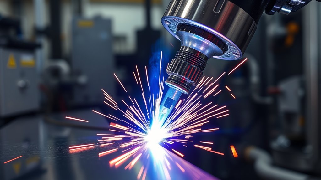
Plasma cutting is used in repair shops, construction, structural-steel fabrication, heavy-equipment maintenance, shipbuilding, manufacturing, HVAC work, metal art, and automated plate processing.
| Technology | Practical Benefit |
|---|---|
| CNC motion control | Repeats programmed shapes, speeds, lead-ins, and cut paths. |
| Automatic torch-height control | Maintains the specified pierce and cutting distance as plate height changes. |
| High-definition torch and nozzle designs | Create a narrower, more stable arc for improved angularity and repeatability. |
| Automated gas control | Sets and monitors plasma and shield-gas pressure and flow for the selected process. |
| Robotic cutting | Cuts three-dimensional parts and hard-to-reach features with programmed motion. |
| Cartridge-style consumables and automatic setup | Reduce assembly errors and simplify parameter selection on compatible newer systems. |
Advanced controls improve consistency, but they do not eliminate the need for clean gas, correct consumables, accurate process settings, effective fume control, and regular maintenance.
Frequently Asked Questions
How do plasma torches work?
A plasma torch sends gas through a narrow nozzle and energizes it with an electric arc. The gas becomes conductive plasma, the concentrated arc melts the metal, and the high-speed gas stream pushes molten material out of the kerf.
What materials cannot be cut with a standard plasma cutter?
A standard transferred-arc plasma cutter cannot directly cut non-conductive materials such as wood, glass, ceramic, rubber, concrete, or plastic. It needs an electrically conductive workpiece to complete the main cutting circuit.
Will a 20-gallon air compressor run a plasma cutter?
Possibly, but tank size alone does not answer the question. Compare the compressor’s delivered CFM or SCFM at the required PSI with the plasma cutter’s manual. The compressor must maintain the required pressure and flow while the torch is operating.
Does a plasma torch need gas?
Yes. The gas becomes the plasma, carries heat through the nozzle, ejects molten metal, and cools torch components. Portable systems commonly use compressed air, while specialized industrial systems may use oxygen, nitrogen, or approved gas mixtures.
Can a plasma torch cut aluminum and stainless steel?
Yes. Aluminum and stainless steel conduct electricity, so a correctly sized plasma cutter can cut them. Edge appearance, dross, gas choice, speed, and cut quality differ from mild steel, so use the manufacturer’s process chart.
What is the difference between a pilot arc and a cutting arc?
The pilot arc starts inside the torch between the electrode and nozzle. When it reaches conductive metal connected to the work lead, the main arc transfers to the workpiece and carries the cutting current.
Conclusion
A plasma torch works by combining a controlled DC arc with a focused, high-speed gas stream. The arc turns the gas into conductive plasma and melts the workpiece, while the gas clears molten metal from the kerf.
The basic principle is simple, but reliable cutting depends on the complete system: correct consumables, adequate clean and dry gas, a solid work connection, suitable amperage, steady torch movement, and proper maintenance. Just as importantly, every cut requires protection from electric shock, intense arc radiation, fire, molten metal, noise, and hazardous fumes.
Sources
- Hypertherm: Plasma Cutter Technology — plasma formation, arc temperature, conductive materials, and cutting process.
- Hypertherm: Plasma Cutter Starting Methods — blowback and high-frequency pilot-arc starting.
- Hypertherm: Power and Air Requirements — clean, dry, oil-free air and current equipment considerations.
- U.S. Department of Energy: DOE Explains Plasma — ionization, electrons, ions, and electrical conductivity.
- OSHA: Welding, Cutting, and Brazing Hazards — fume, radiation, shock, burn, and physical hazards.
- Miller Electric: Plasma Cutting Safety — electrical, fire, eye, fume, and compressed-gas precautions.