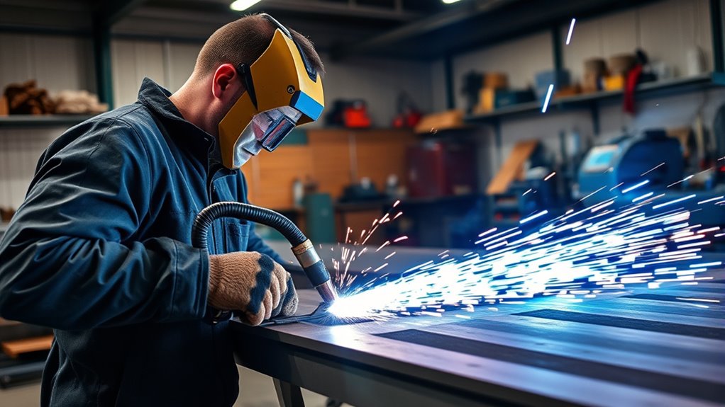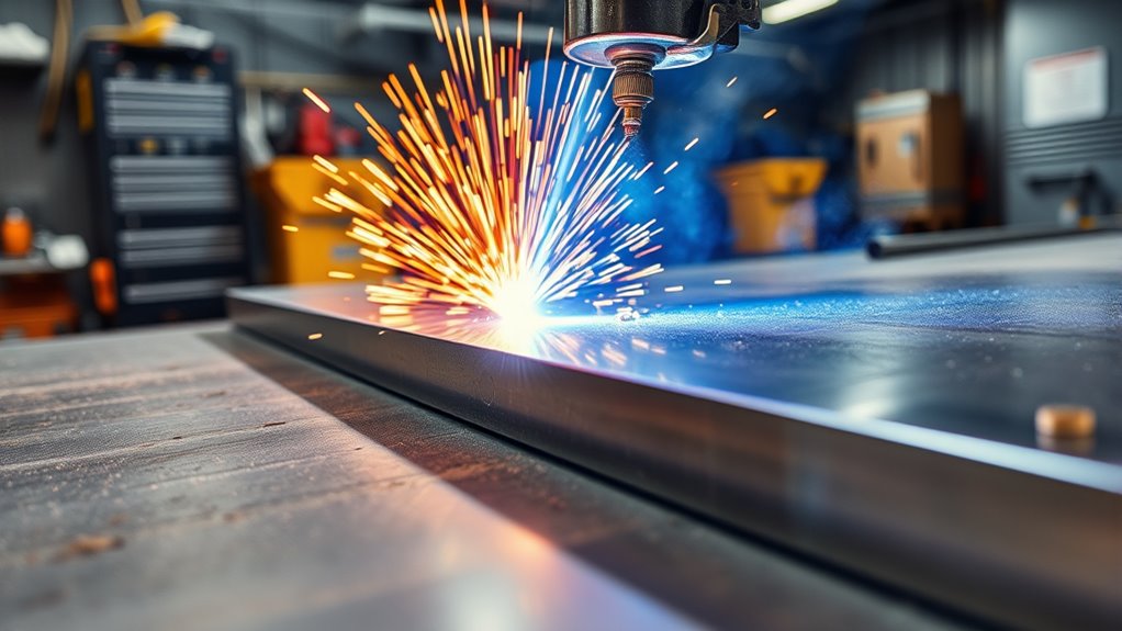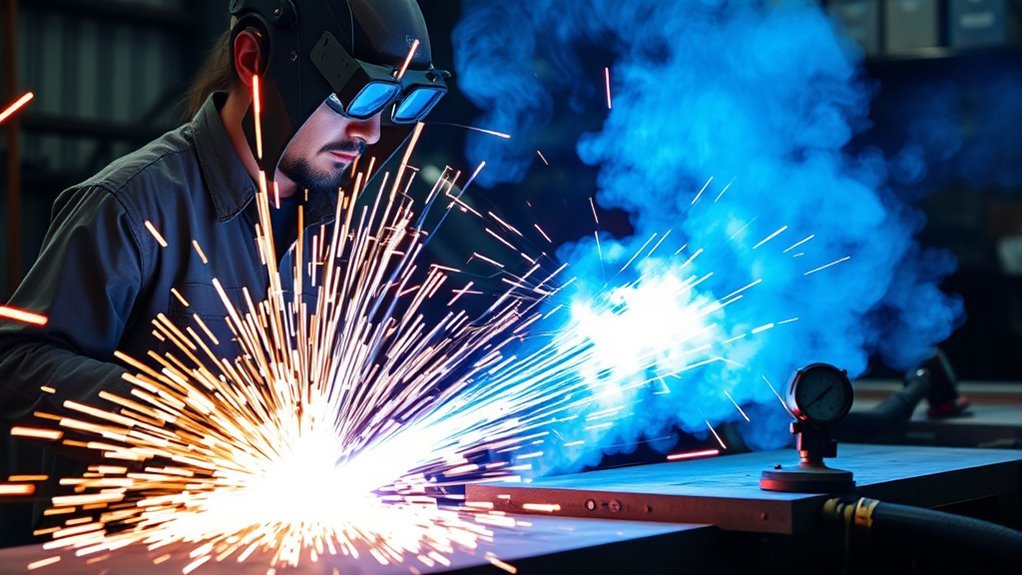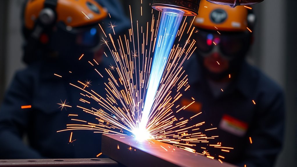
Plasma arc cutting may look dramatic, but the basic idea is simple: an electric arc turns a fast-moving gas into plasma, and that concentrated jet melts metal while the gas blows the molten material out of the cut. Good results depend less on guesswork than on matching the machine, consumables, gas, amperage, speed, and torch height to the material.
Quick Answer
Plasma arc cutting is a thermal process for electrically conductive metals. A power supply creates an arc that ionizes air or another gas into plasma. The hot, high-speed jet melts the workpiece and ejects the molten metal, producing fast cuts in steel, stainless steel, aluminum, copper, and other conductive materials.
Key Takeaways
- Standard plasma cutters work on electrically conductive metals, not wood, glass, masonry, or most plastics.
- Cut quality depends on the machine’s cut chart, including amperage, travel speed, torch height, gas type, gas pressure or flow, and the correct consumables.
- Recommended, production, pierce, and severance capacities mean different things; the highest advertised thickness is not usually the best-quality range.
- Arc light, electric shock, fire, fumes, hot metal, compressed gas, and noise are serious hazards that require proper PPE, ventilation, grounding, and work-area control.
At a Glance
| Time Required | Varies by setup and job; allow time for inspection, a test cut, and safe handling of hot parts. |
| Difficulty | Beginner to intermediate for straight handheld cuts; advanced for CNC setup, precision parts, bevels, and thick plate. |
| Tools Needed | A plasma cutter rated for the metal, correct consumables, specified air or process gas, work lead, PPE, ventilation, and a guide or CNC table when needed. |
| Cost | Operating costs include electricity, compressed air or process gas, consumables, and fume control; equipment cost varies widely with output and automation. |
Warning: A plasma arc can cause fatal electric shock, severe burns, eye injury, fire, explosion, hearing damage, and hazardous fume exposure. Read the operator manual, follow the machine’s safety labels and cut charts, and do not cut closed or unverified containers.
Understanding the basics of plasma arc cutting
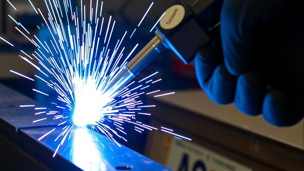
Plasma arc cutting is a thermal cutting method for electrically conductive materials. A power supply sends direct current through a torch. Gas passes through a small nozzle, becomes ionized, and forms a narrow plasma arc. The arc melts the workpiece, while the high-speed gas stream pushes molten metal out of the kerf.
The plasma arc can approach 40,000°F, but clean cutting comes from controlled energy, gas flow, speed, and torch height—not heat alone.
Most cutting systems use a transferred arc. In that arrangement, the workpiece becomes part of the electrical circuit. This is why the work lead needs a sound connection and why standard plasma cutting is limited to conductive materials.
Handheld plasma cutters are common in repair, fabrication, construction, and hobby shops. Mechanized systems add a CNC table, motion controls, torch-height control, and often automatic gas control. Both types can produce good results when the operator follows the manufacturer’s cut-quality guidance and the cut chart for the exact system.
Plasma generally creates a wider kerf and lower fine-detail accuracy than a well-matched laser process. However, it can be fast, versatile, and economical on many metal thicknesses. Unlike oxy-fuel, it can cut stainless steel, aluminum, copper, and other conductive nonferrous metals.
What materials can a plasma cutter cut?
A standard transferred-arc plasma cutter needs an electrically conductive path through the workpiece. Material type also affects gas choice, edge chemistry, dross, discoloration, and practical thickness capacity.
| Material | Suitability | Important notes |
|---|---|---|
| Mild or carbon steel | Excellent | Air is common for handheld work. Mechanized systems may use oxygen for faster, cleaner mild-steel cuts when the manufacturer specifies it. |
| Stainless steel | Excellent | Air works on many portable systems. Nitrogen, F5, or argon-hydrogen may be used on compatible multi-gas systems to control edge quality and color. |
| Aluminum | Excellent | Use the approved air, nitrogen, or specialty-gas process. Too much heat or the wrong speed can widen the kerf and round the top edge. |
| Copper, brass, and other conductive alloys | Usually suitable | Reflectivity is not the barrier it can be for some lasers, but high thermal conductivity may require more current and careful settings. |
| Galvanized, plated, painted, or coated metal | Cuttable with added controls | Coatings can produce hazardous fumes. Identify the coating, remove it from the cut zone when safe and practical, and use effective local exhaust ventilation. |
| Wood, glass, masonry, ceramic, and most plastics | Not suitable for standard transferred-arc cutting | These materials do not provide the electrical path required by a conventional plasma cutting arc. |
Note: Rust, mill scale, or paint may not prevent arc transfer, but they can weaken the work-lead connection and create fumes or poor edge quality. Clamp to clean, bare metal whenever possible.
The science behind plasma formation
Plasma is an ionized gas that contains free electrons, ions, and neutral particles. Because it contains charged particles, it can conduct electrical current. In a plasma cutter, electrical energy and a constricting nozzle turn the gas into a hot, fast, focused cutting jet.
Ionization of gas explained
The exact starting sequence depends on the machine. Some systems use a pilot arc, some use a blowback electrode, and older or specialized equipment may use a high-frequency starting circuit. The operator should not assume that every plasma cutter starts the same way.
- Gas begins to flow: Air, nitrogen, oxygen, argon-hydrogen, or another approved gas moves through the torch.
- The starting circuit creates an initial arc: The machine establishes an arc inside the torch or between the torch and workpiece, depending on its design.
- The gas ionizes: Energy from the arc separates some electrons from atoms, creating electrically conductive plasma.
- The cutting arc transfers: In a transferred-arc cutter, current flows from the electrode through the plasma to the workpiece.
- Metal melts and leaves the kerf: The concentrated arc melts the metal, and gas momentum blows the molten material through the plate.
Plasma jet characteristics
The nozzle constricts the arc, which raises its energy density and controls its shape. A swirl ring or similar gas-control component stabilizes the flow and centers the arc. The resulting jet combines very high temperature with high velocity.
Arc shape and energy density affect kerf width, edge angle, dross, and speed. A worn or damaged nozzle can shift the arc off-center, causing bevel or poor hole quality. This is why consumable condition matters as much as the amperage setting.
Key components of plasma cutting systems
A plasma system is more than a torch and power switch. Each part affects safety, arc stability, and cut quality.
Products Worth Considering
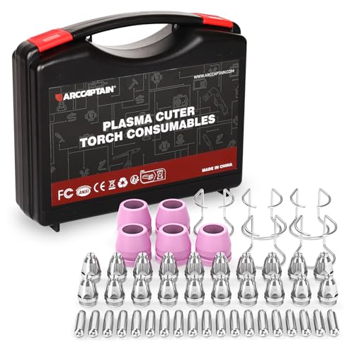
Package Include: 5 Shield Cups, 20 Nozzles .040", 5 Wire Spacer Guides, and 20 Electrodes.

Fit for : AG-60 AG-60P SG-55 WSD-60 Plasma cutter torch head

Package Include: 5 Shield Cups, 20 Nozzles .045", 5 Wire Spacer Guides, and 20 Electrodes.
Power supply functionality
The power supply converts incoming line power into controlled direct-current output for the plasma arc. The actual open-circuit and operating voltages vary by machine, so a single voltage range should not be treated as universal. Plasma equipment can contain lethal voltage even when the torch looks inactive.
Many modern portable systems use inverter electronics to reduce size and weight. Mechanized systems may add gas consoles, cooling systems, CNC interfaces, remote controls, and separate torch-height controls.
Torch design essentials
| Component | Function |
|---|---|
| Electrode | Carries current and contains an emitter selected for the process; many air- and oxygen-plasma torches use a hafnium emitter. |
| Swirl ring | Controls and shapes gas flow to center, cool, and stabilize the arc. |
| Nozzle | Constricts and directs the plasma arc through a precisely sized orifice. |
| Retaining cap | Holds the internal consumables in the correct position. |
| Shield or shield cap | Protects the nozzle and controls secondary gas flow or standoff on compatible torches. |
| Torch body and lead | Carry electrical power, gas, control signals, and coolant where a liquid-cooled design is used. |
Gas composition, amperage, travel speed, pierce height, and cut height are process settings rather than physical torch components. They must match the consumable set and material listed in the cut chart.
Setup checklist before plasma cutting
- Read the manual and cut chart: Confirm input power, duty cycle, material, thickness, consumable set, amperage, gas, pressure or flow, pierce height, cut height, and travel speed.
- Inspect the workpiece: Identify coatings, plating, sealed cavities, hidden flammables, and material on the far side of the cut. Never cut a closed, pressurized, or unverified container.
- Prepare the work area: Remove combustibles, control sparks, provide screens for bystanders, and arrange local exhaust ventilation so fumes move away from the breathing zone.
- Inspect the machine: Check the torch, lead, power cord, work lead, gas hose, regulator, and consumables. Replace damaged parts instead of improvising repairs.
- Verify the gas supply: Use only the gas and pressure or flow specified for the installed consumables. Shop air must meet the machine’s cleanliness, dryness, and flow requirements.
- Attach the work lead: Clamp it to clean, bare metal on the workpiece or cutting table as directed by the manufacturer.
- Put on PPE: Wear safety glasses with side protection under a suitable face shield or helmet, the correct filter shade, flame-resistant clothing, leather gloves, protective footwear, and hearing protection when required.
- Make a test cut: Use scrap of the same material and thickness. Check penetration, dross, bevel, and arc behavior before cutting the finished part.
Pro Tip: Start with the exact cut-chart values, not a generic online setting. Change only one variable at a time during a test cut so you can identify what improved or harmed the edge.
Products Worth Considering

Cutting Kit: Includes IPT40 electrode tips for CUT 55DS Pro and for CUT 65DS plasma cutting machines, ensuring accurate and efficient cutting performance.

Innovative Flip-Up Design: These Flip Safety Goggles feature classic flip-up styling that provides a versatile and convenient solution for eye . The shaded lens can effortlessly flip up and down, offering instant against high- light sources. Experience a practical and efficient design that ensures your eyes are shielded whenever needed, enhancing your safety and ease while working
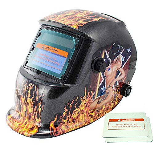
★【Larger Viewing Area Welding Hood】This welding helmet combines auto darkening filter with a 96mm x 48mm /3.8 x 1.9 inch viewing area, & 2 pcs extra welding helmet protective lens;
The plasma cutting process explained
Once the system is safely prepared, the cutting sequence is straightforward. The machine controls the arc and gas timing, while the operator or CNC motion system controls the path and travel speed.
- Position the torch: Hold it square to the plate for a straight cut. Use the drag, standoff, or mechanized height specified for the consumables.
- Start at an edge or use the approved pierce method: Edge starts reduce molten blowback. Piercing requires the correct pierce height, delay, and thickness limit.
- Trigger the start sequence: Gas flows and the machine establishes a pilot or starting arc according to its design.
- Transfer the main arc: The arc connects to the conductive workpiece and the cutting current rises to the selected value.
- Move at the charted speed: Keep the torch steady and square. The arc should fully penetrate while molten metal exits below the plate.
- Finish and allow post-flow: Release the trigger after leaving the cut. Do not interrupt any required gas post-flow, because it cools the torch and consumables.
- Handle the part safely: Assume the cut edge, slag, table slats, and offcuts are hot and sharp.
Note: Do not touch the nozzle to the work unless the installed consumables are designed for drag cutting. Some torches require a controlled standoff to prevent double arcing and nozzle damage.
Settings that control plasma cut quality
| Variable | What it affects | Common result when incorrect |
|---|---|---|
| Amperage | Arc energy and the usable thickness range for the installed consumables | Too low may fail to penetrate; too high for the nozzle or material can widen the kerf and shorten consumable life. |
| Travel speed | Heat input, arc angle, dross, and penetration | Too slow often creates heavy low-speed dross and a wider kerf; too fast can leave uncut areas or high-speed dross. |
| Cut height | Arc shape, voltage, bevel, and nozzle protection | Too high can increase bevel and reduce energy density; too low can damage consumables or cause double arcing. |
| Pierce height and delay | Protection from molten blowback and full plate penetration before motion | A low pierce or early movement can damage the nozzle and leave incomplete starts. |
| Gas type and quality | Arc chemistry, edge color, oxidation, speed, and consumable life | The wrong gas or wet, oily air can produce poor edges, unstable arcs, and early consumable failure. |
| Gas pressure or flow | Arc formation, cooling, and removal of molten metal | Incorrect supply can cause start failures, poor penetration, unstable cutting, or system faults. |
| Consumable condition | Arc centering and energy density | A worn nozzle or electrode can cause bevel, wide kerf, poor holes, excess dross, and inconsistent starts. |
| Torch angle and motion | Edge squareness and surface smoothness | A tilted or shaky torch produces uneven bevel and a rough cut face. |
Common plasma cutting problems and fixes
| Problem | Likely causes | What to check |
|---|---|---|
| Heavy dross on the bottom | Travel is too slow or too fast, amperage is mismatched, or consumables are worn. | Return to the cut chart, inspect the arc angle and consumables, and test speed in small steps. |
| Excessive bevel or angled edge | Torch is not square, cut height is wrong, nozzle is damaged, or motion is unstable. | Square the torch, verify height control, inspect the nozzle orifice, and confirm the correct cutting direction for the part. |
| Arc will not transfer | Poor work-lead contact, nonconductive work, heavy coating at the clamp, low gas supply, or incorrect consumable assembly. | Clamp to clean metal, verify gas and input power, and reinstall the correct parts in the proper order. |
| Arc stops during the cut | Travel is too fast, the arc is stretched, duty cycle is exceeded, gas supply drops, or the work connection is lost. | Check torch height, speed, fault indicators, compressor output, duty cycle, and work-lead connection. |
| Short consumable life | Wet or oily air, piercing too close, wrong pressure or flow, mismatched parts, or improper shutdown. | Service air filtration, use charted pierce settings, install genuine compatible parts, and allow the required post-flow. |
| Wide or wandering kerf | Worn nozzle, excessive current for the orifice, high torch position, or poor hand motion. | Replace damaged consumables, match the amperage to the nozzle, correct the standoff, and use a guide. |
| Incomplete penetration | Machine is undersized, speed is too high, amperage is too low, gas flow is wrong, or the material exceeds pierce capacity. | Use an edge start when permitted, reduce speed only within chart guidance, or select a higher-capacity process. |
Advantages and limitations of plasma cutting
Advantages
- Broad metal compatibility: It cuts ferrous and nonferrous conductive metals.
- Fast cutting: It can be highly productive on sheet, plate, expanded metal, and many repair jobs.
- No preheat for normal cutting: The arc reaches cutting temperature immediately.
- Handheld and automated options: The same core process works in portable shops, CNC tables, and robotic cells.
- Useful on imperfect surfaces: It can often cut rusty, painted, or galvanized metal, provided the work connection and fume controls are adequate.
- Multiple operations: Suitable consumables can support straight cutting, beveling, gouging, marking, flush cutting, and fine-feature work.
Limitations
- Conductive materials only: Standard transferred-arc systems cannot cut most nonmetals.
- Thermal effects: Plasma creates a heat-affected zone and can warp thin material when settings or sequence are poor.
- Lower fine-detail precision than laser: Kerf width, taper, and hole quality can be limiting for small features.
- Fumes, noise, and arc radiation: Proper extraction, PPE, screens, and hearing controls may be required.
- Consumable wear: Electrodes and nozzles are operating costs and directly affect quality.
- Utilities: Most systems require suitable electrical power and a clean, dry gas supply.
Selecting the right cutting method for your needs
No cutting process is best for every job. Choose based on material, thickness, tolerance, edge condition, production rate, heat sensitivity, portability, and total cost.
| Method | Best fit | Main trade-offs |
|---|---|---|
| Plasma | Conductive metals; portable repairs; general fabrication; medium and thick plate; CNC production | Fast and versatile, but creates heat, fumes, kerf, and some edge taper. |
| Laser | Fine detail, small holes, tight tolerances, and high-volume thin-to-medium sheet work | High precision and narrow kerf, but usually higher capital cost and process limits that depend on laser power and material. |
| Waterjet | Heat-sensitive parts, thick materials, mixed materials, stone, composites, and jobs that must avoid a heat-affected zone | No thermal HAZ, but cutting may be slower and abrasive handling and maintenance add cost. |
| Oxy-fuel | Thick carbon and low-alloy steel, field work, heating, and jobs where electrical power is limited | Does not cut stainless steel or aluminum like plasma, needs fuel-gas controls, and usually creates more heat and a wider kerf. |
| Mechanical saw, shear, or abrasive wheel | Straight cuts, small shops, nonconductive materials, and low-volume work | Simple equipment, but geometry, speed, blade wear, sparks, and access can limit the job. |
CNC plasma improves repeatability and motion control, but the table cannot compensate for the wrong consumables, damaged torch parts, poor gas, or an incorrect process. For tight-tolerance work, compare the required tolerance with sample parts from the exact machine and material rather than relying on a general accuracy claim.
Common gases used in plasma cutting
Use only gases and combinations approved for the power supply, torch, consumables, material, and thickness. Portable air-plasma machines often use one gas. Industrial systems may use separate plasma and shield gases.
| Gas or mixture | Typical use | Important limits |
|---|---|---|
| Clean, dry air | General-purpose cutting of mild steel, stainless steel, and aluminum on compatible air-plasma systems | Affordable and convenient, but moisture, oil, or inadequate flow harms quality and consumable life. Air can leave oxidized edges. |
| Oxygen | Mechanized mild-steel processes designed for oxygen plasma | Can improve speed and edge quality on mild steel. Use only approved oxygen-clean equipment and the listed consumables. |
| Nitrogen | Stainless steel, aluminum, and selected shield-gas processes | Results depend on the paired shield gas, amperage, and torch design. |
| Argon-hydrogen | Thicker stainless steel, aluminum, and high-alloy metals on compatible multi-gas systems | Specialized and more expensive; hydrogen mixtures require strict gas-system and ventilation controls. |
| F5 or other hydrogen-nitrogen mixtures | Selected stainless-steel processes on approved equipment | Not a universal substitute for air or nitrogen. Follow the exact manufacturer process. |
A manufacturer’s plasma gas selection guide can explain the trade-offs, but the machine-specific cut chart remains the controlling source for setup.
How to read plasma cutter capacity ratings
Thickness claims are easy to misunderstand because manufacturers use several ratings. Compare machines using the same rating and the same material.
- Recommended cut capacity: A thickness the system can cut at a useful speed with expected quality under stated conditions.
- Production capacity: A continuous-use or duty-cycle-based rating for repeat work. The exact definition is manufacturer-specific.
- Pierce capacity: The maximum thickness the torch can start in the middle of the plate using the approved pierce sequence.
- Edge-start capacity: A thicker plate may be cut by beginning at the edge even when it cannot be pierced safely.
- Severance capacity: The machine can separate the metal, usually at low speed and with reduced edge quality. This is not the preferred everyday cutting range.
Note: Plasma thickness capacity depends on amperage, torch and consumable design, material, gas, speed, pierce method, duty cycle, and the edge quality you will accept. There is no single universal “best” thickness range.
Safety measures and best practices in plasma cutting
Plasma cutting combines high voltage, intense arc radiation, molten metal, sparks, fumes, compressed gas, and noise. The operator manual and workplace rules take priority over general guidance.
Protect your eyes, face, skin, and hearing
Wear safety glasses with side protection beneath a face shield or cutting helmet. Select the filter shade for the actual arc current and visibility. The OSHA eye-and-face protection table lists minimum shades of 8 for plasma arc cutting below 300 amps, 9 for 300–400 amps, and 10 for 400–800 amps when the arc is clearly seen. Never go below the applicable minimum; also follow the machine manual and site rules.
Cover exposed skin with dry, flame-resistant clothing. Wear leather gloves and suitable protective footwear. Plasma cutting can exceed acceptable noise levels, so use hearing protection when exposure measurements, the manual, or workplace rules require it.
Control fumes and coatings
Keep your head out of the plume and use local exhaust ventilation at or near the arc. Water tables and downdraft tables can help on mechanized systems, but they do not remove the need for a proper exposure assessment.
Identify paint, plating, galvanizing, lead, cadmium, chromium, nickel, and other hazardous constituents before cutting. Remove coatings from the cut area when safe and practical. Cutting indoors or in confined spaces may require mechanical ventilation, respiratory protection, atmospheric testing, and a formal confined-space program. Follow OSHA welding, cutting, and brazing requirements and applicable local rules.
Prevent fire and explosion
Move combustibles away or protect them with fire-resistant covers. Inspect the opposite side of walls, floors, partitions, and enclosed structures because sparks can travel through gaps and ignite hidden material. Keep an appropriate fire extinguisher nearby and use a fire watch when required.
Warning: Never cut a closed or pressurized tank, drum, pipe, or container. Do not cut a container that held flammable, toxic, or reactive material unless a qualified procedure has made it safe and verified its condition.
Avoid electric shock
Keep the work area, gloves, clothing, leads, and torch dry. Do not cut in rain or standing water unless the equipment and procedure are specifically designed and approved for that environment. Inspect insulation and connections before use. Disconnect and lock out power before opening the power supply or servicing internal components.
Attach the work lead as directed and maintain the equipment grounding required by the manufacturer and electrical code. A work lead is part of the cutting circuit; it does not replace protective equipment grounding.
Handle compressed gas safely
Secure cylinders upright, protect valves, use the correct regulators and fittings, and keep hoses away from sparks, traffic, and sharp edges. Never repair a regulator or seal a damaged hose with tape. Remove defective gas equipment from service.
Maintain the torch and consumables
Turn off and isolate power before disassembling the torch. Install only compatible parts in the specified order. Inspect the electrode pit, nozzle orifice, swirl ring, shield, retaining cap, and O-rings. Replace worn parts as a matched set when the manual calls for it.
Innovations and current trends in plasma technology
Modern plasma systems focus on more consistent cut quality, easier setup, longer consumable life, better process control, and closer integration with CNC software.
- High-definition and precision plasma: Tighter arc constriction, controlled gas delivery, and advanced consumables reduce bevel and kerf width compared with conventional plasma.
- Inverter power supplies: Portable systems use compact power electronics to reduce size and improve control.
- Automatic parameter selection: Some systems and CNC software load amperage, gas, speed, pierce height, cut height, and timing from digital cut charts.
- Improved torch-height control: Better sensing and motion control help keep the arc at the intended height despite plate movement or warping.
- Connected diagnostics: Industrial systems increasingly record faults, consumable data, process settings, and maintenance information for troubleshooting and production control.
- Application-specific consumables: Fine-feature, gouging, flush-cutting, extended-reach, marking, and robotic consumables expand what one power supply can do.
These systems can narrow the performance gap with laser cutting in some applications, but process choice still depends on feature size, tolerance, material, thickness, edge requirements, production volume, and budget.
Glossary
- Plasma
- An ionized gas containing charged particles that can conduct electricity.
- Kerf
- The width of material removed by the cutting process.
- Dross
- Molten metal that resolidifies on the lower edge of the cut.
- Heat-affected zone (HAZ)
- The area beside the cut that is heated enough to change the metal’s structure or properties without fully melting.
- Pilot arc
- A starting arc established by the torch before or during transfer of the main cutting arc to the workpiece.
- Transferred arc
- An arc in which current passes from the torch electrode through the plasma to the conductive workpiece.
- Consumables
- Replaceable torch parts such as the electrode, nozzle, swirl ring, retaining cap, and shield or cartridge.
- High-tolerance or high-definition plasma
- A refined plasma process that uses tighter arc constriction, advanced gas control, and coordinated motion to improve edge quality and accuracy.
Frequently Asked Questions
What is the process of plasma arc cutting?
A power supply creates an electric arc that ionizes a flowing gas. The nozzle constricts the ionized gas into a hot, high-speed plasma jet. The arc melts conductive metal, and the gas ejects the molten material from the kerf. Amperage, speed, gas, consumables, and torch height are matched through the machine’s cut chart.
What are the two primary types of plasma arc cutting?
For equipment selection, plasma cutting is commonly grouped into conventional plasma and precision or high-definition plasma. Conventional systems serve general handheld and mechanized work. Precision systems use tighter arc and gas control for cleaner, more accurate automated cuts. Arc configuration is a separate classification: metal cutting normally uses a transferred arc, while non-transferred torches are more common in heating and spraying processes.
What is the plasma arcing method?
The plasma arcing method uses electrical energy to ionize a gas and create a conductive arc. In transferred-arc cutting, current flows through the plasma to the workpiece. The concentrated arc supplies heat, while the gas stream removes molten metal. Starting methods vary by machine and may include pilot-arc, blowback, contact, or high-frequency designs.
What are the disadvantages of plasma arc cutting?
Plasma cutting creates arc radiation, noise, fumes, sparks, molten metal, a kerf, and a heat-affected zone. It is limited to conductive materials and usually cannot match laser cutting for the smallest features or waterjet cutting where no thermal effect is allowed. It also needs electrical power, gas, ventilation, and replaceable consumables.
Can a plasma cutter cut any metal?
It can cut most electrically conductive metals, including mild steel, stainless steel, aluminum, copper, and brass, when the system has enough capacity and the correct process. Material composition, thermal conductivity, thickness, gas choice, and the desired edge quality still affect the result.
Why does a plasma cut leave dross?
Dross forms when molten metal is not fully expelled and then freezes on the lower edge. Common causes include travel speed that is too slow or too fast, wrong amperage, incorrect cut height, poor gas supply, worn consumables, or a process that is outside the system’s rated range.
Is it safe to plasma cut painted or galvanized metal?
The metal may be cut, but the coating can create hazardous fumes. Identify the coating first, remove it from the cut area when safe and practical, and use effective local exhaust ventilation. Lead-, cadmium-, chromium-, and zinc-containing materials may require additional exposure controls, respiratory protection, or professional assessment.
Related articles
Conclusion
Plasma arc cutting uses a controlled electrical arc and gas flow to melt and remove conductive metal. The process can be fast and flexible, but the machine’s cut chart—not a universal speed, pressure, voltage, or thickness rule—determines the correct setup.
Start with clean gas, sound consumables, a secure work connection, the specified torch height, and a test cut. Then protect yourself from voltage, arc light, sparks, fumes, hot metal, and noise. With those controls in place, plasma cutting becomes a repeatable fabrication process rather than a trial-and-error tool.
Sources
- Hypertherm: What Is a Plasma Cutter? — process basics, conductive materials, plasma temperature, handheld and mechanized systems.
- Hypertherm: Understanding Plasma Cutting Attributes — material compatibility, capacity variables, consumables, automation, and operating factors.
- Hypertherm: Plasma Gas Selection Guide — air, oxygen, nitrogen, argon-hydrogen, and shield-gas selection.
- OSHA 29 CFR 1910.133: Eye and Face Protection — minimum filter shades for plasma arc cutting.
- OSHA 29 CFR 1910.252: Welding, Cutting, and Brazing — fire prevention, ventilation, PPE, and coated-metal controls.
- Miller Electric: Plasma Cutting Safety Makes Sense — electric shock, compressed gas, coatings, containers, fire, and fume precautions.