I burned through a thin sheet of stainless because I did not fully understand how gauge thickness worked. My MIG welder was running, the filler wire was loaded, and the joint looked ready, but I had selected settings for material that was much thicker than the sheet in front of me. That mistake taught me that knowing the actual metal thickness matters as much as joint preparation, filler selection, and torch control.
Gauge numbers can feel backward because a higher number usually means thinner material. The bigger trap is that the same gauge number does not equal the same thickness in carbon steel, stainless steel, aluminum, galvanized sheet, and wire. You have to know both the material and the gauge system before selecting a welding process or machine setting.
Quick Answer
Gauge thickness is a material-specific numbering system used for sheet and wire. Within one system, a larger gauge number normally means thinner metal. However, 16-gauge carbon steel, stainless steel, and aluminum have different nominal thicknesses, so always confirm the material and measure the sheet in inches or millimeters before welding.
Key Takeaways
- Higher gauge numbers usually mean thinner material, but only within the same gauge system.
- Carbon steel, stainless steel, aluminum, galvanized sheet, and wire use different conversion tables.
- Use a micrometer or caliper to confirm actual thickness instead of trusting appearance or an unknown label.
- Set the welder from the measured thickness, machine chart, filler, gas, joint, and welding position—not gauge alone.
- Gauge does not determine whether a trailer, guardrail, pressure vessel, or other load-bearing part is structurally safe.
At a Glance
| Time Required | About 5–10 minutes to identify the material, measure several points, and compare the result with the correct chart |
| Difficulty | Easy for clean, accessible sheet; moderate when coatings, corrosion, curves, or unknown alloys are involved |
| Tools Needed | Micrometer or digital caliper, material-specific gauge chart, cleaning cloth, and matching scrap for a test weld |
| Cost | No added cost when measuring tools are already available; otherwise, the measuring tool is the main expense |
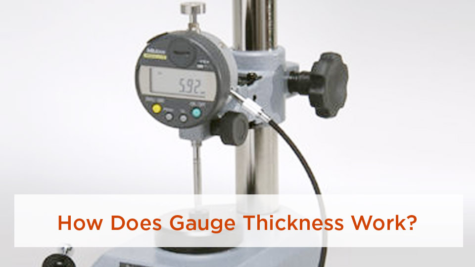
Image credit: DirectIndustry.
What Is Gauge Thickness in Welding?
Gauge thickness is a numbered size used for certain sheet-metal and wire products. The number is a reference to a table, not a direct measurement. You cannot calculate every sheet thickness by applying one simple formula to the gauge number.
Within a specific table, the numbering normally runs backward: a low gauge number identifies thicker material, while a high gauge number identifies thinner material. For example, common Manufacturers’ Standard Gauge values put 10-gauge carbon steel at about 0.1345 inch and 20-gauge carbon steel at about 0.0359 inch.
A gauge number is incomplete unless you also know the material and gauge system.
That distinction matters because nominal 16-gauge carbon steel is about 0.0598 inch, 16-gauge stainless steel is about 0.0625 inch, and 16-gauge aluminum is about 0.0508 inch. Selecting a welding setting from “16 gauge” without identifying the metal can put too much or too little heat into the joint.
Note: Welding electrodes are normally specified by their actual diameter, such as 3/32 inch or 1/8 inch, and by their classification. Do not assume a sheet-metal gauge chart applies to an electrode.
Why Do Higher Gauge Numbers Mean Thinner Metal?
The backward numbering comes from several old manufacturing systems rather than one universal standard. Some early wire gauges roughly followed the successive reductions made while drawing wire. American Wire Gauge, also called Brown & Sharpe gauge, was later organized as a mathematical progression of wire diameters.
Sheet-metal gauges developed through separate weight and thickness tables. The federal United States Standard Gauge for sheet and plate iron and steel was established by an 1893 law. That USSG table is not identical to the Manufacturers’ Standard Gauge table commonly used for commercial carbon-steel sheet.
The historic mix of systems is why “14 gauge” can refer to different actual dimensions. The old National Bureau of Standards wire-gauge guidance documented the confusion and recommended specifying actual dimensions for precise work.
Pro Tip: Put the decimal thickness and material grade on drawings and purchase orders. “0.0598-inch carbon-steel sheet” communicates more clearly than “16 gauge” by itself.
Gauge Systems You May Encounter
- Manufacturers’ Standard Gauge (MSG): Commonly referenced for uncoated carbon-steel sheet.
- United States Standard Gauge (USSG): A federal table for sheet and plate iron and steel. Its values differ from MSG.
- Stainless-steel gauge: Uses nominal thicknesses that differ slightly from common carbon-steel MSG values.
- American Wire Gauge (AWG/Brown & Sharpe): Primarily a wire-diameter system, though AWG values are also used in some nonferrous sheet references.
- Galvanized-sheet conventions: May account for the steel substrate and zinc coating differently. Confirm the supplier’s specified base-metal thickness and coating designation.
Metric markets and modern engineering drawings often avoid gauge altogether and state thickness directly in millimeters. That approach removes uncertainty and makes tolerance control easier.
Gauge Thickness Chart for Common Welding Materials
The values below are common nominal reference values. They are not guaranteed measurements for every delivered sheet. Product tolerances, coatings, specification requirements, and supplier conventions can produce small differences.
| Gauge | Carbon Steel (in/mm) |
Stainless Steel (in/mm) |
Aluminum (in/mm) |
|---|---|---|---|
| 10 | 0.1345 / 3.42 | 0.1406 / 3.57 | 0.1019 / 2.59 |
| 12 | 0.1046 / 2.66 | 0.1094 / 2.78 | 0.0808 / 2.05 |
| 14 | 0.0747 / 1.90 | 0.0781 / 1.98 | 0.0641 / 1.63 |
| 16 | 0.0598 / 1.52 | 0.0625 / 1.59 | 0.0508 / 1.29 |
| 18 | 0.0478 / 1.21 | 0.0500 / 1.27 | 0.0403 / 1.02 |
| 20 | 0.0359 / 0.91 | 0.0375 / 0.95 | 0.0320 / 0.81 |
These comparisons show why the material name cannot be left out. A 10-gauge aluminum sheet is noticeably thinner than 10-gauge carbon steel or stainless steel.
Note: Galvanized steel should not automatically be treated as bare carbon steel of the same stated gauge. Confirm the substrate thickness, zinc-coating designation, and total measured thickness with the supplier.
Why Gauge Thickness Matters in Welding Projects
Thickness affects how quickly the joint heats, how much current the process needs, how easily the material distorts, and what joint preparation may be required.
Heat Input and Burn-Through
Thin sheet has little mass to absorb heat. Excess voltage, amperage, wire feed, arc time, or slow travel can melt the joint edge before a stable bead forms. Tight fit-up, small wire, short welds, and time for cooling help control burn-through.
Fusion and Penetration
Heavier material can hide lack of fusion beneath a bead that looks acceptable from the surface. The process needs enough energy to melt both joint faces and tie the filler into the base metal. Joint angle, root access, cleanliness, electrode position, travel speed, and welding procedure all matter.
Distortion
As a weld cools, the metal contracts. Thin panels move more easily, so poor sequencing can pull a flat panel into a wave or twist an enclosure out of square. Tacks, clamps, skip welding, balanced sequencing, and backing bars can reduce movement.
Strength and Design
Thickness affects load capacity, but it is only one design variable. A formed channel and a flat strip of the same gauge behave differently. Material grade, shape, span, holes, corrosion, fatigue, weld size, and load direction also change the result.
Warning: Do not select material for a trailer frame, lifting device, guardrail, vehicle suspension part, pressure vessel, fuel system, or other safety-critical assembly from a gauge chart alone. Follow approved drawings, rated plans, the governing code, and a qualified welding procedure where required.
How to Measure Gauge Thickness Accurately
A micrometer is usually the best tool for thin sheet because its spindle applies controlled pressure over a small measuring face. A digital caliper is useful for quick shop checks, but jaw alignment and hand pressure can affect the reading.
- Identify the material. Determine whether the part is carbon steel, stainless steel, aluminum, galvanized steel, or another alloy. A magnet may help separate some materials, but it cannot identify the exact grade.
- Find a safe measuring point. Use a clean, straight edge that is free of burrs, weld reinforcement, folds, or severe corrosion.
- Check the measuring tool. Clean the measuring faces, close the tool gently, and confirm that it reads zero.
- Measure at several locations. Take at least three readings and compare them. Variation can reveal taper, coating buildup, corrosion, or damaged edges.
- Compare the decimal reading with the correct chart. Match both the material and gauge system. Record the actual inch or millimeter value for setting up the welder.
- Run a test weld. Use scrap of the same material, thickness, coating condition, and joint design before welding the finished part.
Warning: Do not grind, sand, heat, or weld an unknown coating merely to obtain a measurement. Lead paint, cadmium plating, zinc coatings, chromium-containing materials, and other finishes can create serious exposure hazards. Identify the coating and review its safety information first.
Measuring Painted, Rusty, or Coated Sheet
Paint, powder coating, galvanizing, rust, and mill scale can make the measured value larger than the base-metal thickness. Use an uncoated edge, supplier documentation, an ultrasonic thickness gauge suited to the material, or another approved method when removing the coating would be unsafe or would damage the part.
Do not squeeze a soft aluminum edge so firmly that the tool dents it. Close the micrometer or caliper until the faces make consistent contact, then stop.
Using a Slotted Sheet-Metal Gauge
A slotted gauge tool is fast for identifying common clean sheet sizes. Slide the edge into the slot that fits without force. Confirm that the tool is marked for the correct material system; a steel-only gauge tool can give the wrong answer on aluminum or stainless.
Choosing the Right Thickness for Your Welding Application
Start with the finished part’s requirements rather than asking which gauge is “strong enough” in isolation.
- Load: Determine static, impact, vibration, fatigue, and accidental loads.
- Part shape: Tube, angle, channel, corrugations, bends, and ribs can add stiffness without simply increasing thickness.
- Material grade: Two sheets of equal thickness can have different yield strength, ductility, corrosion resistance, and weldability.
- Environment: Moisture, salt, heat, chemicals, and abrasion may require corrosion allowance or a different alloy.
- Manufacturing process: Consider whether the part must bend, stamp, roll, machine, weld, grind, or accept fasteners.
- Applicable requirements: Follow drawings, customer specifications, building rules, transportation requirements, or welding codes that apply to the project.
For a decorative enclosure, fire-pit shell, or nonstructural skin, thinner sheet may reduce weight and make forming easier. Frames, hitches, lifting points, pressure boundaries, and vehicle structures require a documented design rather than a rule of thumb.
Welding Techniques for Different Gauge Thicknesses
Thin Sheet
Thin steel sheet is commonly welded with short-circuit MIG, TIG, or another low-heat process suitable for the alloy. Miller’s sheet-metal welding guidance recommends small-diameter MIG wire—often 0.023 or 0.024 inch—for light-gauge work.
- Keep the joint fit tight and consistent.
- Use the smallest suitable filler diameter.
- Make short, separated tacks or skip welds rather than one long continuous pass.
- Move around the part so heat does not build in one area.
- Use a clean copper or aluminum backing bar when suitable.
- Let the panel cool naturally between welds.
Medium Sheet and Light Plate
As thickness increases, the process can accept more heat and deposition, but the correct parameters still depend on the machine and joint. Follow the door chart, manual, filler data, or welding procedure. Check the bead for good toe tie-in, stable profile, and fusion into both pieces.
Heavier Material
Heavier material may require a larger power source, multiple passes, joint beveling, root access, preheat, or controlled interpass temperature. Those decisions come from the alloy, thickness, restraint, hydrogen-cracking risk, service, and welding procedure—not a gauge number by itself.
Pro Tip: Record a successful setup by material, actual thickness, wire or electrode, gas, polarity, joint, position, voltage, wire feed or amperage, and travel technique. That record is far more useful than remembering only the gauge.
Common Gauge and Welding Mistakes
Assuming Every Material Uses the Same Chart
Nominal 16-gauge aluminum is about 0.0508 inch, while common 16-gauge carbon steel is about 0.0598 inch. The difference is meaningful, but aluminum is not “half as thick.” Label offcuts and store different alloys separately.
Measuring Over Coating or Corrosion
A coating adds to the measured dimension, while corrosion can create both buildup and metal loss. Measure a representative clean edge or use product documentation rather than guessing from one damaged spot.
Selecting Settings from Gauge Alone
Two pieces with the same gauge can need different setups because of alloy, joint type, position, shielding gas, wire size, fit-up, and heat sinking. Begin with the machine manufacturer’s recommended range and adjust on matching scrap.
Confusing Porosity with Excess Heat
Pinholes and bubbles usually point toward contamination or shielding problems, while burn-through and an oversized fluid puddle point toward excessive heat or arc time. The correction depends on the symptom.
Treating Gauge as a Structural Rating
A gauge chart tells you nominal thickness. It does not tell you the allowable load, required weld size, fatigue life, or factor of safety.
Troubleshooting Weld Problems by Symptom
| Symptom | Likely Causes | Checks and Corrections |
|---|---|---|
| Burn-through | Excess heat, long arc time, wide gap, slow travel, oversized filler | Verify thickness; lower the appropriate setting within the machine’s range; tighten fit-up; use smaller wire; shorten weld time; add a backing bar |
| Warping | Too much concentrated heat, poor sequencing, weak clamping | Use more tacks, skip around the part, balance welds, shorten passes, and allow cooling |
| Porosity or pinholes | Oil, moisture, paint, coating, wind, gas leak, poor nozzle coverage, wrong polarity | Stop and clean safely; inspect the gas system; shield the arc from drafts; verify gas, polarity, flow, and stickout |
| Cold-looking convex bead | Insufficient wire-feed current, voltage mismatch, excessive stickout, poor work angle | Return to the manufacturer’s chart; correct stickout and angle; increase the appropriate parameter gradually on scrap |
| Undercut or overly flat bead | Excess voltage, heat, travel speed, or poor angle | Reduce the responsible parameter, correct the torch angle, and verify travel speed |
| Surface bead with poor fusion | Insufficient heat at the joint faces, excessive speed, contamination, poor access, wrong angle | Improve cleaning and joint preparation; direct the arc into both members; correct speed and settings; add passes only when the procedure allows |
Tools and Equipment for Different Gauges
- Micrometer: Best for accurate thin-sheet measurements.
- Digital or dial caliper: Convenient for fast checks, edge dimensions, and thicker parts.
- Material-specific slotted gauge: Fast for clean stock when the gauge system is known.
- Fillet-weld gauge: Checks weld-leg size, throat-related dimensions, and profile where the applicable acceptance criteria require them.
- Copper or aluminum backing bar: Supports a thin joint and draws heat away when compatible with the work.
- Clamps and fixtures: Hold fit-up and control distortion.
- Shears, nibblers, saws, and plasma cutters: Choose the cutting method from the actual thickness and cut-quality requirement.
- Deburring tools: Remove sharp edges and burrs without unnecessarily thinning the joint.
A machine’s advertised maximum thickness does not guarantee a sound weld in every joint or position. Input power, duty cycle, transfer mode, consumable, preparation, and operator skill all affect usable capacity.
Products Worth Considering

7piece Fillet Weld Set Gage Rl Gauge

【7 pieces Weld Fillet Gauges】: 7 pieces weld fillet gauges are held by bolt and nut that can be disassembled, each weld gauge can be used to check the size of fillet legs and fillet throats

Durable: Made of high-quality 304 stainless steel, this gauge set has great rust resistance and wear resistance.
Safety When Welding Different Gauges and Materials
Gauge changes heat behavior, but the most serious hazards often come from the alloy, coating, cleaner, work area, and part history.
Galvanized and Coated Steel
Heating zinc and other coatings can produce hazardous fumes. Remove coatings from the weld area only when the removal method is approved and the resulting dust or debris is controlled. Position local exhaust close enough to capture the plume, keep your head out of the fumes, and follow workplace exposure requirements.
Stainless Steel
Welding stainless and other chromium-containing alloys can generate hexavalent chromium. OSHA identifies welding on stainless and alloy steel as an important source of occupational Cr(VI) exposure. Shielding gas selection does not replace source extraction, exposure assessment, or required respiratory protection.
Solvents and Surface Cleaners
Remove grease, oil, paint, moisture, and other contamination using a cleaner that is compatible with the material and welding process. Keep flammable cleaners and vapors away from hot work, allow the surface to dry completely, and never use chlorinated solvent residue near an arc because heat and ultraviolet radiation can create highly toxic decomposition products.
Fire Prevention
The OSHA welding standard requires combustibles to be moved or protected and calls for a fire watch under specified hazardous conditions. Where required, the watch must continue for at least 30 minutes after welding or cutting to detect smoldering fires.
Personal Protective Equipment
Use a welding helmet with the correct filter shade, safety glasses with side protection, flame-resistant clothing, suitable gloves, closed footwear, and hearing protection where needed. A respirator is not a substitute for ventilation and must be properly selected and used under the applicable respiratory-protection requirements.
Warning: Never weld or cut a closed container, drum, tank, pipe, wheel, or hollow part that may contain pressure, fuel, solvent, combustible dust, or unknown residue. Proper cleaning, opening, atmospheric testing, ventilation, and an approved hot-work procedure may be required.
Step-by-Step Joint Preparation Based on Thickness
Thin 16-Gauge Lap Joint
- Confirm the material and measure the actual sheet thickness.
- Remove burrs and approved surface contamination without thinning the edge.
- Set a consistent overlap based on the drawing or joint requirement.
- Clamp both pieces tightly so there is no rocking or gap.
- Add evenly spaced tacks while checking alignment.
- Set the welder from its chart for the measured material and selected wire.
- Test the setup on matching scrap.
- Use short, separated welds or the specified weld pattern, moving around the part to distribute heat.
- Inspect for fusion, burn-through, porosity, and distortion before continuing.
Do not automatically peen thin sheet or run two-inch welds. Both actions can distort the part or exceed the heat the joint can absorb.
Heavier T-Joint or Groove Joint
- Read the drawing, weld symbol, procedure, and acceptance requirements.
- Identify the material grade and check whether preheat or interpass limits apply.
- Prepare the bevel, root face, and root opening only to the specified dimensions.
- Remove scale, oxide, moisture, and approved coatings from the weld zone.
- Secure the pieces with enough restraint to maintain alignment without creating excessive locked-in stress.
- Select the electrode, polarity, amperage range, and technique from the WPS or manufacturer guidance.
- Make and inspect the root or first pass before adding fill passes.
- Clean between passes and maintain any required interpass temperature.
A 10-gauge joint does not automatically require a 45-degree groove, a 1/16-inch gap, 200°F preheat, or a 160-amp 7018 setting. Those details must match the electrode size, alloy, joint design, position, and procedure.
Machine Settings and Filler Compatibility
Use the measured decimal thickness and the chart inside the machine, its manual, a manufacturer calculator, or the approved WPS. Miller’s MIG parameter guide explains how thickness, wire size, wire feed, voltage, travel speed, joint design, and position work together.
For thin carbon-steel sheet, 0.023- or 0.024-inch ER70S-6 wire with an appropriate argon/CO2 mixture is a common starting combination. It is not a universal setting, and polarity, gas, wire-feed range, and voltage must match the machine and consumable.
| Base Material | Common Filler Examples | Important Qualification |
|---|---|---|
| Carbon steel | ER70S-6 for many GMAW applications; E7018 or other electrodes where specified | Match strength, process, polarity, shielding, service, and the WPS; an electrode is not selected by gauge alone |
| 304 stainless steel | ER308, ER308L, or ER308LSi are common examples | Confirm the precise base grade, corrosion service, carbon requirements, process, and gas |
| 316L stainless steel | ER316L is a common matching choice | Do not substitute a 308-series filler without engineering or procedure approval |
| 3003 or 5052 aluminum sheet | 4043 or 4943 may be suitable; 5356 is also used with 5052 in appropriate service | Check cracking sensitivity, strength, service temperature, corrosion, anodized appearance, and filler-manufacturer guidance |
| Galvanized carbon steel | Filler is selected for the steel substrate and required process | Flux-core does not remove the zinc-fume hazard; coating control and ventilation remain necessary |
Products Worth Considering
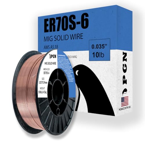
Do Your Best Work ... Color all your clients impressed with the precision and arc control of the ER70S-6 solid MIG welder wire. You'll love the low splatter whether you're performing single or multi-pass welds. Great for T-joints, butt welds & lap welds.

High-quality: ARCCAPTAIN's ER70S-6 mig welding wire .035" meets industry standards(Net Weight: 10lbs), ensuring consistent performance, superior strength. With its smooth feeding and stable welding parameters, you can achieve optimal penetration, high deposition rates, and exceptional overall welding performance.

ER70S-6 MIG WIRE: It's the most common wire of the copper-coated mild steel GMAW (MIG) wires for single or multiple pass welding.
Pros and Cons of Thin and Thick Materials
Thinner Sheet
Advantages: Lower weight, easier forming, faster cutting, and lower material use where the design permits it.
Disadvantages: Greater sensitivity to burn-through, distortion, dents, edge damage, fit-up gaps, and local buckling.
Thicker Sheet or Plate
Advantages: More material to resist wear, impact, and local deformation, with a larger heat sink during welding.
Disadvantages: Greater weight, higher cutting and handling demands, more welding power, possible multi-pass preparation, and higher material and consumable use.
Many fabricated assemblies combine the two: a thicker frame carries the load while a thinner skin closes the structure. The transition must still be designed so heat and stress do not concentrate at the thinner member.
Real-World Welding Examples
Automotive Body Repair
Body-panel thickness varies by vehicle and location, so measure the original panel and replacement patch. Tight fit-up, small MIG wire or controlled TIG, widely spaced tacks, backing bars, and patient heat sequencing help prevent oil-canning and warping.
Mower Deck or Equipment-Skin Repair
Remove damaged and thinned metal until sound material remains. Match the patch to the measured base thickness, control gaps, and choose a process that can operate reliably at the required low or moderate heat. Do not assume one stick-electrode amperage works for every deck.
Trailer and Equipment Fabrication
Use rated plans or engineered drawings for frame members, couplers, suspension mounts, safety-chain points, and tie-downs. Gauge may be useful for nonstructural skins or guards, but the frame requires defined member size, wall thickness, material grade, weld details, and load rating.
Pipeline, Pressure, and Code Work
Code work follows the applicable construction standard, material specification, approved joint design, qualified procedure, qualified welder requirements, inspection plan, and acceptance criteria. A generic online gauge or amperage chart is not a substitute for those documents.
Advanced Tips for Welding Across Different Thicknesses
- Aim more heat toward the thicker member: Let the weld pool wash onto the thin member without dwelling on its edge.
- Taper abrupt transitions: Where the design permits, a gradual transition can reduce stiffness and stress concentration.
- Use chill bars correctly: Copper or aluminum backing can support the puddle and absorb heat. Keep it clean and compatible with the process.
- Use run-on and run-off tabs for starts and stops: They help move arc-start and crater defects outside the finished joint; they are not a replacement for a heat sink.
- Control sequencing: Back-step or skip sequences can balance shrinkage, but the pattern should suit the joint and procedure.
- Treat pulse settings as machine-specific: Pulse frequency, peak current, background current, and duty cycle must be tuned for the alloy, thickness, joint, and machine.
- Track interpass temperature where required: Use the limits in the WPS or filler and base-material guidance rather than applying one universal maximum.
Conclusion
Gauge thickness is useful shop shorthand, but it is not a complete measurement or a structural rating. The reliable workflow is simple: identify the material, measure the actual thickness, use the correct material-specific chart, and select welding parameters from the machine guidance or approved procedure.
On thin sheet, control fit-up, filler size, arc time, and weld sequence to prevent burn-through and distortion. On heavier material, confirm joint access, heat input, fusion, and any procedure requirements. Most importantly, treat coatings, fumes, containers, combustibles, and safety-critical structures as separate hazards that a gauge chart cannot solve.
I still keep a chart near the welding cart, but I reach for the micrometer before trusting it. A helmet magnifying lens—often called a cheater lens—can also improve visibility when working on tiny joints. Measure first, test on matching scrap, and let the finished weld prove that the full setup is right.
Frequently Asked Questions
What gauge thickness should I use for a DIY trailer frame?
There is no safe universal gauge for a trailer frame. Capacity depends on the material grade, tube or channel shape, wall thickness, span, axle and suspension layout, tongue design, joint details, fatigue, corrosion, and intended gross vehicle weight. Use rated plans or an engineered design. Twelve- or 14-gauge sheet may be appropriate for some skins or guards, but that does not establish the frame’s load rating.
How do I convert gauge to inches for aluminum welding?
Use an aluminum-specific chart rather than a carbon-steel table. For example, nominal 16-gauge aluminum is about 0.0508 inch or 1.29 mm. Measure the actual sheet with a micrometer or caliper because coatings, tolerance, damage, and supplier conventions can change the reading.
What is the difference between steel and stainless gauge thickness?
The same gauge number can represent different nominal thicknesses. Common 18-gauge carbon steel is about 0.0478 inch, while 18-gauge stainless is about 0.0500 inch. Stainless also transfers heat differently and can distort easily, so do not automatically increase amperage. Use the correct filler, shielding gas, machine chart, and test coupon for the exact stainless grade.
Can I weld thin-gauge metal without burning through?
Yes. Confirm the actual thickness, maintain tight fit-up, use a low-heat-capable process, select small filler wire where appropriate, and make short separated welds. A clean copper or aluminum backing bar can support the joint and remove heat. Always tune the setup on matching scrap before welding the finished part.
Why does my weld look good but fail on thicker material?
A smooth surface bead can hide lack of fusion. Possible causes include inadequate heat at the joint faces, excessive travel speed, poor torch or electrode angle, long stickout, contamination, insufficient root access, or an unsuitable joint design. Do not simply increase amperage by a fixed percentage. Compare the setup with the machine chart or WPS, prepare a test coupon, and use an appropriate bend, break, macroetch, or specified inspection method.
Sources
- 15 U.S.C. §206 — Standard Gauge for Sheet and Plate Iron and Steel — backs the federal gauge table and its 1893 statutory origin.
- National Bureau of Standards Circular 31: Copper Wire Tables — explains the history of wire gauges, AWG development, and the value of specifying actual dimensions.
- Miller: Successfully Welding Sheet Metal with MIG and TIG — supports thin-sheet wire selection, heat control, skip welding, fit-up, and backing-bar guidance.
- Miller: Setting the Correct MIG Welding Parameters — supports parameter selection and troubleshooting for voltage, wire feed, travel speed, and penetration.
- OSHA 29 CFR 1910.252 — Welding, Cutting, and Brazing — supports combustible control, hot-work precautions, and fire-watch requirements.
- OSHA Hexavalent Chromium Guidance — supports the stainless-welding fume and chromium-exposure warnings.