
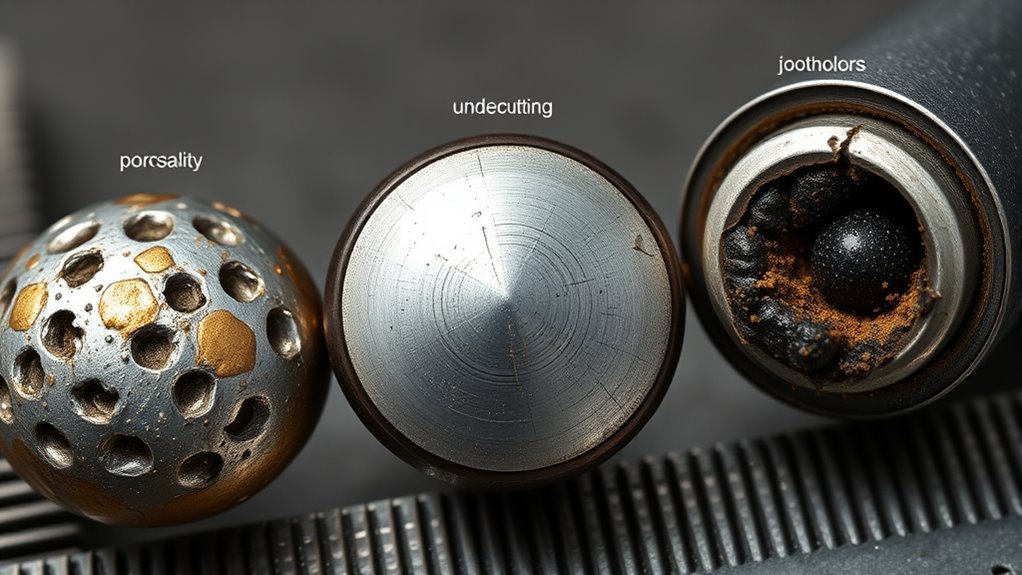
Small weld imperfections can signal poor technique, contamination, incorrect settings, or a joint that needs more testing. You can find many surface problems by cleaning the weld, using strong light, checking it from several angles, and measuring its shape. However, a visual check cannot confirm every internal flaw, so safety-critical welds must be judged against the applicable drawing, procedure, code, or inspection plan.
Quick Answer
Identify visible welding defects by cleaning the joint, lighting it from several angles, and checking the weld face, toes, crater, root, and heat-affected zone. Look for cracks, surface pores, undercut, overlap, underfill, burn-through, poor shape, and misalignment. Use qualified NDT when flaws may be internal.
Key Takeaways
- Visual testing is best for surface conditions, weld dimensions, fit-up, and workmanship that you can directly see.
- A visible indication is not automatically a rejectable defect. Acceptance depends on the applicable drawing, welding procedure, contract, code, or standard.
- Cracks, burn-through, severe undercut, and suspected lack of fusion need prompt review, especially on load-bearing, pressure, vehicle, trailer, lifting, or safety-critical parts.
- Internal porosity, slag inclusions, incomplete penetration, and lack of fusion may require penetrant, magnetic particle, ultrasonic, or radiographic testing.
- Record the location, size, orientation, and appearance of each indication before grinding or repairing it.
At a Glance
| Time Required | A few minutes for a small accessible weld; longer for complex joints, measurements, photographs, or formal documentation |
| Difficulty | Beginner for basic screening; trained or qualified personnel for code acceptance and safety-critical decisions |
| Tools Needed | Work light, wire brush or approved cleaning tool, magnifier, ruler or weld gauge, marker, camera, and the applicable drawing or acceptance criteria |
| Cost | Usually little or no added cost when basic tools are already available; gauges, access equipment, and professional NDT add cost |
Common Visual Indicators of Welding Defects
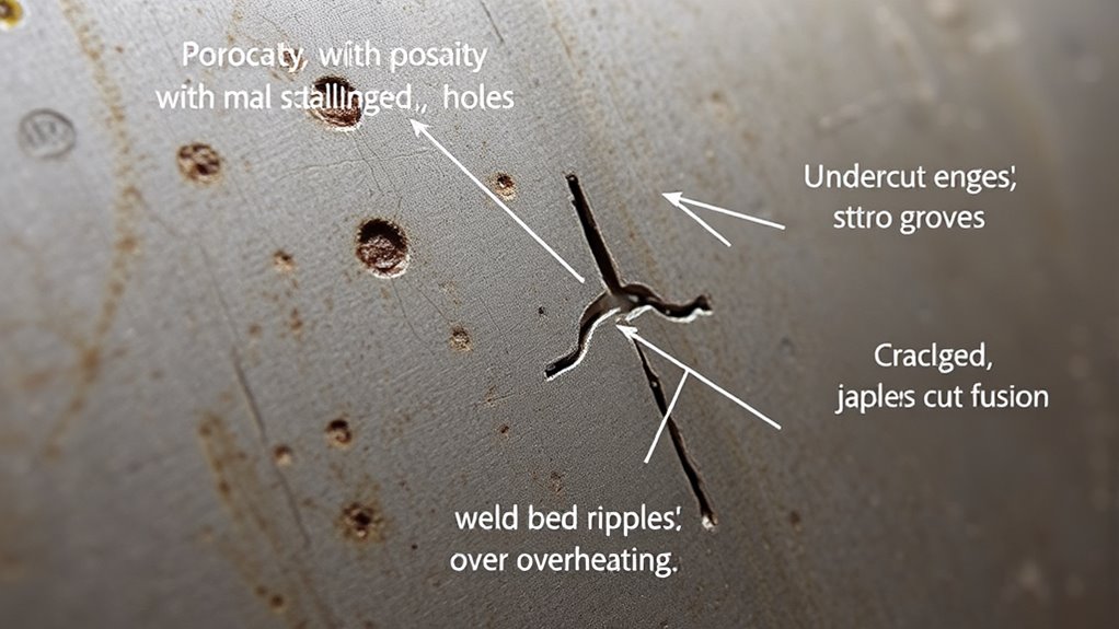
Visual testing lets you evaluate surface discontinuities, weld dimensions, and general workmanship with your eyes or optical aids. It is often the first inspection method, but it needs a clear line of sight, suitable lighting, a clean surface, and an inspector who knows what the joint should look like.
Use the word indication carefully. A groove, pore, crack-like line, or uneven profile is something you observe. It becomes a rejectable defect only when it exceeds the acceptance limits for the job. Those limits may come from a drawing, welding procedure specification, customer requirement, or welding code.
| Visible indication | What it may look like | What to do next |
|---|---|---|
| Crack | A sharp linear opening in the weld, crater, toe, root, or heat-affected zone | Stop and isolate the part when failure could cause injury or damage. Have the crack evaluated before repair or use. |
| Surface porosity | Round pinholes, pits, or clustered openings that break the weld surface | Check cleanliness, moisture, shielding, gas delivery, arc length, and consumable condition. |
| Undercut | A groove melted into the base metal along the weld toe and left unfilled | Measure its length and depth where required, then compare it with the applicable acceptance criteria. |
| Overlap | Weld metal that rolls onto the base metal without a smooth fused transition at the toe | Review travel speed, electrode or gun angle, heat input, and deposited metal volume. |
| Underfill or undersized weld | The weld face or throat is below the required contour or dimension | Measure it with the correct gauge and compare it with the drawing or weld symbol. |
| Burn-through | A hole or missing section of base metal at the root, often with excessive sagging or penetration | Check heat input, travel speed, fit-up, root gap, material thickness, and backing. |
| Surface slag entrapment | Dark or glassy material trapped in a surface-breaking pocket, toe, or interpass groove | Remove slag between passes and review bead placement, joint access, current, and travel speed. |
| Misalignment or distortion | Parts offset from the intended position, angular change, bowing, or warping | Compare the joint with dimensional tolerances and review restraint, sequence, and heat control. |
Some serious imperfections may not produce a clear surface sign. Lack of fusion, incomplete penetration, internal slag, and subsurface porosity can remain hidden even when the weld face looks smooth. A rough-looking transition alone does not prove incomplete fusion.
Warning: Do not return a cracked, burned-through, or questionably fused load-bearing weld to service based only on appearance. Isolate the part and have it reviewed by a qualified person when failure could injure someone or damage equipment.
Understand Various Types of Weld Defects
Weld imperfections fall into two practical groups: conditions you can see at the surface and conditions hidden inside the weld. Learning the difference keeps you from overconfidence during a basic visual check.
Common Defect Types
- Cracks: Linear fractures that may form in the weld metal, crater, fusion boundary, root, or heat-affected zone.
- Porosity: Gas cavities in the solidified weld metal. Only pores that break the surface are directly visible.
- Slag inclusions: Nonmetallic material trapped in or between weld passes. Surface-breaking slag may be visible, but internal slag normally needs another test method.
- Lack of fusion: Weld metal that did not fuse completely with the base metal or a previous pass. It may be surface-breaking or fully internal.
- Incomplete penetration: The weld does not extend through the intended root area. You can only judge it visually when the root is accessible and the joint design allows you to see it.
- Undercut, underfill, overlap, excess reinforcement, and incorrect weld size: Shape or dimensional imperfections that you can often evaluate visually and with gauges.
- Burn-through: Excessive melting that creates a hole or loss of metal at the root.
- Misalignment and distortion: Dimensional conditions that may affect fit, loading, or service performance.
The article uses the familiar phrase “weld defects,” but many standards prefer imperfection or discontinuity until the indication is compared with an acceptance limit. Weld acceptance criteria vary by application and code, so appearance alone cannot provide a universal pass or fail decision.
Causes of Defects
Most visible problems trace back to one or more parts of the welding setup or technique:
- Contamination: Oil, paint, rust, scale, moisture, coatings, or dirty filler can contribute to porosity and poor fusion.
- Shielding problems: Leaks, drafts, blocked nozzles, incorrect gas, unstable flow, or excessive stickout can expose the weld pool to air in gas-shielded processes. This MIG welding problems and solutions guide covers related setup checks.
- Incorrect parameters: Heat input, voltage, current, wire feed speed, travel speed, and arc length must suit the process, joint, consumable, material, and position.
- Poor joint preparation or access: A narrow groove, inconsistent root opening, poor fit-up, or restricted torch access can contribute to lack of fusion or incomplete penetration.
- Technique errors: Incorrect work angle, travel angle, manipulation, bead placement, or failure to pause at the toes can create overlap, undercut, slag pockets, or uneven fusion.
- Heat and restraint: High restraint, unsuitable filler, rapid cooling, hydrogen, or poor sequence can raise cracking risk. Excessive heat can cause burn-through and distortion.
- Poor interpass cleaning: Slag left between passes can become trapped in the completed weld. Proper preparation and technique are also covered in these flux-core welding tips for beginners.
Visual Inspection Techniques
Inspect the joint before welding, during welding when the procedure allows, and after the weld is complete. Before welding, check joint preparation, cleanliness, alignment, root opening, backing, tack welds, and access. During welding, watch bead placement, interpass cleaning, crater filling, arc strikes, and visible distortion. After welding, inspect the complete weld face, toes, starts, stops, crater, accessible root, and heat-affected zone.
Use light from more than one direction because a single shadow can hide a fine groove or crack-like line. View the weld from several angles, use a mirror or borescope for restricted areas, and measure dimensions instead of judging them by eye.
Before You Inspect a Weld
Start with a safe, stable work area. Confirm that welding has stopped, energy sources are controlled as required, hot metal is identified, and the part is supported so it cannot shift. Welding areas can expose you to burns, sharp edges, fumes, radiation, electrical hazards, and falling or moving parts. Follow suitable work practices and PPE guidance, including OSHA’s welding hazard information.
Gather the information that defines an acceptable weld:
- The drawing and weld symbol
- The welding procedure specification, when one applies
- The required weld size, length, contour, and location
- Material and joint type
- Applicable code, standard, contract, or customer acceptance criteria
- Any hold points or required NDT method
Then prepare the surface without hiding evidence. Remove loose slag, dirt, soot, and spatter that blocks your view, but do not grind away an indication before you record it. Use cleaning tools that will not contaminate the material. For example, stainless steel should not be brushed with a carbon-steel brush that has been used on mild steel.
Basic inspection tools include:
- A bright work light or flashlight
- A clean wire brush, chipping tool, or approved surface-cleaning tool
- A magnifying glass, inspection mirror, or borescope
- A ruler, fillet weld gauge, bridge cam gauge, or caliper suited to the measurement
- A straightedge or square for alignment and distortion checks
- A marker, notebook, inspection form, and camera
- Eye protection, gloves, and other PPE required for the area
If the inspection area includes cutting, grinding, hot slag, or nearby hot work, use a suitable PPE and work-area setup checklist rather than relying on ordinary shop clothing.
Learn Inspection Techniques for Effective Defect Detection
Use a repeatable sequence so you do not focus on the weld face and miss the toes, crater, root, or surrounding base metal.
- Confirm the inspection criteria: Read the drawing, weld symbol, procedure, and acceptance requirements before deciding whether anything passes or fails.
- Identify the joint and weld: Record the part, joint number, weld location, process, material, and inspection stage.
- Check surface condition and access: Make sure the area is clean enough to see and that you can view all required surfaces safely.
- Scan the full joint: Inspect the weld face, both toes, starts, stops, crater, accessible root, tack locations, and heat-affected zone.
- Change the light and viewing angle: Move the light and your line of sight to reveal fine cracks, undercut, pits, overlap, or contour changes.
- Measure the weld: Check size, length, reinforcement, undercut, alignment, and other specified dimensions with the correct gauge.
- Mark and document indications: Note each indication’s exact location, length, direction, appearance, and measured size. Add a scale to photographs when possible.
- Compare with acceptance criteria: Decide whether the indication is acceptable, needs additional NDT, or requires repair. Do not invent a limit when the controlling document is unavailable.
Pro Tip: Take one overall photo to show the weld’s location, then a close photo with a ruler or gauge beside the indication. Photograph the same area again after an approved repair so the record shows what changed.
Products Worth Considering

【7 pieces Weld Fillet Gauges】: 7 pieces weld fillet gauges are held by bolt and nut that can be disassembled, each weld gauge can be used to check the size of fillet legs and fillet throats
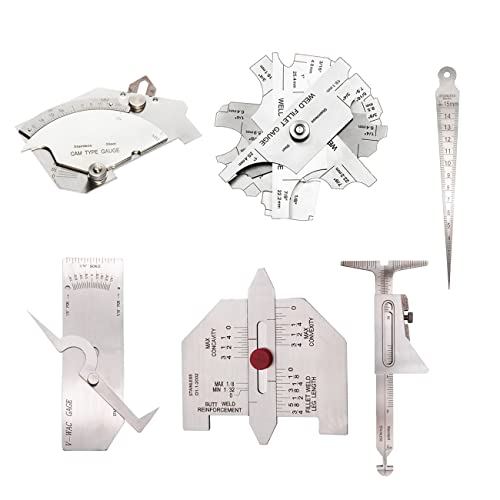
❤6 PCS WELD GAUGE SET❤ Package Includes 1 x Cam Type Gauge, 1 x Weld Fillet Gauge, 1 x Hi-Lo Welding Gauge, 1 x Taper Welding Gauge, 1 x Undercuts Checking Gauge, 1 x Convexity Concavity Checking Gauge, 6 x Instructions, 6 x Pouches. These Weld Gauges Are Suitable for Measuring Length, Height, Width and Angle for Welding. Made of Stainless Steel.

❤WELD GAUGE SET❤ Package Includes 1 x Undercuts Checking Gauge, 1 x Convexity Concavity Checking Gauge, 2 x Instructions, 2 x Pouches. These Gauges with Imperial Measurement Is Suitable for Welding Inspection.
What to Record in an Inspection Log
- Part, drawing, joint, and weld identification
- Date, inspector, and inspection stage
- Welding process and material, when known
- Applicable acceptance criteria
- Surface condition and areas that were not accessible
- Indication type, location, orientation, length, depth, or other measured dimension
- Photographs and gauge readings
- Disposition: accepted, rejected, requires NDT, or sent for engineering review
- Repair method, reinspection result, and final status
How to Spot Cracks and Burn-Through in Welds
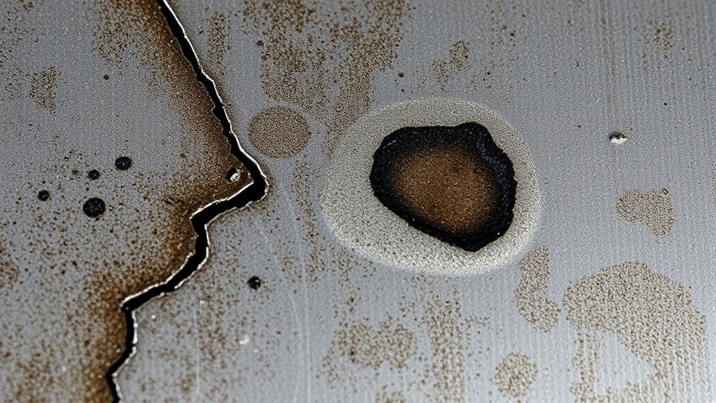
Cracks and burn-through are different indications, but both deserve immediate attention. Inspect them under strong light after the surface is clean enough to see the metal.
- Check the crater and weld ends: Crater cracks may form where the arc stopped without filling the crater. Look for fine lines radiating from or crossing the depression.
- Check along and across the bead: Longitudinal cracks run generally with the weld. Transverse cracks cross it. Toe cracks follow or branch from the fusion boundary.
- Check the heat-affected zone: Look for sharp linear indications beside the weld, especially near abrupt profile changes, attachments, arc strikes, or highly restrained areas.
- Check the accessible root: Burn-through appears as an opening or missing metal. Excessive root penetration may appear as a large sag or protrusion, but acceptance depends on the joint requirements.
- Check fit-up and distortion: A wide root gap, poor backing, excessive heat input, or slow travel can contribute to burn-through, while restraint and unsuitable welding conditions can contribute to cracking.
Do not classify discoloration, soot, or a dark spot as burn-through unless there is actual melting, an opening, or a dimensional condition you can confirm. Likewise, a scratch can resemble a crack. When a linear indication is uncertain, qualified liquid penetrant or magnetic particle testing may be appropriate.
On flux-cored welds, surface grooves called worm tracks can point to gas escaping through the slag system. Record their length and distribution, then compare them with the procedure and acceptance requirements.
Identifying Porosity and Slag Inclusions
Surface porosity appears as round pits, pinholes, or clustered cavities that open to the weld surface. It may be scattered, grouped, or aligned. Internal porosity cannot be confirmed by looking at the weld face, even when the surface looks clean.
Common contributors include dirty metal, moisture, contaminated consumables, inadequate or disturbed shielding, leaks, drafts, excessive arc length, and poor gas coverage. This guide to porosity in arc welding covers related troubleshooting steps.
Slag inclusions form when nonmetallic slag becomes trapped in the weld. A surface-breaking inclusion may look like a dark or glassy pocket or line after loose slag is removed. However, most internal slag cannot be confirmed visually. According to TWI’s guidance on slag inclusions, prevention depends on bead shape, correct technique and parameters, joint access, and complete slag removal between passes.
When porosity or slag may extend below the surface, the inspection method should match the suspected flaw and material. TWI notes that surface-breaking porosity may be examined with penetrant or magnetic particle methods, while subsurface porosity is evaluated with radiography or ultrasonic testing, with radiography often more effective for characterizing porosity.
Note: Do not probe a pore or slag pocket with a sharp tool and then treat the changed opening as the original indication. Photograph and measure it first, then follow the approved examination or repair procedure.
Top Techniques to Prevent Common Welding Defects
Prevention starts before the arc. Use the approved procedure and verify the details that control fusion, shielding, bead shape, and heat input.
- Prepare the joint: Remove contaminants, confirm bevels and root openings, and make sure the joint provides access for the selected process.
- Use compatible materials and consumables: Match the filler, shielding gas, polarity, wire or electrode, and storage requirements to the procedure and base metal.
- Set and verify parameters: Use the procedure or machine data for current, voltage, wire feed speed, travel speed, gas, and other variables. Make a test weld when appropriate.
- Control arc length and angles: Keep a stable arc and use the work and travel angles required for the process, position, and joint.
- Watch the toes and root: Place the arc where fusion is needed. Avoid letting a large weld pool run ahead of the arc and hide unfused metal.
- Clean between passes: Remove slag and contaminants before depositing the next pass, especially in grooves, undercut, and tight joint areas.
- Fill starts and stops: Feather or prepare stop areas as required and fill the final crater to reduce crater cracking and trapped slag.
- Control heat and sequence: Use tack welds, clamps, balanced sequences, skip welding, or back-step methods when the procedure permits them.
- Verify weld size: Follow the drawing and weld symbol. More weld metal is not automatically better. Review the required geometry and this explanation of maximum fillet weld size.
- Inspect early: Catch poor fit-up, a contaminated pass, undercut, or an unfilled crater before later passes hide the problem.
Products Worth Considering

Value Pack: The package includes 24 packs of butt welding clamps, enough quantity to meet your daily needs and replacements. Each butt welding clamps is individually wrapped in a small bag, convenient to carry and use.

Exclusive Patent Pending Design, Which Easily Provides A Perfectly Beveled 45° Weld-Prepped Edge In 20 Or 18 Gauge Sheet Metal

Defect, Cause, and Correction Guide
| Indication | Likely contributors | Process checks |
|---|---|---|
| Surface porosity | Contamination, moisture, shielding loss, leaks, drafts, excessive stickout | Clean and dry materials, inspect gas delivery, protect shielding, verify consumables and technique |
| Undercut | Excessive travel speed or arc length, poor angle, excessive heat, no pause at the toe | Correct parameters and angles, control weave width, pause where the procedure permits |
| Overlap | Low effective heat, slow travel, wrong angle, excessive deposit | Direct the arc at the fusion boundary, balance heat and travel, reduce excess metal |
| Lack of fusion | Restricted access, poor cleaning, incorrect parameters, excessive speed, wrong manipulation | Improve preparation and access, clean thoroughly, use approved parameters, place the arc at the sidewall or previous pass |
| Slag inclusion | Slag left between passes, pockets caused by bead shape or undercut, poor access | Remove slag completely, improve bead placement, correct current and travel speed, grind tight pockets when approved |
| Burn-through | Excessive heat, slow travel, large root gap, thin material, poor backing | Reduce heat input within the procedure, improve fit-up, adjust travel, use approved backing or sequence |
| Crater crack | Unfilled crater, abrupt arc stop, shrinkage and restraint | Use crater-fill or downslope controls, back-step where appropriate, fill the crater before breaking the arc |
When Visual Inspection Is Not Enough
Visual inspection can find surface conditions and dimensional problems, but it cannot confirm the internal soundness of a weld. Use additional NDT when the drawing, code, inspection plan, service risk, or a suspicious indication requires it.
| Method | Best suited to | Important limitation |
|---|---|---|
| Liquid penetrant testing (PT) | Surface-breaking discontinuities in clean, solid, nonporous materials | Does not find flaws that do not reach the surface; surface preparation and procedure control matter |
| Magnetic particle testing (MT) | Surface and near-surface discontinuities in ferromagnetic materials | Not suitable for nonferromagnetic materials such as aluminum or austenitic stainless steel |
| Ultrasonic testing (UT) | Surface and subsurface discontinuities, including many planar flaws | Requires qualified technique, calibration, access, and interpretation; geometry can complicate results |
| Radiographic testing (RT) | Internal volumetric conditions such as porosity and some inclusions | Uses ionizing radiation, requires controlled access and qualified personnel, and may be less sensitive to some planar flaw orientations |
The American Society for Nondestructive Testing’s method overview explains that each NDT method has different material, access, depth, and flaw-orientation limits. The correct method comes from the inspection plan or a qualified examiner, not from guessing based on the weld’s appearance.
Use professional inspection for welds on pressure-retaining equipment, lifting devices, structural members, trailers, vehicle suspension or steering parts, fall-protection anchors, fuel systems, and other joints where failure could cause serious harm. The exact requirement depends on the governing code and application.
Note: A smooth, attractive bead can still contain internal lack of fusion, incomplete penetration, slag, or porosity. Appearance is evidence, not proof of internal quality.
How to Decide Whether a Weld Is Acceptable
Do not use a universal “good weld” picture as the final acceptance standard. A weld may be acceptable for one application and unacceptable for another because required size, loading, material, service temperature, fatigue exposure, and consequences of failure differ.
- Find the controlling requirement: Use the drawing, weld symbol, procedure, contract, repair manual, code, or engineer’s instruction.
- Identify the indication: Describe what you can actually see or measure without claiming an internal flaw that has not been tested.
- Measure it correctly: Use the specified gauge and record the length, depth, spacing, or dimension required by the acceptance criteria.
- Check the limit: Compare the measured indication with the applicable acceptance table or written requirement.
- Escalate uncertainty: Request additional NDT or engineering review when the flaw may be hidden, the requirement is unclear, or failure risk is high.
- Document the disposition: Record whether the weld is accepted, rejected, repaired, or awaiting further evaluation.
A visible irregularity is an indication. The applicable acceptance criteria determine whether that indication is a rejectable defect.
Repairing a Defective Weld
Many weld imperfections can be repaired, but the repair must address both the damaged metal and the cause. Mark and document the area first. Then follow the approved repair procedure, remove the unacceptable weld metal without damaging sound base metal, prepare and clean the joint, reweld with qualified settings and technique, and reinspect the repaired area with the required method.
Do not casually grind and cover a crack. Cracks may extend beyond the visible end, and some repairs require crack removal verification, preheat, controlled consumables, engineering approval, or NDT before and after welding.
Frequently Asked Questions
How do you identify welding defects?
Clean the weld, inspect the face, toes, crater, accessible root, and heat-affected zone under strong light, then measure any irregularity. Look for cracks, surface pores, undercut, overlap, underfill, burn-through, poor contour, and misalignment. Use the applicable acceptance criteria and additional NDT when a flaw may be internal.
How do you inspect a weld visually?
Confirm the drawing or procedure, clean the surface, use light from several angles, inspect every accessible part of the joint, measure the weld with suitable gauges, photograph and record indications, and compare the results with the governing acceptance limits.
What are 10 common welding imperfections?
Common imperfections include cracks, porosity, slag inclusions, lack of fusion, incomplete penetration, undercut, underfill, overlap, burn-through, and misalignment or distortion. Not every imperfection is automatically rejectable. The application’s acceptance criteria determine whether it is a defect.
What are the visual signs of an inadequate weld?
Possible signs include cracks, clustered surface pores, undercut, overlap, burn-through, an unfilled crater, inconsistent bead width, incorrect weld size, arc strikes, visible surface slag, and misalignment. A smooth bead can still contain internal flaws, so appearance alone does not confirm adequacy.
What is the difference between a weld discontinuity and a defect?
A discontinuity or imperfection is an interruption or irregularity in the weld or base metal. It becomes a defect when it exceeds the acceptance criteria for the specific job. The same type or size of indication may be acceptable in one application and rejectable in another.
Can visual inspection confirm weld penetration or fusion?
Only in limited cases. You may inspect penetration at an accessible root, and surface-breaking lack of fusion may produce a visible indication. Internal incomplete penetration or lack of fusion can remain hidden and may require ultrasonic, radiographic, penetrant, or magnetic particle testing as specified.
Can you repair a weld after finding defects?
Many weld defects can be repaired after the cause is identified and the unacceptable metal is removed with an approved method. Prepare and clean the joint, reweld under the required procedure, and reinspect it. Safety-critical repairs may require engineering approval, qualified welders, and specified NDT.
Conclusion
A careful visual inspection helps you find surface cracks, porosity, undercut, overlap, burn-through, poor contour, incorrect size, and alignment problems before a welded part goes into service. The best inspection is systematic: know the requirement, clean the area, light it from several directions, inspect every accessible surface, measure what you find, and keep a clear record.
Visual inspection also has a firm limit. It cannot prove that the inside of a weld is sound. When a joint carries serious load, pressure, vibration, or safety risk, follow the applicable code or repair procedure and use qualified NDT or professional inspection when required.
Sources
- American Society for Nondestructive Testing: Visual Testing — surface inspection capabilities, tools, and limitations
- American Society for Nondestructive Testing: NDT Methods — penetrant, magnetic particle, ultrasonic, and radiographic testing uses
- TWI: Application Standards, Codes of Practice and Quality Levels — code-specific weld acceptance criteria
- TWI: Slag Inclusions — causes, prevention, cleaning, and inspection considerations
- TWI: Lack of Sidewall and Inter-Run Fusion — causes, detection limits, and remedial action
- Occupational Safety and Health Administration: Welding Hazards and Solutions — welding-area hazards and protective practices




