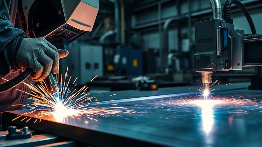
You’re choosing between plasma and laser cutting, but “better” depends on tolerance, thickness, and budget. Laser cutting delivers tight kerfs, smooth edges, and sub-0.1 mm accuracy on thin to medium stock, including non-metals. Plasma wins on thick, conductive metals with faster throughput and lower cost per cut, but leaves wider kerfs and heat-affected edges. Consider cut speed, feature size, material mix, and post-processing time—because the ideal process hinges on specific constraints you can quantify next.
How Laser Cutting Works
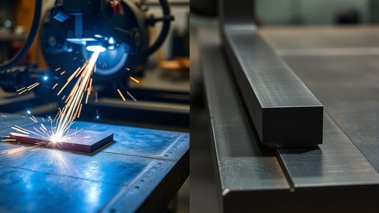
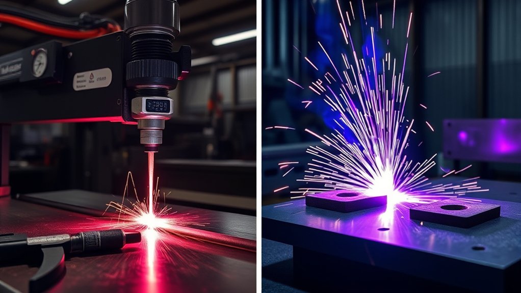
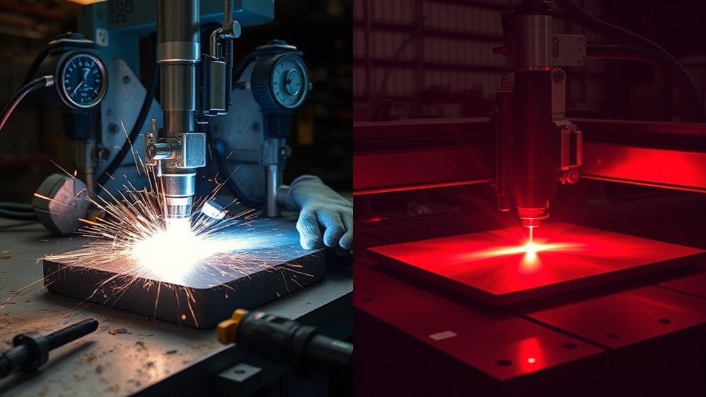
Although the physics are complex, laser cutting is straightforward in practice: a CNC-controlled nozzle directs a high-intensity, coherent light beam onto the workpiece, rapidly heating, melting, and vaporizing the material along a programmed path.
You load a CAD file, post-process toolpaths, and the machine executes them with closed-loop motion control. Using mature laser technology, the system maintains beam quality (mode, focus, and power density) to deliver narrow kerfs and tight tolerances—often reaching ±0.003 mm on stable setups.
You select parameters by material and thickness: wavelength, focal position, assist gas type/pressure, feed rate, and power. Thin gauges run fastest, yielding smooth, burr-free edges that minimize secondary finishing.
This method supports metals, plastics, wood, and ceramics, expanding cutting applications across prototyping and production. Since its 1960s industrial debut, iterative advances—higher wall-plug efficiency, better beam delivery, smarter CNC algorithms—have increased throughput and consistency.
The result is repeatable precision on intricate geometries with minimal heat-affected zones and efficient material utilization.
How Plasma Cutting Works
While it relies on an electric arc rather than a focused photon beam, plasma cutting is a controlled thermal-separation process: a power supply generates a DC arc between a nonconsumable electrode and the workpiece, ionizing a process gas (often air, nitrogen, or oxygen) into plasma that can exceed 20,000°C.
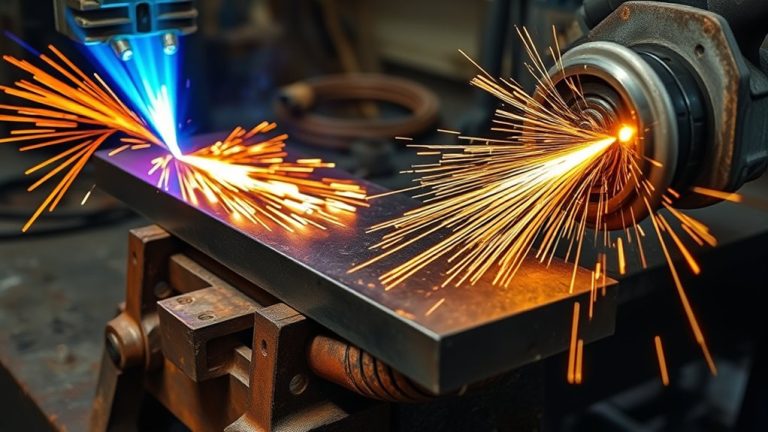
You accelerate this plasma through a constricted nozzle to form a high-velocity jet that transfers heat and momentum to the metal. The jet melts a narrow kerf while the gas stream ejects molten material, completing separation.
You’ll exploit plasma properties—extreme temperature, electrical conductivity, and jet velocity—to cut steels, stainless steel, aluminum, brass, and copper.
Typical cutting applications span fabrication, repair, and construction where conductive metals dominate. With adequate amperage and gas selection, you can process material up to about 1.5 inches (≈38 mm).
Choose handheld torches for mobile work and fit CNC tables for repeatability and throughput. Calibrate current, standoff, travel speed, and gas flow to stabilize the arc and control edge quality.
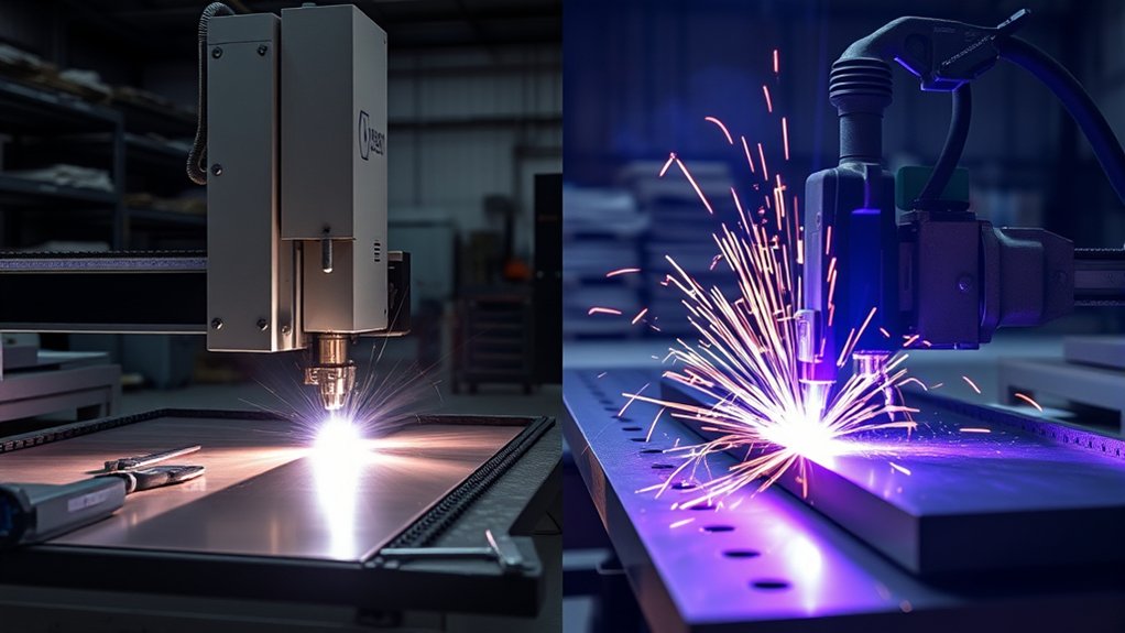
Key Differences: Precision, Speed, and Material Capability
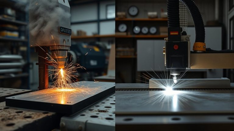
You’ll compare tolerances and kerf first: lasers routinely hold ±0.003 mm with narrow kerf, while plasma averages ~±0.1 mm with a wider cut path.
Next, quantify cut speed by thickness: lasers lead on thin sheet with higher IPM and lower energy per cut, but plasma typically wins on thicker stock, sustaining fast cuts up to ~1.5 in where many lasers cap near ~0.75 in.
Finally, map material compatibility: lasers process metals plus non-conductives like plastics and wood, whereas plasma is limited to electrically conductive metals.
Tolerances and Kerf
Two core metrics—tolerance and kerf—separate laser and plasma cutting in precision, speed, and material capability. In a tolerance comparison, you’ll hold ±0.002 inches with laser, versus roughly ±0.1 inches with plasma. That delta drives fit-up quality, interchangeability, and rework risk. Kerf width is similarly decisive: laser’s narrower kerf yields tighter nesting, less scrap, and cleaner geometry retention, while plasma’s wider kerf sacrifices fine detail.
| Metric | Typical Outcome |
|---|---|
| Tolerance | Laser: ±0.002 in; Plasma: ±0.1 in |
| Kerf Width | Laser: narrow, minimal waste; Plasma: wider |
| Edge Quality | Laser: smooth, burr-free; Plasma: rougher, slag possible |
Process selection follows material and feature demands: choose laser for thin stock up to ~19 mm and intricate profiles; choose plasma for thicker conductive metals where ultra-tight tolerances aren’t critical.
Cut Speed by Thickness
Three variables—thickness, material type, and required precision—govern cut speed differences between plasma and laser. For conductive metals at higher material thickness, plasma delivers superior cutting efficiency.
As a benchmark, you’ll see about 10 inches per minute on 1-inch steel with plasma versus roughly 6 ipm with laser. Plasma also scales to extreme thicknesses, reaching up to 150 mm, where lasers slow dramatically or become impractical.
For thin sections, especially under 30 mm, laser cutting typically runs faster and maintains consistency. Fiber lasers excel on sheet gauges, where higher traverse speeds, narrow kerf, and minimal heat input preserve geometry.
If you must hold very tight tolerances (±0.003 mm), prioritize laser and adjust feed rates accordingly; if productivity on thick plate dominates, prioritize plasma and optimize amperage, gas, and nozzle selection.
Material Compatibility Range
Start by matching the process to the material class.
If you need broad material versatility, choose laser cutting; it handles metals plus non-conductives like wood, plastics, and ceramics.
Plasma’s conductive limitations restrict you to steel, aluminum, brass, and other electrically conductive alloys.
For precision-critical parts, lasers deliver ±0.003 mm tolerances and clean, burr-free edges, while plasma typically holds ±0.1 mm and may require finishing.
Align thickness with speed: plasma moves fastest on plate up to ~1.5 inches; lasers excel on thin stock under 25 mm.
1) Metals only: Use plasma when you prioritize throughput on thick conductive plate and accept post-processing.
2) Mixed materials: Use laser for metals and non-metals, high accuracy, and minimal cleanup.
3) Cost posture: Plasma lowers upfront cost; lasers can reduce long-term expenses.
Pros and Cons of Laser Cutting
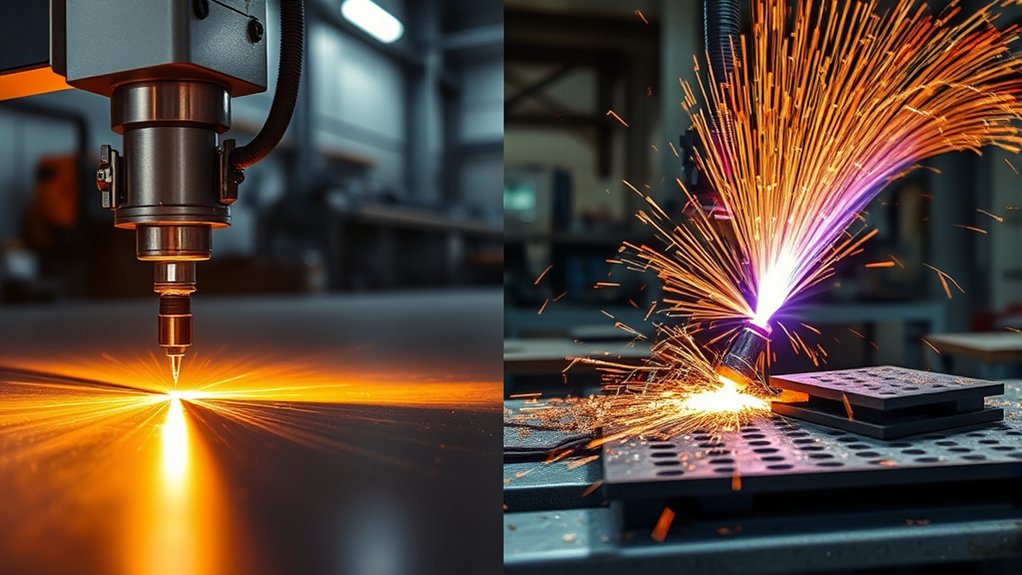
Although both technologies can produce clean cuts, laser cutting distinguishes itself with ±0.003 mm tolerances, smooth burr-free edges, and versatile compatibility across metals, plastics, wood, and ceramics—attributes that reduce post-processing and enable intricate geometries.
You gain application versatility and cost efficiency by nesting dense part layouts, accelerating cycle times on thin stock, and minimizing secondary finishing. For sheet thicknesses under 6–8 mm, you’ll typically see faster feed rates and lower energy per part, improving throughput and unit economics.
Process advantages include tight kerf control, minimal heat-affected zones, and repeatable accuracy across multi-part runs. You can standardize fixtures, leverage CAM automation, and hit tight GD&T callouts with less rework.
However, performance drops on highly reflective alloys such as copper or brass without specialized sources or coatings, and cut quality degrades as thickness approaches ~19 mm. Expect slower speeds, higher power demand, and potential dross beyond that threshold.
Select assist gases, focal length, and pulse parameters deliberately to balance edge quality, speed, and cost.
Pros and Cons of Plasma Cutting
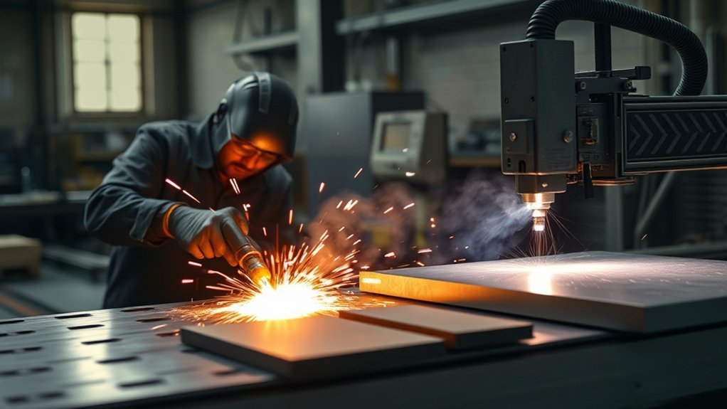
When throughput on thick stock is your priority, plasma cutting delivers: you can slice conductive metals at temperatures near 20,000°C, maintain productive speeds beyond 25–50 mm thickness, and do it with a lower capital outlay than comparable laser systems.
You’ll see clear strengths in heavy fabrication. Plasma achieves rapid pierce and traverse on steel, aluminum, brass, and copper, offering cost efficiency for shops scaling capacity without premium equipment.
Consumables and power draw affect operating expense, but per-part cost typically stays favorable on thick plate.
However, trade-offs matter. A wider kerf and heat-affected zone increase dimensional deviation, often requiring secondary grinding or machining. It’s also limited to conductive materials, so you can’t process wood or plastics.
1) Capability: Reliable cutting at 25–50+ mm; robust for industrial duty cycles.
2) Quality: Larger kerf, more dross; anticipate post-processing to meet tight tolerances.
3) Operational safety: Manage arc glare, fumes, and molten sparks with proper shielding, ventilation, and PPE.
Choosing the Right Method for Your Project
You’ve seen where plasma excels on thick, conductive plate; now align method to specs, material, and budget.
Begin by defining project requirements: material type, thickness, geometry, and edge quality. If you’re cutting steel or aluminum above 0.75 inches and up to 1.5 inches, plasma delivers throughput with typical ±0.1 mm tolerance, accepting post-process deburring.
For thin-gauge parts, micro-features, or assemblies needing press-fit accuracy, laser’s ±0.003 mm precision and burr-free edges reduce secondary operations.
Evaluate budget considerations next. Capital outlay for plasma systems typically ranges $5,000–$20,000; laser systems often run $50,000–$500,000.
Factor operating costs and takt time: plasma minimizes acquisition cost for heavy plate; laser offsets higher purchase price with rework savings and multi-material capability, including plastics and wood.
Make the selection by scoring thickness, tolerance, edge finish, and material versatility against cost and schedule.
Choose plasma for fast, economical thick-metal cuts; choose laser for tight tolerances, intricate designs, and clean edges on thin or non-metal materials.
Frequently Asked Questions
What Are Typical Maintenance Schedules for Plasma vs. Laser Cutters?
You’ll service plasma cutters weekly for consumables, quarterly for torches, annually for power supplies; maintenance frequency is high but maintenance costs are moderate. You’ll service laser cutters daily for optics cleaning, monthly alignments, semiannual filters; lower frequency, higher costs.
How Do Noise Levels Compare Between Plasma and Laser Cutting?
You’ll hear plasma cutting roar—think thunder—producing higher noise pollution, often 90–110 dB. Laser cutting hums—like steady rain—typically 70–85 dB. For a controlled operational environment, you’ll specify enclosures, acoustic barriers, PPE, and verify dB levels via calibrated dosimeters.
What Safety Certifications or Training Are Recommended for Operators?
You should hold OSHA 10/30, NFPA 51B hot work awareness, and first aid/CPR. Complete operator training on lockout/tagout, hazard communication, PPE, fume extraction, and fire watch. Add manufacturer certifications, ANSI Z49.1 welding safety, and annual refresher assessments.
How Do Consumable Lifespans Impact Total Cost of Ownership?
They directly govern total cost of ownership. You quantify consumable costs through lifespan analysis: track arc-on hours, pierce counts, duty cycles, and cut parameters, then model replacement intervals, downtime, inventory carrying costs, and yield impacts to optimize process economics.
Can Either Method Integrate With Automation and Nesting Software?
Yes—think Prometheus bringing fire. You can implement automation integration and nesting software compatibility on both. You’ll deploy CNC controllers, MES links, barcode workflows, and post-processors; validate tool libraries, kerf compensation, lead-ins, and remnant tracking; benchmark throughput, uptime, and yield.
Conclusion
You won’t find a one-size-fits-all winner. Treat the choice like selecting the right blade: laser for tight tolerances, fine kerfs, and mixed materials; plasma for faster throughput and thicker conductive metals at lower cost. Quantify requirements—tolerance (±0.1–0.25 mm vs. ±0.5–1.0 mm), kerf width, heat-affected zone, pierce count, duty cycle, and per-part cost. Then map constraints—budget, edge finish, geometry complexity, and thickness. With those inputs, you’ll choose the most efficient, repeatable, and cost-optimized path.