
Choosing between spray arc MIG welding and short-circuit MIG welding comes down to more than metal thickness. Weld position, wire diameter, shielding gas, machine output, joint design, fit-up, and the required welding procedure all matter. Short-circuit transfer gives better control at lower heat, while spray transfer provides a smoother open arc, higher deposition, and strong fusion potential when the setup is correct.
Quick Answer
Use short-circuit MIG for thin sheet, tack welds, repairs, gaps that need careful control, and most vertical or overhead work. Use spray arc MIG for clean, thicker material in flat or horizontal positions when you have enough machine output and the correct argon-rich shielding gas.
Key Takeaways
- Short-circuit MIG welding offers a small, fast-freezing puddle that works well on thin steel and in all welding positions.
- Spray arc MIG welding offers higher deposition, a smooth arc, little spatter, and good fusion potential on suitable flat or horizontal welds.
- Carbon-steel spray transfer normally needs an argon-rich gas containing at least about 80% argon; 90/10 argon/CO₂ is a common choice.
- There is no universal thickness, voltage, or wire-speed setting that changes every welder from short circuit to spray.
- Conventional short-circuit transfer can lack fusion on thick joints, while standard spray can burn through thin material or sag out of position.
- For structural, pressure, lifting, vehicle-frame, or other safety-critical work, follow the governing code and an approved welding procedure specification.
At a Glance
| Best For | Short circuit for thin metal, repair work, roots under an approved procedure, and positional welding; spray for productive flat or horizontal welds on material that can absorb more heat. |
| Weld Positions | Short circuit can be used flat, horizontal, vertical, and overhead. Standard spray is generally limited to flat grooves and horizontal fillets. |
| Gas and Equipment | Short circuit commonly runs on 75/25 argon/CO₂ for mild steel. Carbon-steel spray needs an argon-rich blend plus adequate voltage, amperage, and duty cycle. |
| Main Risk | Short circuit can produce incomplete fusion on thick joints. Spray can cause burn-through, excessive heat, undercut, or puddle sag when used on unsuitable material or positions. |
Spray Arc vs Short-Circuit MIG Welding Comparison
The biggest difference is how molten wire moves from the electrode into the weld pool. In short-circuit transfer, the wire touches the puddle many times per second. Each contact briefly shorts the circuit, the wire pinches off, the arc re-ignites, and the cycle repeats.
In spray transfer, fine droplets cross an open arc without the repeated wire-to-puddle contact. The process runs above the transition current for the selected wire and gas. It produces a hotter, more fluid puddle and normally offers higher deposition and less spatter than conventional short circuit.
| Factor | Short-Circuit MIG | Spray Arc MIG |
|---|---|---|
| Typical use | Thin sheet, light fabrication, tacks, repair work, controlled roots, and joints that need lower heat input. | Longer welds on clean plate where higher deposition, smooth wetting, and good fusion are useful. |
| Positions | Flat, horizontal, vertical, and overhead when the filler metal and procedure permit. | Normally flat grooves and horizontal fillets. Use pulsed spray or another suitable process for positional work. |
| Heat and puddle | Lower average heat with a smaller puddle that freezes quickly. | Higher current and a larger, more fluid puddle that needs good fit-up and position control. |
| Spatter | More spatter than spray, especially when voltage, inductance, extension, or wire speed is poorly matched. | Usually very little spatter once the process is above transition current with the correct gas. |
| Carbon-steel gas | 75/25 argon/CO₂ is common, although other qualified mixtures may be used. | An argon-rich mixture is required. At least about 80% argon is typical, with 90/10 argon/CO₂ commonly used. |
| Main defect risk | Cold lap, incomplete fusion, or poor penetration when the joint is too thick or the arc is allowed to ride on the puddle. | Burn-through, undercut, excessive heat input, poor root control, or puddle sag. |
Warning: MIG welding exposes you to arc radiation, electric shock, hot metal, fire, compressed gas, and hazardous fumes. Wear a suitable helmet, safety glasses, gloves, flame-resistant clothing, and hearing protection. Secure gas cylinders upright, remove combustibles, provide suitable ventilation or fume extraction, and never weld a tank, drum, closed container, or confined space without an approved procedure. Follow OSHA welding hazard guidance and your equipment manual.
What Is Spray Arc MIG Welding?
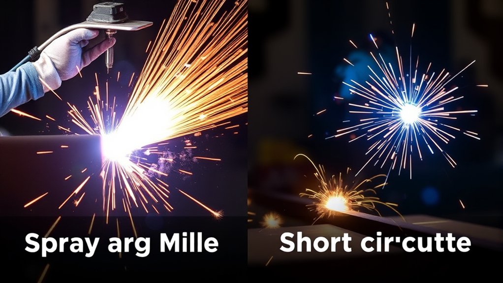
Spray arc MIG welding, also called axial spray transfer, is a GMAW transfer mode in which small molten droplets move across an open arc in a steady stream. The electrode does not repeatedly touch the puddle as it does in conventional short-circuit transfer.
When the wire, gas, current, voltage, and contact-tip-to-work distance are correctly matched, spray transfer produces a stable hum or hiss, a fluid puddle, a smooth bead, and very little spatter. Its higher deposition rate makes it useful for long welds and production work.
Spray transfer requires the welding current to rise above the transition current for the selected setup. Transition current is not one fixed number. It changes with electrode material, wire diameter, shielding-gas composition, electrode extension, and other electrical variables. A setting that produces spray with one wire and gas may remain globular with another.
For that reason, a generic voltage number is not reliable. Start with the parameter chart supplied by the welder or filler-metal manufacturer. Then confirm the transfer mode on matching scrap. The arc should remain open and steady, fine droplets should cross without repeated shorting, and spatter should drop sharply.
Spray arc is common on carbon steel, stainless steel, and aluminum, but the setup is not the same for each material. Carbon steel usually uses an argon/CO₂ or argon/oxygen mixture. Stainless steel requires a blend matched to the wire and corrosion requirements. Aluminum normally uses 100% argon or an argon/helium blend.
Pro Tip: Do not assume that a smooth-looking, low-spatter arc is true spray transfer. Verify the gas label, compare the parameters with the manufacturer chart, watch for a continuous open arc, and inspect a test weld for full toe tie-in before welding the final joint.
What You Need to Know About Short-Circuit MIG Welding
Short-circuit MIG welding, also called short-arc welding or GMAW-S, transfers metal when the wire touches the weld pool and briefly shorts the circuit. Current rises, the molten tip pinches off, the arc re-ignites, and the cycle repeats rapidly.
The puddle is smaller and freezes faster than a spray-transfer puddle. That makes short circuit easier to control on thin sheet, tack welds, joints near an edge, and vertical or overhead welds. It is widely used for auto body work, light fabrication, farm repair, appliance and sheet-metal work, and general maintenance.
Short circuit can also bridge or control imperfect fit-up better than standard spray, but it cannot correct poor preparation. A wide gap on thin material still raises the risk of burn-through, distortion, and an undersized weld. Tack spacing, joint fit-up, and travel sequence remain important.
The main limitation is incomplete fusion on thicker joints. A short-circuit bead may look neat while failing to fuse into the root or sidewalls. Beveling, root opening, preheat when required, proper travel speed, multiple passes, or a different transfer mode may be necessary.
Conventional short-circuit GMAW is not the same as a controlled short-circuit waveform offered by some advanced power sources. Controlled processes actively manage the current during each short circuit and can improve root control and reduce spatter. They still must be used under the applicable manufacturer program and welding procedure.
Short-circuit MIG commonly uses .023-, .030-, or .035-inch solid wire for light and general fabrication. Many mild-steel shop setups use 75/25 argon/CO₂ because it gives a stable arc and manageable spatter, but the correct mixture must match the filler-metal data and procedure.
How Transition Current Changes the Transfer Mode
Transfer mode is not a switch selected by thickness alone. On a conventional constant-voltage MIG machine, changing wire feed, voltage, shielding gas, wire diameter, and electrode extension can move the arc through several transfer regions.
| Transfer Mode | What Happens | Typical Use or Limitation |
|---|---|---|
| Short circuit | The wire repeatedly touches the puddle and extinguishes the arc for a brief part of each cycle. | Low heat and all-position control, with a greater incomplete-fusion risk on thick material. |
| Globular | Large droplets form at the wire tip and fall or are pushed into the puddle irregularly. | Often produces heavy spatter and a less stable bead. It may appear when the setup is between short circuit and spray or when the gas cannot support spray. |
| Axial spray | Fine droplets cross a continuously open arc after the setup rises above transition current. | High deposition and little spatter, but normally limited to flat and horizontal work. |
| Pulsed spray | The machine alternates peak current that transfers a droplet with lower background current that maintains the arc. | Reduces average heat and improves puddle control, but requires a pulse-capable power source and the correct program. |
A higher wire feed speed normally raises amperage on a conventional constant-voltage setup. Voltage changes arc length and bead shape. Increasing both does not guarantee spray because the shielding gas must also support axial transfer.
Electrode extension matters as well. A longer extension heats more wire before it reaches the arc and changes the current at a given wire-feed speed. Keep the contact-tip-to-work distance within the range listed for the process, gun, and wire instead of copying a number from an unrelated machine.
Shielding Gas for Short Circuit and Spray Transfer
Shielding gas affects transfer mode, arc stability, penetration profile, bead shape, spatter, oxidation, and mechanical properties. The familiar 75/25 and 90/10 recommendations apply mainly to carbon steel; they should not be copied automatically to stainless steel or aluminum.
| Material | Short-Circuit Guidance | Spray or Pulsed-Spray Guidance |
|---|---|---|
| Carbon steel | 75/25 argon/CO₂ is common for general short circuit. Other blends may be specified for a particular wire or procedure. | Use an argon-rich blend. Manufacturer guidance commonly calls for at least about 80% argon, with 90/10 argon/CO₂ widely used. |
| Stainless steel | Helium-containing tri-mixes or other manufacturer-approved low-reactivity blends may be used, depending on wire and application. | Use a low-CO₂ argon-based blend specified for the stainless wire. Excessive CO₂ can affect oxidation and corrosion performance. |
| Aluminum | Conventional short-circuit transfer is generally avoided because it is prone to poor fusion and unstable transfer. | Use 100% argon or a suitable argon/helium blend. Spray and pulsed spray are the normal MIG transfer modes. |
Lincoln Electric explains how the argon percentage changes transfer behavior in its shielding-gas guidance. Always confirm the gas against the electrode data sheet, welder program, and WPS.
Thickness Guidelines for Each Welding Method
Thickness guidelines are ranges, not process limits. The transfer mode must also match the joint, wire, gas, position, machine, and required weld quality.
- Thin sheet and auto-body gauge: Short circuit is usually the practical choice because the small puddle helps limit burn-through and distortion. Use small wire, short welds, and a controlled sequence.
- Approximately 1/8 inch: This is often an overlap area. Short circuit may suit a small, positional, or intermittent weld, while spray may suit a flat production weld when the wire, gas, output, and fit-up support it.
- Approximately 1/8 to 3/16 inch: Choose by position and joint requirements rather than thickness alone. Pulsed spray can provide another option when the machine supports it.
- Approximately 3/16 inch and thicker: Spray transfer often becomes more productive for flat and horizontal welding because it offers higher deposition and a fluid bead. Short circuit still requires careful fusion control if it is used.
- Approximately 1/4 inch and thicker: Joint preparation, root access, pass sequence, preheat requirements, and the approved procedure become increasingly important. Do not assume one surface pass is adequate.
The biggest mistake is choosing by thickness alone. A vertical weld on 1/4-inch steel may call for short circuit, pulsed spray, flux-cored wire, or another qualified process. A clean flat fillet on thinner plate may run in spray when the setup is above transition current and the joint can handle the heat.
Choose short circuit when heat and puddle control matter most. Choose spray when the position, joint, gas, and procedure allow you to use its higher deposition and fluid arc safely.
Welding Sounds and Visual Signs of Each Transfer Mode
Your ears can help identify transfer mode, but sound should not replace a test weld and visual inspection. Machine design, wire, gas, extension, and inductance can change the sound.
- Short-circuit transfer: A steady, crisp crackle. Harsh popping or repeated wire pushing may mean the voltage is too low for the wire-feed setting, the extension is inconsistent, or feeding is restricted.
- Spray transfer: A smooth hiss, hum, or buzz with a continuously open arc and very little spatter. The puddle is broad and fluid.
- Globular transfer: Irregular popping with large droplets and heavier spatter. The bead may look coarse or uneven.
- Pulsed spray: A rhythmic buzz or hum that changes with the programmed pulse frequency. The arc remains open instead of repeatedly shorting.
- Burnback: The wire melts into the contact tip. Possible causes include slow wire feed, a blocked liner or tip, incorrect burnback control, poor drive-roll adjustment, or an extension that is too short.
- Stubbing: The wire pushes against the work or puddle. Possible causes include excess wire feed for the voltage, poor electrical contact, excessive extension changes, or wire-feeding drag.
Also inspect the bead. A short-circuit weld that is too cold may be narrow, convex, and poorly tied into the toes. A correct spray weld is normally smoother and flatter, but a flat appearance alone does not prove root fusion. Undercut, overlap, porosity, excessive reinforcement, and missed toes are warning signs in either mode.
Note: A bend, fillet-break, cut-and-etch, or macro test on scrap can help compare settings, but an informal shop test does not replace a qualified procedure, required destructive testing, or inspection under the governing welding code.
Where Should You Use Spray Arc Welding?
Use spray arc welding when the joint can handle the heat and you need a productive, low-spatter weld. It is especially effective on clean material in flat and horizontal positions, where gravity helps contain the fluid puddle.
Recommended Material Thickness
Hand-held spray transfer is commonly used from roughly 1/8 inch upward, but that is not a universal minimum. The actual lower limit depends on joint mass, fit-up, wire diameter, travel speed, heat sinking, and operator control. Burn-through risk rises as the base metal becomes thinner or the gap becomes wider.
On thicker plate, spray transfer can improve deposition, toe wetting, and fusion potential compared with a low-energy short-circuit bead. It does not remove the need for bevels, root access, multiple passes, preheat, or interpass-temperature control when the procedure requires them.
Optimal Welding Positions
Standard spray transfer works best in flat groove welds and horizontal fillet welds. The puddle is normally too fluid for vertical or overhead welding. Miller’s welding-position guidance lists standard spray for flat and horizontal work and short circuit or pulsed MIG for broader positional use.
If you need spray-like transfer out of position, use a pulse-capable machine and an approved pulsed program. Pulsed spray lowers average current between transferred droplets, which gives the puddle more time to cool and improves control. It is not the same as simply turning down a conventional spray setting.
Equipment Requirements and Setup
Before attempting spray transfer, confirm that the entire system can support the required output.
- Power source: The machine must provide enough wire feed, voltage, amperage, and duty cycle to reach spray with the selected wire.
- Input power: A compact 120V welder often lacks the output for conventional spray on steel, although the actual limitation is the machine’s rated output rather than the plug alone.
- Polarity: Solid-wire GMAW normally uses DCEP, or electrode positive. Follow the wire and machine instructions.
- Wire: .035-inch ER70S-6 is common for mild-steel spray work, while .030- and .045-inch wires may also be used within their approved ranges.
- Shielding gas: Use the material-specific spray blend required by the filler metal and procedure.
- Gun rating: Make sure the gun, cable, liner, contact tip, and nozzle can handle the amperage and duty cycle.
- Contact-tip-to-work distance: Keep it steady and within the manufacturer’s spray-transfer range.
- Work angle: Aim the arc into the joint and watch both toes instead of allowing the puddle to run ahead of the arc.
- Fit-up: Standard spray has limited open-root and gap-bridging ability. Good fit-up is essential.
Best Practices for Short-Circuit MIG Welding
To get clean results with short-circuit MIG welding, start with consistent wire feeding, a clean electrical path, and parameters from the machine chart. Small changes in voltage, wire feed, inductance, extension, and travel speed can alter the short-circuit cycle.
Proper Wire-Feed Speed
Wire-feed speed affects amperage on most conventional constant-voltage MIG machines. If wire feed is too low for the selected voltage, the arc may become long and erratic or burn back toward the tip. If wire feed is too high, the wire may stub into the puddle and create heavy spatter.
- Use .023- or .024-inch wire when very low deposition and fine heat control are needed.
- Use .030-inch wire for a wide range of sheet-metal and light-fabrication work.
- Use .035-inch wire when the machine, joint, and material need more deposition.
- Install the correct drive-roll groove, liner, inlet guide, and contact tip for the wire diameter.
- Use only enough drive-roll pressure to feed reliably without crushing or shaving the wire.
- Trim a contaminated or balled wire end before restarting.
Optimize Voltage Settings
Voltage influences arc length, bead width, and wet-out. Too little voltage for the wire-feed setting often causes stubbing, a tall bead, and harsh popping. Excessive voltage can create a long unstable arc, undercut, excess spatter, or burn-through.
Start with the chart inside the welder or the filler-metal data sheet. Miller’s MIG parameter guide also explains how wire feed and voltage interact. A separate wire-speed and voltage chart can provide a starting point, but matching scrap and the machine’s own chart should control the final adjustment.
Adequate Workpiece Preparation
Short circuit is more tolerant of thin material and imperfect positioning than spray, but it still needs clean metal. Paint, oil, rust, moisture, zinc, undercoating, mill scale, and solvent residue can cause porosity, unstable transfer, toxic fumes, or poor fusion.
- Clean the joint: Remove oil, moisture, rust, paint, and heavy scale from the weld area.
- Check coatings: Identify galvanized, plated, painted, stainless, or unknown metals before applying heat.
- Fit the joint: Keep thin-sheet gaps small and consistent.
- Use tacks: Tack spacing and a staggered sequence help control movement and distortion.
- Control extension: Hold a steady contact-tip-to-work distance instead of moving the gun in and out.
- Lead the puddle: Keep the arc on the leading edge so it fuses the base metal instead of riding on deposited metal.
- Test first: Use scrap with the same thickness, coating condition, joint, and position.
If you are welding coated or galvanized steel, review these galvanized-steel welding precautions. Removing zinc from the immediate weld zone can improve weld quality, but it does not eliminate the need for ventilation and exposure control.
Equipment Considerations for Both Techniques
Your welder, gun, wire, gas, electrical supply, and work lead determine whether a transfer mode will remain stable. A machine that performs well in short circuit may not have the output or duty cycle for sustained spray transfer.
- Machine output: Confirm that the specified wire-feed and voltage range is within the machine’s rated capacity.
- Duty cycle: Spray transfer can keep the machine and gun near a high output for long periods. Do not exceed either duty-cycle rating.
- Gas delivery: Too little flow allows air contamination. Excessive flow, a damaged nozzle, or a cross-draft can create turbulence and draw air into the shielding envelope.
- Wire classification: Match the filler metal to the base metal, required strength, service temperature, and welding procedure.
- Electrical supply: Undersized extension cords, weak circuits, loose work connections, or excessive cable resistance can destabilize the arc.
- Consumables: Use the correct liner, drive rolls, contact tip, nozzle, and diffuser for the wire and output.
- Gun cooling: High-current production welding may require a heavier air-cooled gun or a water-cooled system.
- Cylinder setup: Secure cylinders upright, protect the valve, use the correct regulator, and check hoses and fittings for damage.
If the arc changes from one weld to the next, inspect the work clamp, lead connections, drive rolls, liner, contact tip, nozzle, gas hose, regulator, and wire condition before changing every control on the machine.
Products Worth Considering

COMPATIBILITY: Designed for Lincoln Magnum 100L (K530 series) and Tweco Mini/#1 welding torches. This kit is also a direct fit for YESWELDER FLUX-135PRO Old Version/MIG-140DS PRO/YWM-160/MIG-165DS PRO/MIG-185DS PRO/MIG-205DS PRO/MIG-250PRO/MCT-520.

Package Including 10pcs x 0.035" Contact Tip, 2pcs x Gas Nozzle, 2pcs x Gas Diffuser.

Welding tools Package List: Ceramic shunt, Snap on gas nozzles and gas diffusers M6 internal thread each 2pcs, 5pcs Red copper contact tips 0.032''(0.8mm), 3pcs welding tips 0.035''(0.9mm), 3pcs Copper welding tips 0.039''(1.0mm), 3pcs welding contact tips 0.047''(1.2mm). Totally 20pcs in this welder kit of 24KD MIG welding torch consumable parts set
Special Considerations for Carbon Steel, Stainless, and Aluminum
The phrase “MIG welding” covers several material systems. A setup that works on mild steel can produce severe defects when copied directly to stainless steel or aluminum.
Carbon Steel
Carbon steel is the most common material for the short-circuit versus spray comparison. ER70S-6 solid wire is widely used because its deoxidizers provide some tolerance for light surface oxidation and mill scale. The joint should still be cleaned.
Use 75/25 argon/CO₂ as a common short-circuit starting point. For conventional spray, use an argon-rich blend that supports axial transfer. Confirm the mixture and parameter range on the filler-metal or machine data.
Stainless Steel
Stainless wire and shielding gas must match the base-metal grade, service environment, and required corrosion performance. Excessive heat can increase distortion and discoloration, while the wrong gas can affect oxidation and weld chemistry.
Do not assume that a mild-steel 75/25 gas is acceptable. Short circuit may use a helium-containing tri-mix or another specified blend. Spray and pulsed spray normally use argon-rich gas with a low reactive-gas percentage.
Aluminum
Conventional short-circuit transfer is generally not recommended for aluminum because it is prone to poor fusion and unstable transfer. Aluminum MIG normally uses spray or pulsed-spray transfer with 100% argon or an approved argon/helium blend.
Aluminum also needs suitable feeding equipment. Depending on wire diameter and gun length, that may include U-groove drive rolls, a nonferrous liner, a spool gun, or a push-pull gun. Remove oxide with a dedicated stainless brush after degreasing, and do not use steel parameters as an aluminum starting point. Miller’s industrial aluminum welding guide explains the material’s fusion, oxide, and heat-control challenges.
Welding Procedures, Code Work, and Critical Joints
Do not use a general thickness chart as a welding procedure for a critical component. Structural members, trailers, lifting devices, pressure systems, roll cages, steering or suspension parts, vehicle frames, bridges, and other safety-related work may be controlled by a welding code, engineering specification, or manufacturer repair procedure.
A welding procedure specification, or WPS, can control variables such as:
- base-metal group and permitted thickness range;
- joint design, backing, root opening, and bevel angle;
- filler-metal classification and diameter;
- transfer mode and power-source type;
- shielding-gas classification and flow range;
- voltage, amperage, wire feed, travel speed, and heat input;
- weld position and vertical progression;
- preheat and interpass temperature;
- number and placement of passes;
- inspection and acceptance requirements.
Conventional short-circuit GMAW may require procedure qualification where incomplete fusion is a concern. Root-pass use is therefore not automatically acceptable merely because the puddle is easy to control. Follow the current governing code and approved WPS. The American Welding Society’s free resources include sample WPS and procedure-qualification forms.
How to Choose the Right Welding Technique
Use this decision path when choosing between short-circuit and spray arc MIG welding:
- Identify the material. Carbon steel, stainless steel, and aluminum require different wires, gases, preparation, and transfer choices.
- Check the required procedure. For code or safety-critical work, the WPS takes priority over a general rule of thumb.
- Check weld position. Vertical and overhead welds usually favor short circuit, controlled short circuit, pulsed spray, or another all-position process.
- Check thickness and joint mass. Thin sheet generally favors short circuit. Thicker flat work often benefits from spray, but there is an overlap range.
- Check fit-up and root access. Standard spray needs good fit-up and is poorly suited to uncontrolled open roots.
- Check shielding gas. A 75/25 steel mix normally favors short circuit or globular transfer. Conventional carbon-steel spray requires more argon.
- Check machine and gun capacity. Do not force a small machine above its output or duty-cycle rating.
- Check heat sensitivity. Thin edges, distortion-sensitive assemblies, coatings, and nearby components may rule out standard spray.
- Check productivity needs. Spray can reduce spatter and increase deposition on suitable repetitive welds.
- Run a test coupon. Match the material, thickness, joint, position, wire, gas, and extension used on the final weld.
- Inspect the result. Check both toes, bead profile, undercut, overlap, porosity, root fusion where visible, and consistency from start to stop.
For best results, combine the transfer choice with proper joint preparation and gun technique. If the job is better suited to flux-cored wire, use separate flux-core setup and slag-control guidance rather than treating FCAW as a direct gas-MIG setting change.
Products Worth Considering

E71T-GS FLUX CORE WIRE: This self-shielding, AWS E71T-GS flux-cored wire excels due to its advanced core design, delivering exceptional arc stabilization and high feedability for effortless welding. The core also incorporates powerful deoxidizing agents, ensuring clean, reliable welds even when welding through light rust or mill scale.

Smooth Welding Experience: With ARCCAPTAIN ER4043 Aluminum Welding Wire, expect smooth and stable arc characteristics, ensuring easy control and excellent weld bead appearance.

MIG welding gun accessory kit (0.035") for Miller Millermatic M-25/M-40 and Hobart H MIG gun.
Common Problems and Fixes
| Problem | Likely Cause | Fix |
|---|---|---|
| Heavy spatter | Voltage and wire feed are mismatched, the metal is dirty, the extension is inconsistent, or the gas cannot support the intended transfer. | Clean the joint, inspect gas delivery, hold a steady extension, and return to the manufacturer’s starting parameters. |
| Burn-through | The material is thin, the gap is wide, travel is too slow, the weld is oversized, or standard spray is applying too much heat. | Use short circuit or pulse, smaller wire where appropriate, tighter fit-up, shorter welds, faster travel, and a staggered sequence. |
| Cold lap or incomplete fusion | Energy is too low, the arc is riding on the puddle, the travel angle is poor, the joint is too thick for the short-circuit setup, or the root is inaccessible. | Aim at the leading edge, correct the joint preparation, increase energy within the approved range, or use spray, pulse, flux core, or another qualified process. |
| Undercut | Excess voltage, current, travel speed, arc length, or poor work angle is washing away the edge without filling it. | Return to the approved range, shorten the arc if required, correct the angle, and allow the puddle to fill both toes. |
| Porosity | Oil, rust, moisture, paint, wind, a blocked nozzle, a gas leak, excessive flow, or an empty cylinder is contaminating the puddle. | Clean and dry the metal, stop drafts, inspect the nozzle and hose, verify flow under welding conditions, and check the cylinder contents. |
| Wire burnback | Wire feed is interrupted, the tip or liner is restricted, the drive rolls slip, the extension is too short, or burnback control is incorrect. | Replace the damaged tip, inspect the liner and rolls, correct spool tension, and reset run-in or burnback controls according to the manual. |
| Cannot reach spray | The argon percentage is too low, the machine lacks output, the wire is too large for the power source, or current remains below transition. | Verify the gas label, wire data, machine capacity, polarity, parameter chart, and input supply. Do not force the machine beyond its rating. |
If the welder does not respond consistently, inspect the gun, ground clamp, work lead, contact tip, liner, drive rolls, spool tension, gas system, and input circuit before assuming the transfer mode is the problem. Many MIG welder problems begin with worn consumables, poor wire feeding, or a weak electrical connection.
Frequently Asked Questions
What is the difference between short-circuit and spray welding?
Short-circuit MIG transfers metal through repeated contact between the wire and puddle. It produces a smaller, fast-freezing puddle suited to thin metal and positional work. Spray MIG transfers fine droplets through a continuously open arc. It normally runs at higher current, deposits metal faster, and works best in flat or horizontal positions.
Can MIG welding damage your eyesight?
Yes. An unprotected welding arc can expose the eyes to intense ultraviolet, visible, and infrared radiation. This can cause a painful arc burn and other eye damage. Use a properly rated welding helmet and safety glasses, protect nearby workers with screens, and follow OSHA eye and face protection requirements.
What are two disadvantages of spray transfer?
Spray transfer needs higher machine output and a suitable argon-rich gas, so the equipment and gas may cost more. It also creates a hot, fluid puddle that is difficult to control on thin metal, open gaps, vertical welds, and overhead welds.
When should you use short-circuit MIG welding?
Use short-circuit MIG for thin sheet, tacks, repair work, distortion-sensitive parts, and most vertical or overhead welds. It may also be used for root passes when the governing procedure permits it. Do not assume that conventional short circuit is acceptable for code work or thick structural joints.
Can you spray transfer with 75/25 argon/CO₂?
Not usually as stable conventional axial spray on carbon steel. A 75/25 argon/CO₂ mix is widely used for short-circuit MIG, but its CO₂ content normally keeps the arc in short-circuit or globular transfer. Carbon-steel spray generally needs at least about 80% argon. Some advanced pulsed programs have their own approved gas requirements.
Can you spray transfer with 100% CO₂?
Conventional axial spray transfer is not normally produced with 100% CO₂ on carbon steel. CO₂ can run short-circuit transfer at lower settings and globular transfer at higher settings, but it does not provide the argon-rich arc characteristics needed for stable axial spray.
What is transition current in MIG welding?
Transition current is the approximate current above which a suitable wire and shielding-gas combination changes from large-droplet transfer to fine axial spray. It varies with wire material, diameter, gas composition, electrode extension, and equipment, so it is not one universal amperage.
Is pulsed spray the same as standard spray arc MIG?
No. Standard spray uses continuous current above transition. Pulsed spray alternates high peak current with lower background current. The peak transfers a droplet, while the background maintains the arc and lowers average heat. This improves control on thinner material and out-of-position welds when the machine has the correct pulse program.
Should you use short-circuit MIG on aluminum?
Conventional short-circuit transfer is generally avoided on aluminum because it is prone to unstable transfer and poor fusion. Aluminum MIG normally uses spray or pulsed-spray transfer with 100% argon or an approved argon/helium blend, along with suitable wire-feeding equipment.
Can a 120V MIG welder run spray transfer?
Many compact 120V machines do not have enough output or duty cycle for conventional spray transfer on steel. Input voltage alone does not decide the issue, however. Check the machine’s rated output, wire range, approved gas, parameter chart, and listed transfer capabilities.
Conclusion
Spray arc MIG welding and short-circuit MIG welding solve different problems. Short circuit is usually the better choice when you need a small puddle, lower heat, thin-metal control, or vertical and overhead capability. Spray is more productive when the material, fit-up, position, gas, and machine allow a hot, fluid, open-arc transfer.
Do not choose by thickness alone. Identify the material, follow the applicable WPS, verify the shielding gas, start with the manufacturer’s parameter chart, and test the setup on matching scrap. Inspect the toes and root—not just the bead surface—before using the process on the final joint.
Sources
- Miller MIG Welding Guide — transfer-mode definitions, spray-transfer requirements, positions, advantages, limitations, and troubleshooting.
- Miller Guide to Pulsed MIG Welding — pulsed-spray operation and material-specific shielding-gas guidance.
- Miller MIG Parameter Guide — wire-feed, amperage, voltage, penetration, and starting-setting guidance.
- Lincoln Electric Shielding-Gas Guidance — how argon percentage affects arc behavior and metal transfer.
- OSHA Welding, Cutting, and Brazing Hazards — PPE, fume, radiation, fire, electrical, and hot-work safety guidance.
- American Welding Society Free Resources — welding procedure, qualification, inspection, and code-document resources.




