
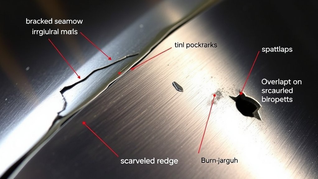
Welding defects are problems in or around a weld that can reduce strength, leak tightness, fatigue life, or appearance. The most common issues include lack of fusion, incomplete penetration, porosity, cracks, slag inclusions, undercut, overlap, burn-through, and distortion. The safest approach is to identify the discontinuity, compare it with the project’s acceptance criteria, correct the cause, and inspect the repaired weld before putting the part into service.
Quick Answer
The most serious welding defects are cracks, lack of fusion, incomplete penetration, and severe porosity. They are usually caused by poor fit-up, low or excessive heat input, contamination, poor shielding gas coverage, wrong technique, or high joint restraint. Prevent them with clean metal, correct joint preparation, a qualified procedure, proper parameters, and suitable inspection.
Key Takeaways
- Cracks are the highest-risk defect because they can grow under stress and are usually rejectable in critical welds.
- Lack of fusion and incomplete penetration are often hidden, so visual inspection alone may not be enough for critical joints.
- Porosity usually points to gas, moisture, or contamination problems, including leaks, drafts, dirty metal, or damp consumables.
- Distortion is controlled before welding through joint design, sequence, tack welds, clamps, and heat-input control.
- A flaw becomes a defect only when it exceeds the acceptance limits in the drawing, welding code, WPS, or inspector’s criteria.
At a Glance
| Time Required | 5–15 minutes for basic visual checks; longer if grinding, repair, radiography, ultrasonic testing, magnetic particle testing, or liquid penetrant testing is required. |
| Difficulty | Beginner for obvious surface defects; intermediate to advanced for code acceptance, root defects, and internal discontinuities. |
| Tools Needed | Good lighting, wire brush, grinder, weld gauge, mirror, flashlight, magnifier, temperature crayons or infrared thermometer, and the applicable WPS or inspection standard. |
| Cost | Low for visual checks; higher for certified inspection, NDT, repair welding, or replacement of a failed part. |
Warning: Do not approve load-bearing, pressure-containing, vehicle, trailer, lifting, or safety-critical welds by appearance alone. Use the applicable drawing, WPS, code, and qualified inspection method. Follow welding safety rules for PPE, fumes, fire prevention, and combustible-material control.
Overview of Common Welding Defects
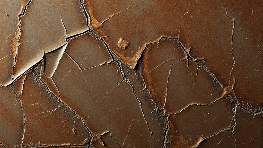
A weld problem is often called a “defect,” but the more accurate term is usually discontinuity or imperfection until it is compared with the acceptance criteria. A small imperfection may be acceptable in one job and rejectable in another, depending on the material, weld type, loading, service conditions, and code requirements. ISO 5817:2023 defines quality levels for imperfections in fusion-welded joints, while AWS D1.1/D1.1M:2025 applies to many structural steel welding projects.
The defects that matter most are the ones that reduce the load path, trap stress, create leak paths, or hide below the surface. That is why lack of fusion, incomplete penetration, porosity, and cracks deserve careful attention. Other common problems, such as undercut, overlap, slag inclusion, excessive spatter, and distortion, can also lead to rejection or rework when they exceed the project limits.
| Defect | What It Looks Like | Common Causes | Best First Fix |
| Lack of fusion | Poor bonding at sidewall, root, or between passes | Low heat, fast travel, dirty metal, poor angle, narrow joint | Clean the joint, adjust heat/travel speed, and improve torch or electrode angle |
| Incomplete penetration | Root not fully fused through joint thickness | Small root gap, thick root face, low current, poor fit-up | Correct joint prep and use enough current for the material thickness |
| Porosity | Pinholes, wormholes, or internal gas pockets | Moisture, oil, rust, paint, drafts, gas leaks, poor shielding | Clean and dry the work, check shielding gas, and shorten arc length |
| Cracks | Linear break in weld metal or heat-affected zone | Hydrogen, high restraint, fast cooling, poor filler choice, crater stress | Stop welding, identify the crack type, remove it fully, and repair under procedure |
| Slag inclusion | Trapped nonmetallic slag between weld metal and passes | Poor cleaning, wrong angle, low heat, narrow groove | Clean between passes and maintain proper bead placement |
| Undercut | Groove melted beside weld toe and left unfilled | High amperage, long arc, fast travel, wrong angle | Reduce heat, adjust travel speed, and pause at the toes |
| Overlap | Weld metal rolls over base metal without fusing | Low heat, slow travel, poor angle, oversized weld | Increase fusion at the toe and avoid piling up metal |
| Burn-through | Hole or collapsed root in thin or overheated material | Too much heat, slow travel, large root gap, thin metal | Reduce heat input and support the root if the procedure allows it |
| Distortion | Warping, bowing, angular change, or misalignment | Uneven heating, shrinkage, poor sequence, weak fixturing | Use balanced sequence, tack welds, clamps, and lower heat input |
By mastering these signs and causes, you can make cleaner welds and catch problems before they become expensive failures. For MIG work in particular, understanding proper heat input helps reduce problems such as poor fusion, undercut, and excessive spatter.
Understanding Lack of Fusion: Causes and Consequences
Lack of fusion happens when weld metal does not properly fuse to the base metal, the joint sidewall, the root, or a previous weld bead. It is dangerous because the weld may look acceptable from the surface while a weak plane remains inside the joint. TWI describes lack of sidewall and inter-run fusion as a weld imperfection linked to joint preparation, welding parameters, welder technique, magnetic arc blow, and surface condition.
Common causes include insufficient heat input, excessive travel speed, poor gun or electrode angle, narrow joint preparation, poor bead placement, magnetic arc blow, and surface contamination such as scale, oil, paint, rust, or moisture. Each cause prevents the molten weld pool from properly wetting and bonding to the metal beside or below it.
The consequences can be serious. Lack of fusion reduces the effective throat or cross-section of the weld, lowers fatigue resistance, creates a path for leaks, and can become a starting point for cracking. It is especially risky in pressure vessels, piping, structural connections, frames, trailers, lifting points, and cyclically loaded parts.
Detecting this defect may require more than a quick look. Visual inspection can catch some surface-breaking lack of fusion, but internal lack of fusion often needs radiographic testing, ultrasonic testing, or another approved NDT method. Ultrasonic testing uses high-frequency sound waves to evaluate internal discontinuities in industrial components.
To prevent lack of fusion, clean the joint to bright metal, confirm the correct groove angle and access, increase current or voltage only within the procedure range, avoid excessive travel speed, hold the right work angle, and place each bead where it can tie into the sidewall. Maintaining proper shielding gas also helps prevent contamination that can interfere with weld quality.
Pro Tip: If the bead sits on top of the joint with a rounded edge and little tie-in at the toes, do not simply add another pass over it. Stop, correct the cause, and remove the unfused area if the weld is already defective.
Exploring Incomplete Penetration: Implications and Solutions
Incomplete penetration, also called incomplete root penetration, occurs when the weld does not extend through the required joint depth at the root. It is most common in groove welds, pipe roots, and joints that depend on full penetration for strength or leak tightness. According to TWI guidance on incomplete root fusion or penetration, joint preparation and welding practice are major factors.
Incomplete penetration can seriously affect welded components in critical applications. It leaves an unfused root area that acts like a notch, reduces the effective section of the weld, and may create a leak path. In pressure piping, tanks, frames, roll cages, and structural welds, this can lead to failed inspection or service failure.
Shielding gas will not fix poor root geometry, but good shielding gas coverage can help prevent contamination-related defects while you correct the root gap, bevel, amperage, and travel speed.
Causes of Incomplete Penetration
Incomplete penetration often comes from a combination of joint and parameter issues. The most common causes include:
- Root opening that is too tight for the process and material thickness.
- Root face or land that is too thick.
- Bevel angle that is too narrow for electrode, wire, or torch access.
- Current or voltage that is too low for the joint thickness.
- Travel speed that is too fast to let the weld pool reach the root.
- Poor electrode or torch angle that pushes heat away from the root.
- Root misalignment or poor fit-up.
- Using a weave pattern where a stringer bead would give better root control.
Because incomplete penetration can be hidden, critical welds may require radiography, ultrasonic inspection, bend testing, macroetch testing, or another method specified by the code, WPS, or inspector.
Prevention Strategies and Techniques
Addressing incomplete penetration requires a proactive approach before the arc starts. Use these strategies:
- Set the root gap, root face, and bevel angle according to the WPS or joint design.
- Use enough current for the material thickness while staying inside the approved range.
- Use a travel speed that allows the weld pool to reach the root without burn-through.
- Keep a steady arc length and correct electrode or torch angle.
- Use backing, purge gas, or root support only when the procedure allows it.
- Clean the root area before welding and between passes.
- For multi-pass welds, remove slag and defects before adding the next pass.
Standards such as ISO 5817:2023 provide quality levels for imperfections in fusion-welded joints, but the exact acceptance limits depend on the job requirements. Always use the drawing, code, contract specification, or inspector’s written acceptance criteria instead of guessing.
Identifying Porosity in Welding: Causes and Effects
Porosity is trapped gas in the weld metal. It may appear as small surface pinholes, elongated wormholes, scattered pores, or hidden internal clusters. A small amount may be acceptable on some noncritical work, but heavy porosity can reduce strength, lower impact toughness, create leaks, and trigger rejection.
TWI explains porosity as gas absorption in the molten weld pool, mainly nitrogen, oxygen, and hydrogen, that becomes trapped as the weld solidifies. Poor shielding gas coverage, air entrainment, moisture, contaminated base metal, damp electrodes, rust, paint, oil, grease, and excessive arc length can all contribute.
Even small shielding-gas problems can matter. TWI notes that about 1% air entrainment in shielding gas can cause distributed porosity.
Start your porosity check with the basics. Clean the base metal, remove paint and oil, store electrodes and flux correctly, check for moisture, inspect the gas hose for leaks, confirm the correct gas type and flow range, block drafts, and keep the nozzle clean. If the weld suddenly becomes porous after running well, check for an empty cylinder, loose gas fitting, clogged nozzle, damaged O-ring, or a fan blowing across the arc.
Identifying porosity early can prevent rework. Surface porosity may be visible after brushing or grinding. Internal porosity may require radiographic testing or ultrasonic testing, depending on the joint and project requirements. Good ventilation is also important for worker safety, but ventilation should not be confused with shielding. Ventilation removes fumes from the breathing zone, while shielding gas protects the molten weld pool. Review proper ventilation and PPE practices before welding or cutting in enclosed or poorly ventilated areas.
Note: More shielding gas is not always better. Excessive gas flow can create turbulence and pull air into the shield. Use the flow range recommended for the process, nozzle size, wire size, and work area.
What You Need to Know About Welding Cracks?
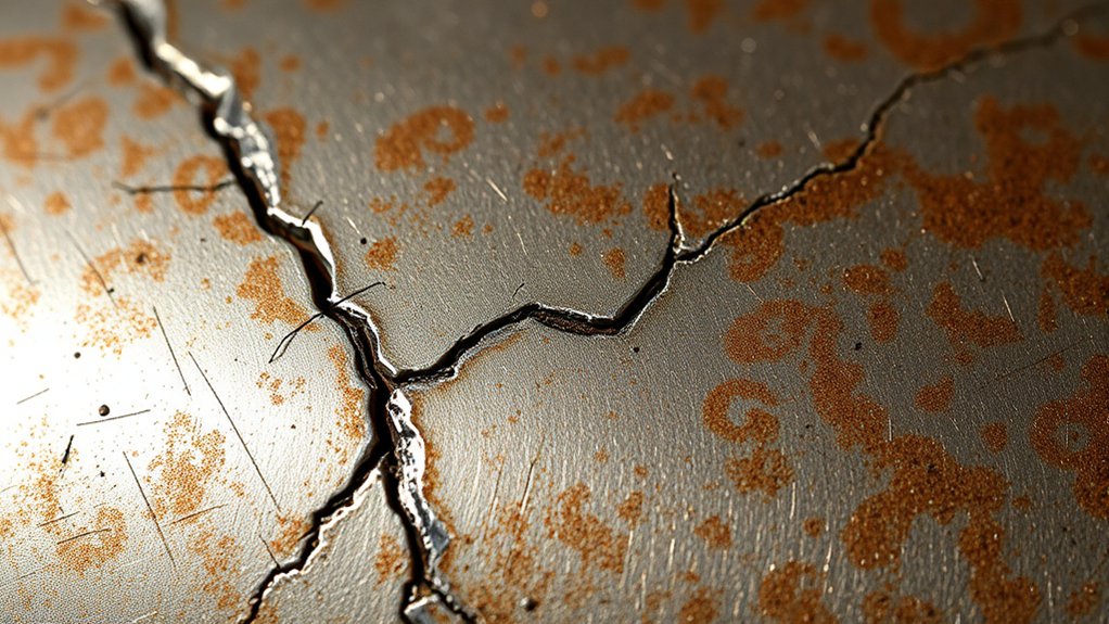
Welding cracks are among the most serious weld defects because they create a sharp stress concentration. A crack can grow under load, vibration, pressure, or thermal cycling. In critical work, cracks normally require removal and repair rather than cosmetic blending.
Cracks may occur in the weld metal, heat-affected zone, crater, root, toe, or base metal. They may be visible immediately after welding or appear later after the part cools. TWI identifies hydrogen cracking, also called cold or delayed cracking, as a risk when diffusible hydrogen, a susceptible microstructure, and tensile stress combine. Preheating, interpass control, and low-hydrogen practice are common prevention tools for susceptible steels.
Correct amperage settings based on metal thickness also matter. Too little heat can cause lack of fusion, while too much heat can increase distortion, undercut, burn-through, or undesirable metallurgical changes.
Types of Cracks
- Hot cracking: Forms during weld metal solidification or at high temperature when shrinkage stress, joint restraint, and susceptible weld chemistry combine.
- Cold cracking: Often develops after welding as the part cools, especially in hardenable steels with hydrogen and restraint.
- Crater cracking: Forms at the end of a weld bead when the crater is left unfilled.
- Toe cracking: Starts at the weld toe, often where undercut, high hardness, or stress concentration exists.
- Root cracking: Starts at the root, often from poor penetration, high restraint, or hydrogen.
- Lamellar tearing: Occurs in the base metal, often in thick plate loaded through its thickness.
Crack detection may require visual inspection, liquid penetrant testing, magnetic particle testing, ultrasonic testing, or radiographic inspection. The correct method depends on material type, crack location, surface condition, and code requirements.
Prevention Strategies
To reduce cracking risk, control the factors that create brittle microstructures, stress, and shrinkage strain. Use the correct filler metal, clean the joint, avoid high restraint where possible, fill craters, maintain proper preheat and interpass temperature, and use low-hydrogen consumables when required. Store low-hydrogen electrodes correctly and avoid welding over moisture, oil, or paint.
Joint design matters too. Avoid sharp transitions, poor fit-up, and undersized welds that concentrate stress. For critical work, follow the qualified WPS and applicable code. If a crack appears, do not weld over it. Remove the crack completely, verify removal if required, and reweld using the approved repair procedure.
Preventing Distortion in Welded Structures
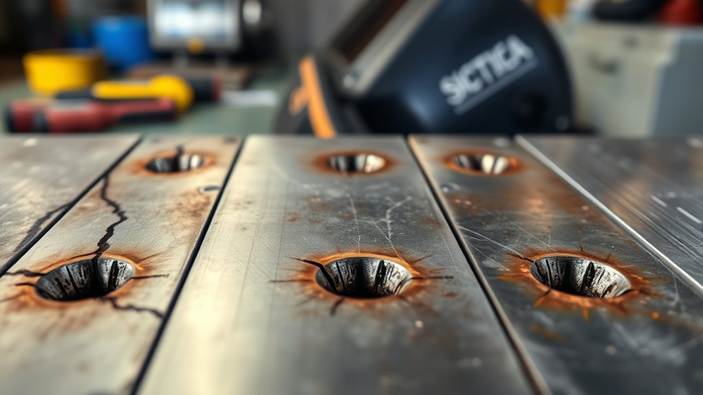
Distortion happens when welded metal expands during heating and shrinks during cooling. If the heat is uneven, the part can pull, twist, bow, or move out of alignment. TWI’s distortion-control guidance emphasizes fabrication techniques such as tack welding, stiffening, process selection, technique, and welding sequence to reduce distortion.
Use these controls before and during welding:
- Use balanced welding sequences for uniform heat distribution.
- Use tack welds, jigs, clamps, or strongbacks to hold alignment.
- Preset parts where the procedure and fit-up allow it.
- Use back-step or skip-welding techniques on long welds when appropriate.
- Reduce unnecessary weld size, overwelding, and excessive reinforcement.
- Use lower heat input settings only if penetration and fusion remain acceptable.
- Shorten weld runs and allow controlled cooling when the job permits it.
- Consider proper electrode selection to help maintain arc stability and avoid excessive heat input.
Preheating can reduce thermal gradients in some materials, but it is not a universal distortion fix. On thin material, too much heat can make distortion worse. Use preheat when the WPS, material, thickness, hydrogen-control plan, or code requires it.
How to Inspect a Weld for Defects
A good inspection starts before the weld is made. Many defects are created by poor fit-up, dirty material, damp consumables, or wrong settings before the first arc is struck.
Products Worth Considering

7piece Fillet Weld Set Gage Rl Gauge

❤WELD GAUGE SET❤ Package Includes 1 x Undercuts Checking Gauge, 1 x Convexity Concavity Checking Gauge, 2 x Instructions, 2 x Pouches. These Gauges with Imperial Measurement Is Suitable for Welding Inspection.

【7 pieces Weld Fillet Gauges】: 7 pieces weld fillet gauges are held by bolt and nut that can be disassembled, each weld gauge can be used to check the size of fillet legs and fillet throats
Before Welding
- Confirm the material, filler metal, shielding gas, and process match the job.
- Check the WPS, drawing, joint detail, weld size, and acceptance criteria.
- Clean the joint faces and remove rust, mill scale, paint, oil, grease, and moisture.
- Confirm bevel angle, root opening, root face, and alignment.
- Check preheat requirements and consumable storage requirements.
- Remove combustible materials and plan ventilation, PPE, and fire watch when needed.
During Welding
- Watch the weld pool tie into both toes of the joint.
- Keep arc length, travel speed, and work angle consistent.
- Clean slag completely between passes.
- Check interpass temperature when required.
- Stop if you see cracking, heavy porosity, slag traps, arc blow, or severe undercut.
After Welding
- Clean the weld so the surface is visible.
- Check bead size, profile, toe blend, undercut, overlap, craters, spatter, and arc strikes.
- Look for surface cracks with good lighting and magnification when needed.
- Use a weld gauge to verify fillet size, reinforcement, undercut depth, and alignment.
- Use PT, MT, RT, UT, or another approved NDT method when visual inspection is not enough.
Warning: Grinding a defect until it “looks better” is not the same as a qualified repair. For critical welds, the defect must be removed to sound metal, inspected if required, and rewelded under an approved repair procedure.
Repairing Welding Defects: When to Fix and When to Reject
The right repair depends on the defect type, depth, location, material, loading, and code requirements. Minor spatter or cosmetic roughness may only need cleaning. Undercut may require blending or repair welding if it exceeds limits. Porosity may require excavation and rewelding if it is clustered, linear, connected to the surface, or beyond acceptance criteria. Lack of fusion, incomplete penetration, and cracks usually require full removal of the defective area before rewelding.
Use this basic repair logic:
- Surface spatter: Remove if it affects fit, coating, appearance, or inspection.
- Minor profile issue: Blend only if the code and drawing allow it.
- Porosity: Remove and reweld if it is excessive, linear, clustered, or leak-related.
- Slag inclusion: Grind or gouge out the inclusion, clean fully, and reweld.
- Lack of fusion: Remove to sound metal and correct the parameter or technique issue before rewelding.
- Incomplete penetration: Repair from the root or remake the joint if required by the design.
- Cracks: Stop-drilling alone is not a complete weld repair in most critical work; remove the full crack and repair under procedure.
If the weld is on a structural, pressure, lifting, vehicle, or life-safety part, ask a qualified welding inspector, engineer, or code-approved repair authority before repairing or accepting it.
Products Worth Considering

Metal Glue Heavy Duty Weld: Its powerful epoxy formula bonds securely to metal, making it ideal for fixing a wide range of metal items, from tools to machinery, offering lasting strength and durability.

[Upgraded] 60W 110V Adjustable Temperature Soldering Iron: Inner-heated ceramic technology makes the soldering kit heat up very quickly (within 1 min).

Frequently Asked Questions
What are the 12 types of welding defects?
Twelve common welding defects are lack of fusion, incomplete penetration, porosity, hot cracks, cold cracks, crater cracks, slag inclusions, undercut, overlap, burn-through, underfill, and distortion. Other issues, such as excessive spatter, arc strikes, poor profile, and misalignment, may also be rejectable depending on the standard.
What are the 7 common welding defects?
The seven common welding defects most welders should know are lack of fusion, incomplete penetration, porosity, cracks, slag inclusions, undercut, and distortion. Each one has different causes, so the fix may involve cleaning, changing heat input, improving fit-up, adjusting travel speed, correcting shielding gas, or using a different welding sequence.
What is F1, F2, F3, and F4 in welding?
The meaning of F1, F2, F3, and F4 depends on the standard, course, or workplace system being used. Some training materials use labels like F1 through F4 for defect groups, but welding codes may use “F-number” for filler-metal grouping in qualification contexts. Always check the specific standard, WPS, or training document before using those labels.
What are the 7 basic types of welding?
Seven common welding processes are SMAW, GMAW, GTAW, FCAW, SAW, resistance welding, and oxyfuel welding. Many shops also use plasma arc welding, laser beam welding, electron beam welding, and friction welding. The right process depends on material, thickness, joint design, productivity, position, code requirements, and finish needs.
Which welding defect is the most dangerous?
Cracks are usually the most dangerous because they create a sharp stress concentration and can grow under load or vibration. Lack of fusion and incomplete penetration are also high-risk because they can hide inside the joint and reduce the effective strength of the weld.
Can you weld over porosity?
Do not simply weld over porosity on critical work. First identify the cause, such as moisture, dirty metal, poor shielding, or a gas leak. Then remove the defective area if it exceeds the acceptance criteria and reweld using corrected settings and clean material.
How do you know if a weld defect is acceptable?
A weld defect is acceptable only if it falls within the limits of the applicable drawing, contract specification, WPS, inspection plan, or code. Do not rely on appearance alone for structural, pressure, vehicle, lifting, or safety-critical welds.
Conclusion
Welding defects are easier to prevent than repair. Lack of fusion, incomplete penetration, porosity, cracks, and distortion usually come from predictable causes: poor cleaning, weak fit-up, wrong heat input, poor shielding, poor technique, high restraint, or skipped inspection. Treat every weld as a system. Prepare the joint correctly, control the heat, protect the weld pool, clean between passes, inspect at each stage, and use the applicable acceptance criteria before calling the weld finished.
Sources
- TWI — Weld defects: lack of sidewall and inter-run fusion — supports lack-of-fusion causes and prevention.
- TWI — Incomplete root fusion or penetration — supports incomplete-penetration causes and prevention.
- TWI — Porosity in welds — supports porosity causes, gas absorption, and shielding issues.
- TWI — Hydrogen cracks in steels: prevention and best practice — supports cold cracking and hydrogen-control guidance.
- ISO 5817:2023 — supports current quality-level context for fusion-welded joint imperfections.
- OSHA 1910.252 — Welding, cutting, and brazing — supports welding safety context for fumes, hazardous materials, and safe operation.




