Choosing the wrong plasma cutter gas can leave heavy dross, rough edges, excess bevel, and worn consumables. The right choice depends on the metal, thickness, plasma system, available shield gas, and the finish you need. This guide explains when to use compressed air, oxygen, nitrogen, F5, H35, and water-shield processes without relying on one-size-fits-all pressure or thickness limits.
Quick Answer
For most handheld plasma cutters, clean, dry compressed air is the practical default. On compatible multi-gas systems, oxygen usually gives the best mild-steel productivity, while nitrogen, F5, H35, or water-shield processes may improve stainless-steel or aluminum cuts. Always use the exact gas combination and settings in the machine’s OEM cut chart.
Key Takeaways
- Clean, dry compressed air is the lowest-cost choice for most air-plasma cutters.
- Oxygen plasma with the approved shield gas is usually the best production process for mild steel.
- Nitrogen, F5, H35, and water-shield processes are mainly used to improve stainless-steel or aluminum results on compatible equipment.
- Gas alone does not determine cut capacity. Use the machine’s recommended-cut, pierce, and severance ratings.
- Wrong pressure, poor air quality, worn consumables, and incorrect travel speed can look like a bad gas choice.
What’s in This Article
- Plasma Gas Quick-Selection Guide
- How Plasma Cutting Works
- Plasma Gas Versus Shield Gas
- Factors That Influence Gas Selection
- Compressed Air
- Oxygen
- Nitrogen
- F5 Gas
- Argon-Hydrogen Mixtures
- Water Shield and Water-Injection Processes
- Material-Specific Recommendations
- How to Choose Plasma Cutter Gas
- Cost and Consumable Considerations
- Equipment Compatibility and Setup Requirements
- Cut Quality Troubleshooting
- Safety and Gas Handling Basics
- Frequently Asked Questions
- Conclusion
- Sources
Plasma Gas Quick-Selection Guide
The table below gives you a starting point, not a substitute for the cut chart supplied with your torch. The same gas may perform differently when you change amperage, consumables, shield gas, material grade, or plate thickness.
| Material or Goal | Practical Starting Choice | Possible Upgrade | Main Limitation |
|---|---|---|---|
| General handheld cutting | Clean, dry compressed air | Nitrogen or F5 only if the system manual approves it | Air may leave a darker or more oxidized edge on stainless steel and aluminum. |
| Fast, clean mild-steel production | Oxygen plasma with the specified shield gas | High-definition or X-Definition oxygen process | Requires a compatible multi-gas system, oxygen-rated consumables, and clean oxygen equipment. |
| Cleaner stainless-steel appearance | Nitrogen or F5, depending on the cut chart | H35, H2Mix, or nitrogen with water shield on supported mechanized systems | Gas cost and travel speed may be less favorable than air. |
| Cleaner aluminum cuts | Air for economy or nitrogen for improved appearance | Nitrogen with water shield or H35 on compatible systems | Process availability depends heavily on the torch and gas console. |
| Thick stainless steel or aluminum | Use the OEM thick-plate process | Often H35 or another hydrogen-containing mixture with nitrogen shielding | Hydrogen-containing gas needs approved equipment, ventilation, and leak controls. |
Note: A “maximum severance” rating describes the thickest material a machine may separate at a slow speed with a rougher edge. It is not the same as the recommended thickness for clean, productive cutting.
Products Worth Considering

10 pcs TIPS (Extended) /10 pcs ELECTRODE (Extended) /10 pcs SHIEDED-CUP/10 pcs GAS RING

Fit for : AG-60 AG-60P SG-55 WSD-60 Plasma cutter torch head

PACKAGE INCLUDED: 5 Pcs Cup-15 Pcs Electrodes-10 Pcs Ring-30 Pcs Tip(Standard)
How Plasma Cutting Works

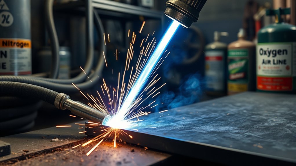
A plasma cutter sends pressurized gas through a narrow torch nozzle. Electrical energy ionizes part of the gas and turns it into a plasma arc.
The arc transfers energy to an electrically conductive workpiece. It melts a narrow path through the metal, while the high-speed gas stream pushes the molten metal out of the kerf. This is why plasma can cut mild steel, stainless steel, aluminum, copper, brass, and other conductive metals.
Many torches first create a pilot arc inside the torch. The arc then transfers to the workpiece after the torch is triggered and the electrical path is established. The exact starting method depends on the system.
Gas choice changes the arc’s heat, chemistry, stability, and interaction with the cut face—but the torch, consumables, current, travel speed, and shield medium still determine the final result.
You can review the basic process in Hypertherm’s plasma-cutting overview.
Plasma Gas Versus Shield Gas
An air-plasma cutter may use compressed air for the entire process. A dual-gas or multi-gas torch can use separate fluids with different jobs:
- Plasma gas: Passes through the nozzle, becomes ionized, and forms the cutting arc.
- Shield or secondary gas: Flows around the plasma jet to cool torch parts, shape or stabilize the process, and influence the cut face.
- Shield fluid: Some mechanized processes use water instead of a gas as the shield medium.
For example, a mild-steel process may use oxygen as the plasma gas and air as the shield gas. A thick stainless-steel process may use H35 as the plasma gas and nitrogen as the shield gas. Naming only the plasma gas does not describe the complete process.
Hypertherm’s stainless-steel process guide explains why the plasma gas, shield medium, system type, and material thickness must be considered together.
Factors That Influence Gas Selection
Choose the gas only after you identify the equipment and the cut you need. The most important factors are:
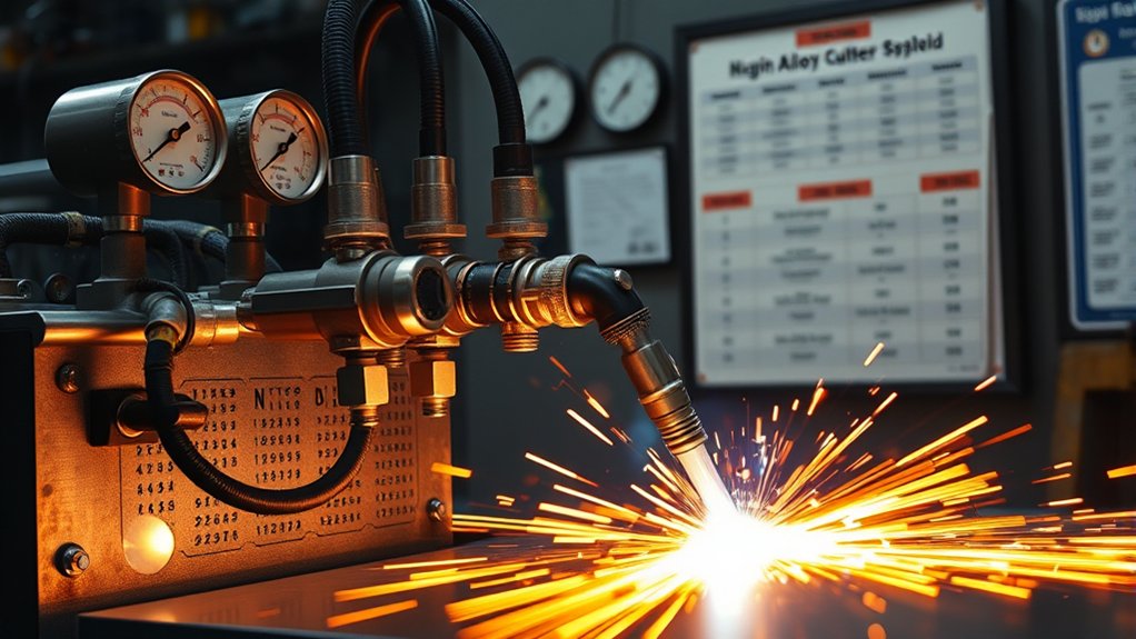
- System type: Determine whether you have an air-plasma, dual-gas, or multi-gas system.
- Base metal: Mild steel reacts differently from stainless steel, aluminum, copper, and brass.
- Material grade and coating: Alloy content, galvanizing, paint, mill scale, and protective coatings can change cut behavior and fume hazards.
- Thickness: Use the exact thickness row in the OEM cut chart.
- Quality target: Decide whether you need basic separation, a production-ready profile, a bright cosmetic edge, or weld preparation.
- Cut speed: A slower premium-gas process may improve appearance but increase cycle time.
- Consumables: The electrode, nozzle, swirl ring, shield, and retaining cap must match the gas and current.
- Operating cost: Include gas, consumables, electricity, rework, grinding, and downtime.
The best gas is the approved process that gives the required quality at the lowest total cost per acceptable part.
Compressed Air
Compressed air is the standard choice for most handheld plasma cutters. It is readily available, costs less than bottled process gas, and can cut mild steel, stainless steel, aluminum, and other conductive metals when the machine is designed for it.
Do not assign air a universal thickness limit. A small air-plasma system and a high-amperage industrial system have very different recommended-cut and severance capacities. Use the rating and cut chart for the exact power supply and torch.
Versatility Across Metals
Air is practical when you cut several metals during the same shift. You do not need to change cylinders or select a different gas for each sheet.
The trade-off is edge chemistry and appearance. Air contains oxygen and nitrogen. Stainless-steel cuts may have a dark gray oxidized surface, while aluminum may show a rougher or more textured cut face than a specialized nitrogen or water-shield process.
If the cut edge will be welded, coated, polished, or used in a corrosion-sensitive assembly, inspect it and complete the cleaning required by your fabrication procedure. A visually clean plasma edge is not automatically ready for every downstream process.
Air Quality and Maintenance
Air must be clean, dry, and free of compressor oil. Moisture or oil can make the arc sputter, increase dross, damage the electrode or nozzle, and shorten consumable life.
Size the compressor for the cutter’s required flow while the machine is operating. A tank may show adequate static pressure but still fail to maintain the required pressure and cubic feet per minute during a long cut.
Use the filter, separator, dryer, hose size, and inlet-pressure range specified by the plasma-cutter manufacturer. A typical shop setup may include a receiver drain, water separator, particulate filter, coalescing filter, and dryer, but the exact filtration requirement is machine-specific.
Inspect and maintain:
- Compressor tank and automatic drains
- Air-line leaks and undersized fittings
- Water separators and filter elements
- Dryer performance
- Hose restrictions and damaged couplings
- Torch consumables and O-rings
ESAB’s manual plasma-cutter guidance identifies air quality, pressure, and flow as major causes of poor cuts and early consumable wear.
Capacity Limitations
As the material approaches the machine’s upper range, travel speed falls and edge quality usually becomes less consistent. You may see a wider kerf, more bevel, heavier dross, and a rougher bottom edge.
Use the manufacturer’s three capacity terms correctly:
- Recommended cut capacity: Productive cutting with acceptable speed and edge quality.
- Pierce capacity: Maximum thickness the system can start through without an edge start.
- Maximum severance: Slow separation near the machine’s absolute limit, usually with more cleanup.
Oxygen

Use oxygen as a plasma gas when a compatible multi-gas system calls for it on mild steel. Oxygen reacts with iron in the kerf and adds heat to the cutting process. This can increase travel speed, lower dross, and produce a clean, weldable edge.
Oxygen is not a universal substitute for compressed air. The torch, gas console, consumables, regulator, hoses, and cut chart must all support the oxygen process.
Best for Mild Steel
For production mild-steel cutting, oxygen plasma with the specified shield gas is often the preferred process. Hypertherm’s gas-selection guide recommends oxygen plasma and air shielding when clean cut quality, low dross, weldability, and productivity are priorities.
- Select the oxygen process in the cut chart for the exact material thickness.
- Install the listed electrode, nozzle, swirl ring, shield, and retaining cap.
- Use the stated plasma and shield gases.
- Set current, pierce height, pierce delay, cut height, and travel speed.
- Verify pressure and flow while gas is moving through the system.
- Make a test cut and inspect dross, bevel, kerf, and edge roughness.
Oxygen Trade-Offs
Oxygen costs more than shop air and may require different consumables. Some oxygen processes also produce different electrode-wear patterns than air or nitrogen processes.
Do not use oxygen as the plasma gas on stainless steel or aluminum unless the manufacturer publishes a specific approved process. Excess oxidation can damage the required edge finish.
Warning: Keep oxygen regulators, valves, hoses, fittings, gloves, and tools free of oil and grease. Use only oxygen-rated equipment, open cylinder valves as directed by the supplier, and keep cylinders secured away from sparks, hot slag, and electrical circuits.
Nitrogen
Nitrogen is used on stainless steel and aluminum when the torch and gas console support it. It can produce a cleaner-looking edge than air and can provide stable performance across several mechanized processes.
Nitrogen is not guaranteed to eliminate dross. On some air-plasma systems, switching from air to nitrogen may improve edge color but require a slower speed or leave more bottom dross. The result depends on the torch, current, consumables, material thickness, and shield medium.
Supported shield choices may include air, nitrogen, carbon dioxide, or water. Never substitute one shield gas for another without a published process chart.
Use nitrogen when:
- The manual lists it for the material and torch.
- A less oxidized stainless-steel or aluminum edge is worth the higher gas cost.
- You have the correct cylinder, regulator, gas purity, hoses, and consumables.
- A test cut confirms acceptable dross, bevel, speed, and surface finish.
Pro Tip: After changing from air to nitrogen, cut a coupon from the same material and thickness. Record the consumable set, pressure, current, travel speed, dross location, edge color, and bevel before changing another variable.
F5 Gas
F5 is a premixed plasma gas containing about 95% nitrogen and 5% hydrogen. It is not the same as H35, and it should not be described as a normal oxy-fuel cutting gas.
Some approved air-plasma and multi-gas systems use F5 for stainless steel. On suitable material thicknesses, it can produce a brighter, more metallic edge than air. The process may cut more slowly and cost more than compressed air.
Use F5 only when all of the following are true:
- The power supply and torch manual list F5 as an approved gas.
- The specified consumables are installed.
- The regulator, fittings, and hoses are compatible with the premixed gas.
- The work area has the ventilation required for a hydrogen-containing mixture.
- The cut chart provides the pressure, flow, current, height, and speed settings.
Do not mix nitrogen and hydrogen in a cylinder or attempt to create F5 in the shop. Purchase the specified premixed gas from a qualified supplier.
Argon-Hydrogen Mixtures

H35 is the common name for a mixture of approximately 65% argon and 35% hydrogen. Compatible mechanized systems often use it for thick stainless steel and aluminum, usually with nitrogen as the shield gas.
Argon helps support a stable plasma column, while hydrogen increases the energy transferred to the cut. On the correct system, H35 can produce a straight cut face and a smooth surface on thick nonferrous material.
| H35 Factor | What It Means |
|---|---|
| Typical mixture | 65% argon and 35% hydrogen |
| Common use | Thick stainless steel and aluminum on approved multi-gas systems |
| Typical shield | Nitrogen, as specified by the cut chart |
| Benefits | High cutting energy, smooth cut face, and strong thick-plate capability |
| Trade-offs | Higher gas cost, specialized equipment, hydrogen controls, and possible bottom dross |
Warning: H35 contains a large percentage of hydrogen. Use it only in a system designed for argon-hydrogen service, follow the manufacturer’s ventilation and leak-check procedures, and never use H35 for underwater plasma cutting. Flammable gas can collect beneath a submerged plate and create an explosion hazard.
Water Shield and Water-Injection Processes
Some mechanized plasma systems use nitrogen as the plasma gas and water as the shield fluid. Other advanced systems use a designed water-injection process that constricts, cools, or shapes the plasma arc.
These are engineered torch processes. They are not made by spraying water near an ordinary air-plasma torch.
Process and Benefits
A compatible water-shield process can improve cut squareness, reduce top-edge heat, and produce a smoother surface on stainless steel or aluminum. Hypertherm’s vented water-injection process, for example, uses nitrogen plasma and water shielding for specific mechanized applications.
The exact result depends on:
- Torch and nozzle design
- Water quality and flow
- Gas-console programming
- Material and thickness
- Current, pierce settings, cut height, and travel speed
- Downdraft or water-table compatibility
Water Shield Versus a Water Table
A water shield is fluid delivered through or around the torch. A water table holds water below or around the plate to collect sparks, cool material, and help manage smoke. Underwater cutting places the plate and arc below the water surface.
These arrangements have different equipment and safety requirements. Some water-shield systems can operate with downdraft extraction rather than a water table, but the cutting-table and filter manufacturers must approve the added moisture.
Do not assume that a water-shield process alone controls all fume exposure. Continue to use the ventilation, extraction, and respiratory controls required for the material and workplace.
Best Material Uses
Water-shield or water-injection processes are most useful when a compatible mechanized system is cutting stainless steel or aluminum and edge squareness, heat control, or appearance justifies the added equipment.
They can suit precision profiles, architectural parts, and components that need less secondary edge finishing. Food-contact or corrosion-sensitive stainless steel may still require cleaning, grinding, pickling, passivation, or another documented finishing process after cutting.
Material-Specific Recommendations
Use these recommendations as a starting point. The OEM cut chart remains the final authority because each system has different gas combinations, consumables, and thickness breakpoints.
| Material | Economical Process | Higher-Quality Option | Important Check |
|---|---|---|---|
| Mild steel | Compressed air on an air-plasma cutter | Oxygen plasma with the approved shield gas | Use oxygen-rated consumables and the exact mild-steel cut chart. |
| Stainless steel | Compressed air for basic cutting | Nitrogen, F5, H35, H2Mix, or water shield when supported | Match the process to thickness, grade, desired edge color, and downstream finish. |
| Aluminum | Compressed air for general work | Nitrogen, nitrogen with water shield, or H35 | Expect process availability and edge appearance to vary widely by system. |
| Copper or brass | Use only the process listed by the machine manufacturer | A specialized nitrogen or high-current process may be available | High heat conductivity can reduce effective capacity and travel speed. |
How to Choose Plasma Cutter Gas
Use this process before buying a cylinder or changing a gas connection:
- Identify the system. Record the power supply, torch model, gas console, firmware version, and current range.
- Confirm approved gases. Read the manual and process chart. Do not assume an air-plasma torch can safely run oxygen, H35, or another specialty gas.
- Identify the material. Record the metal, grade, coating, thickness, and surface condition.
- Define acceptable quality. Decide how much dross, bevel, edge discoloration, roughness, and cleanup the part can tolerate.
- Select the complete process. Match the plasma gas, shield gas or fluid, amperage, and consumable set from one cut-chart row.
- Verify the supply. Confirm gas purity, regulator range, hose compatibility, pressure under flow, compressor capacity, and leak-free fittings.
- Test and document. Cut a coupon, inspect both sides, and record the settings that produce the acceptable part.
Change only one variable at a time during troubleshooting. Changing gas, pressure, speed, current, and standoff together makes it difficult to identify the real cause.
Products Worth Considering

Application: Only Fit Small Acetylene MC tanks with CGA-200 valve (It will not fit larger acetylene tanks, it will not fit any propane tanks and it will not fit any disposable MAPP or Propane Canisters)

【5-in-1 Multifuntion Welder】The AWT welder offers 5 processes: FLUX MIG, GAS MIG,HF TIG,PLASMA CUTTING,and STICK welding, providing a complete solution for various welding and cutting applications. With 110/220V dual voltage, MIG welder perfect for home DIY , farm work and construction sites.

APPLICATION: It can be used with argon, helium and CO2 gas tanks
Cost and Consumable Considerations

Gas price is only one part of plasma-cutting cost. Calculate the total cost per acceptable part or per foot of cut.
Track:
- Gas price and gas flow
- Compressor electricity and maintenance
- Cut speed and machine time
- Number of starts and pierces
- Electrode, nozzle, and shield life
- Grinding, deburring, and edge-finishing time
- Rejected parts and recuts
- Downtime for gas or consumable changes
Compressed air usually has the lowest direct gas cost. Oxygen may cost more but improve mild-steel speed and reduce cleanup. Nitrogen or F5 may justify their cost when stainless-steel appearance matters. H35 is usually reserved for work where thick-plate capability and surface finish outweigh the higher gas and equipment cost.
A cheaper gas is not economical if it doubles grinding time or creates an unacceptable edge.
Equipment Compatibility and Setup Requirements

Verify gas compatibility before connecting a cylinder or changing the shop-air setup. The power supply may accept a gas that the installed torch, console, or consumables do not.
Check the following:
- Approved plasma and shield gases: Use only the combinations listed for the system.
- Consumable part numbers: Match the electrode, nozzle, swirl ring, retaining cap, and shield to the current and gas.
- Gas purity: Use the purity stated by the equipment manufacturer or gas supplier.
- Regulator and hose compatibility: Confirm gas service, pressure range, fitting type, and material compatibility.
- Pressure under flow: Check delivery while the system is purging or cutting, not only when the gas is static.
- Required flow: Confirm that the compressor, cylinder, manifold, or bulk supply can maintain the required flow through the full duty cycle.
- Air treatment: Install and maintain the specified water, particulate, oil, and drying controls.
- Cut-chart settings: Enter the specified current, gas, pierce height, pierce delay, cut height, travel speed, and kerf compensation.
- Consumable condition: Replace damaged parts and inspect O-rings before blaming the gas.
- Firmware and process database: Recheck settings after software, torch, console, or consumable changes.
Warning: Never run an unapproved gas through a plasma torch. The wrong gas can overheat torch parts, damage seals or consumables, create an unstable arc, and expose the operator to fire, explosion, or pressure hazards.
Cut Quality Signs That Your Gas Choice Is Wrong
A bad edge does not always mean you selected the wrong gas. Check the complete setup before changing the process.
| Symptom | Likely Causes | First Checks |
|---|---|---|
| Heavy, easy-to-remove bottom dross | Travel speed too slow, excessive current, wrong cut height, or incorrect process | Compare speed, current, and cut height with the cut chart. |
| Hard high-speed dross or incomplete cut | Travel speed too fast, current too low, low gas flow, excessive standoff, or material beyond productive capacity | Check pressure under flow, speed, current, work lead, and recommended capacity. |
| Excess bevel | Torch not square, worn nozzle, wrong cut direction, poor height control, or unsupported gas combination | Square the torch, inspect the nozzle, verify direction, and check cut height. |
| Arc sputter or rough, wavy edge | Moisture, oil, leaking fittings, restricted flow, damaged consumables, or unstable torch motion | Inspect air quality, filters, leaks, pressure under flow, and consumables. |
| Dark gray stainless-steel edge | Normal oxidation from an air process or excessive heat input | Confirm whether the finish is acceptable; consider an approved nitrogen or F5 process. |
| Short electrode or nozzle life | Wet or oily gas, wrong parts, unsupported gas, incorrect pressure, excessive piercing, or poor shutdown sequence | Verify gas quality, consumable numbers, pressure, pierce height, and shutdown behavior. |
| Arc will not transfer | Poor work connection, paint or rust at the clamp, low gas pressure, damaged torch parts, or excessive torch distance | Clean and secure the work lead, verify gas delivery, and inspect the torch. |
Hypertherm’s dross troubleshooting guide notes that the preferred arc angle can vary by plasma gas. Follow the system’s process-specific instructions rather than using one visual rule for every gas.
Safety and Gas Handling Basics
Plasma cutting combines high voltage, ultraviolet radiation, intense heat, hot slag, noise, compressed gas, and metal fumes. Use the machine manual, workplace safety program, and applicable regulations together.
- Eye and face protection: Use the lens shade and face protection specified for the cutting current and process.
- Skin protection: Wear flame-resistant clothing, gloves, and footwear that protect against ultraviolet radiation and hot slag.
- Ventilation: Use local exhaust or another engineered control for fumes and gases.
- Coated metal: Identify paint, galvanizing, plating, primers, and other coatings before cutting. Remove coatings or use controls required by the safety data and workplace assessment.
- Electrical safety: Keep equipment dry, maintain insulation, use a sound work lead, and do not touch live torch parts.
- Fire prevention: Remove combustibles, control sparks and slag, and keep appropriate fire protection nearby.
- Cylinders: Secure cylinders upright, protect valves, use a cylinder cart, and keep cylinders away from cutting sparks and electrical circuits.
- Regulators and hoses: Use equipment rated for the gas and pressure. Inspect for leaks and damage before cutting.
- Oxygen: Keep oxygen equipment free of oil and grease.
- Hydrogen mixtures: Follow the manufacturer’s ventilation, leak-test, shutdown, and storage instructions.
- Confined spaces: Do not cut in a confined space without an approved entry, ventilation, atmospheric-testing, and rescue program.
OSHA identifies metal fumes, ultraviolet radiation, burns, eye injury, and electrical shock among the main welding and cutting hazards. Its compressed-gas requirements also cover cylinder securing, valve protection, storage, and separation from cutting hazards.
Frequently Asked Questions
What Is the Most Common Gas Used for Plasma Cutting?
Clean, dry compressed air is the most common gas for handheld plasma cutters. It is economical, readily available, and can cut mild steel, stainless steel, and aluminum when the machine is designed for air.
Can You Use Compressor Air for a Plasma Cutter?
Yes, if the plasma cutter is designed for compressed air. The compressor must maintain the required pressure and flow while cutting, and the air must meet the manufacturer’s moisture, oil, and particulate limits.
Do You Need Special Gas for a Plasma Cutter?
Not for most handheld air-plasma cutters. Multi-gas mechanized systems may use oxygen, nitrogen, F5, H35, another hydrogen mixture, carbon dioxide shielding, or water shielding for specific materials and thicknesses.
What Is F5 Gas for Plasma Cutting?
F5 is a premixed plasma gas containing about 95% nitrogen and 5% hydrogen. Some approved systems use it on stainless steel to produce a brighter edge than air. It is different from H35 and should be used only with the listed torch, consumables, settings, and ventilation.
What Is the Difference Between F5 and H35?
F5 is about 95% nitrogen and 5% hydrogen. H35 is about 65% argon and 35% hydrogen. F5 is used by certain stainless-steel processes, while H35 is commonly reserved for thick stainless steel or aluminum on compatible multi-gas systems.
Which Plasma Gas Is Best for Stainless Steel?
Air is the economical choice for general stainless-steel cutting. Nitrogen or F5 may improve edge appearance on approved systems. Thick stainless steel may use H35, H2Mix, or a water-shield process. The best option depends on the torch, thickness, required edge color, dross tolerance, and cost target.
Which Plasma Gas Is Best for Aluminum?
Compressed air is practical for general aluminum cutting. Nitrogen can improve edge appearance, while nitrogen with water shielding or H35 may improve results on compatible mechanized systems. Use the process listed for the exact aluminum thickness and torch.
How Does Moisture in Compressed Air Affect Plasma Cutting?
Moisture can make the arc unstable, increase dross, roughen the cut face, and shorten electrode and nozzle life. Drain the compressor, maintain the separator and filters, repair leaks, and use the air-drying equipment specified by the plasma-cutter manufacturer.
Can You Use Pure Argon in a Plasma Cutter?
Do not use pure argon unless the manufacturer publishes a process for it. Standard thick-plate plasma processes commonly use argon mixed with hydrogen, such as H35, rather than pure argon. An unsupported gas can produce poor cutting and damage the torch.
Does a Water-Shield Process Require a Water Table?
Not always. Some compatible water-shield systems can operate with downdraft extraction. A water table, water shield, and underwater-cutting setup are different systems, so follow the plasma-system, cutting-table, extraction-filter, and water-quality requirements.
Conclusion
The best plasma cutter gas depends on the metal, thickness, machine, consumables, shield medium, and edge-quality target. Clean, dry air is the practical choice for most handheld cutters. Oxygen is usually the leading mild-steel production gas on compatible systems. Nitrogen, F5, H35, and water-shield processes can improve stainless-steel or aluminum results when the equipment supports them.
Do not select gas from a generic thickness rule or pressure range. Start with the OEM cut chart, install the listed consumables, verify pressure and flow under load, and make a test cut. Inspect dross, bevel, edge color, roughness, and consumable wear before approving the process for production.
Sources
- Hypertherm Gas Selection Guide — plasma and shield gas recommendations for mild steel, stainless steel, and aluminum
- Hypertherm Plasma Cutting Stainless Steel Guide — F5, H35, nitrogen, air, and water-shield process guidance
- Hypertherm Plasma Technology Overview — how a plasma arc melts and removes conductive metal
- Hypertherm Dross Troubleshooting — cut-speed and arc-behavior checks for different plasma gases
- ESAB Manual Plasma Cutter Guide — recommended-cut ratings, compressor flow, air quality, and consumable considerations
- OSHA Welding, Cutting, and Brazing Hazards — ventilation, fumes, ultraviolet radiation, electrical, burn, and PPE hazards