
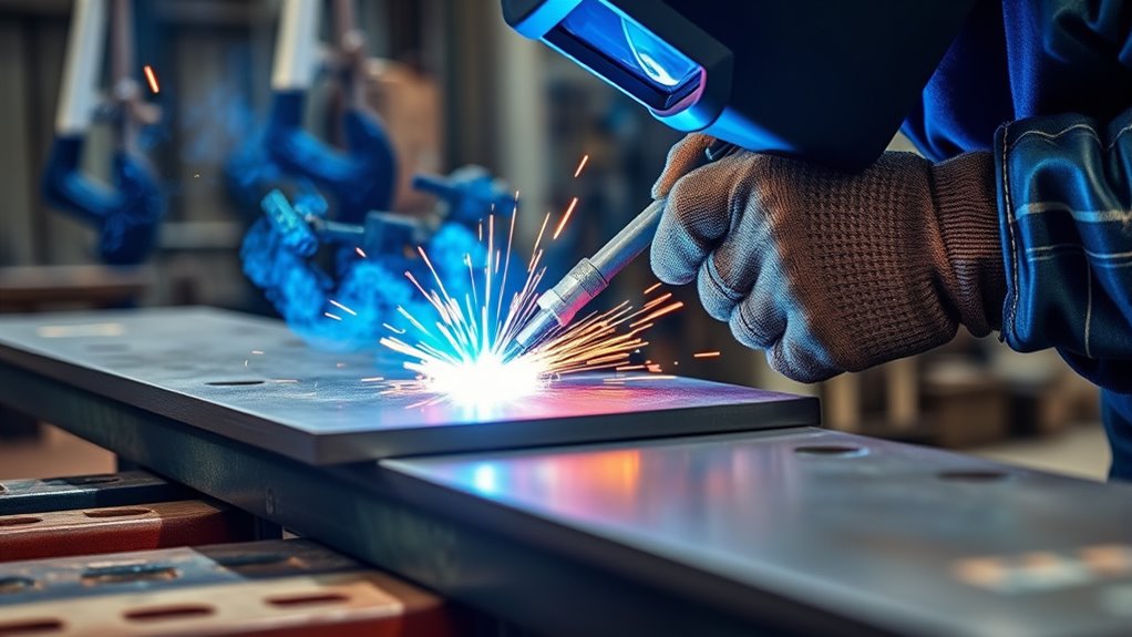
The flat welding position places the weld on the upper side of the joint so the molten pool is supported instead of pulled out of the joint by gravity. It is commonly identified as 1G for groove-weld tests and 1F for fillet-weld tests. This position gives beginners a clear view of the puddle, but sound welds still depend on joint preparation, correct settings, filler selection, and safe technique.
Quick Answer
The flat welding position means the weld is made from above with the weld face approximately horizontal. For plate tests, 1G identifies a flat groove weld and 1F identifies a flat fillet weld. It is usually easier to control than vertical or overhead welding because gravity helps contain the puddle.
Key Takeaways
- Use 1G for a flat groove-weld test and 1F for a flat fillet-weld test.
- A 1G pipe weld usually involves rotating the pipe so welding remains at the top; it is not the same as welding around a fixed pipe.
- Clean, secure fit-up matters as much as position because contamination and movement can cause porosity, lack of fusion, or distortion.
- Set work angle, travel angle, arc length, wire stick-out, and travel speed for the process and joint instead of using one universal technique.
- Follow the welding procedure specification, equipment manual, filler-metal data, and workplace safety rules for any structural or code work.
At a Glance
| Time Required | Varies by joint size, process, preparation, fit-up, tack welding, and inspection requirements. |
| Difficulty | Beginner-friendly for practice beads; code-quality or structural welding requires qualified procedures and training. |
| Tools Needed | Suitable welder and filler, work clamp, joint-cleaning tools, clamps or fixture, welding helmet, gloves, flame-resistant clothing, and ventilation or fume control. |
| Cost | Varies by welding process, metal, filler, shielding gas, and whether equipment is already available. |
What Is the Flat Welding Position?
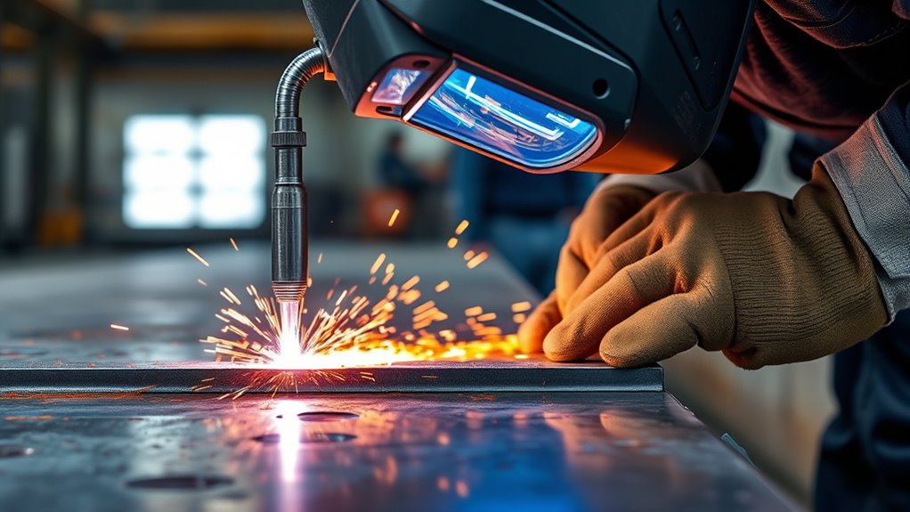
In the flat welding position, the weld is made from the top side and the weld face is approximately horizontal. This orientation gives you direct access to the joint and makes it easier to see the leading edge of the molten pool.
Flat position describes the orientation of the weld, not a promise that the entire workpiece will lie on a perfectly level table.
For plate qualification tests, 1G means a flat groove weld and 1F means a flat fillet weld. The letter identifies the weld type: G for groove and F for fillet. The number identifies the test position.
Pipe terminology needs one extra detail. In a typical 1G pipe test, the pipe axis is horizontal and the pipe rotates, allowing the welder to keep the arc near the top. A fixed horizontal pipe that must be welded around its circumference is normally associated with a 5G test because the welder passes through flat, vertical, and overhead areas.
Flat Welding Position Codes and Joint Orientation
The position code should be read together with the joint type and the applicable welding code or procedure. The following table gives a practical overview for plate work.
| Code | Weld Type | General Position | Main Challenge |
|---|---|---|---|
| 1G | Groove | Flat | Controlling penetration and tie-in without overheating |
| 1F | Fillet | Flat | Keeping equal fusion at both toes |
| 2G / 2F | Groove / fillet | Horizontal | Preventing the pool from sagging toward the lower side |
| 3G / 3F | Groove / fillet | Vertical | Managing a smaller pool while moving up or down |
| 4G / 4F | Groove / fillet | Overhead | Keeping molten metal in the joint and away from the welder |
Note: Position designations used for tests and qualifications can vary by code, joint, and product form. Use the drawing, welding procedure specification (WPS), and governing code rather than relying only on a shorthand label.
Why Choose the Flat Welding Position?
Choose the flat position when the part can be placed safely and the drawing or WPS allows it. Gravity tends to support the molten metal in the joint, so you can usually see the puddle clearly and maintain a steadier bead than in vertical or overhead work.
- Better visibility: You can watch both toes of the bead and the leading edge of the pool.
- Easier puddle control: The weld metal is less likely to sag or fall from the joint.
- Efficient deposition: Some processes and filler metals permit higher deposition rates in flat or horizontal positions.
- Lower physical strain: A well-positioned bench or fixture can reduce awkward overhead work.
- Useful training position: Beginners can focus on arc length, angle, speed, and fusion before moving out of position.
These are practical advantages, not guarantees. Excess heat can still cause burn-through or distortion, and a large puddle can hide poor fusion. Follow the approved parameters and use disciplined heat input management.
Limits of Flat Welding
Flat welding is not always possible or best. Large structures, field repairs, installed pipe, vehicle bodies, and fixed equipment may not be movable. A joint may also require another orientation for access, drainage, distortion control, or procedure qualification.
Do not reposition a part if lifting, rotating, or clamping it creates a crush, fall, or stability hazard. The simplest welding position is not worth an unsafe setup. Also remember that the advantages and disadvantages of welding depend on the process, material, joint design, and service requirements—not position alone.
How to Set Up a Flat Welding Position
- Read the drawing and WPS. Confirm the base metal, joint type, weld size, filler classification, process, position, preheat, polarity, and inspection requirements.
- Inspect the material. Identify coatings, plating, paint, oil, moisture, or unknown residues before grinding or welding. Do not weld a closed container or a container that held flammable material unless an approved cleaning and hot-work procedure has been completed.
- Prepare the joint. Remove contaminants from the weld area and create the specified bevel, root face, root opening, or overlap. Do not grind away required base-metal thickness.
- Position and secure the work. Support the part on a stable table or fixture. Clamp it so the joint cannot move, roll, or close as tack welds shrink.
- Connect and inspect equipment. Check leads, torch, electrode holder, work clamp, gas hoses, regulator, wire path, and consumables. Set the machine to the required polarity settings.
- Set initial parameters. Use the equipment chart, filler-metal data, or WPS for voltage, amperage, wire-feed speed, gas flow, and electrode size. Make a test weld on matching scrap when the procedure permits.
- Tack and recheck fit-up. Place enough tacks to hold alignment. Clean and feather tack ends when the procedure requires them to be incorporated into the weld.
- Adopt a stable body position. Brace your hands or forearms where safe, keep your head out of the fume plume, and make sure you can complete the bead without overreaching.
Warning: Never use oxygen for ventilation. Do not weld in an explosive atmosphere, on an uncleaned container, or in a confined space without the required ventilation, atmospheric testing, attendant, rescue plan, and permit controls.
Products Worth Considering
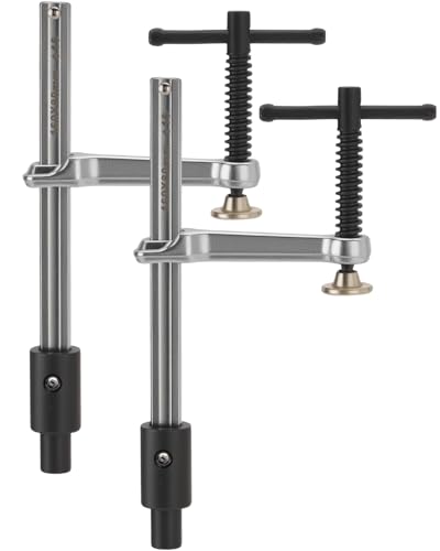
Dual-Pack Power & Efficiency: Double your workspace stability with this essential set of 2 welding table clamps. Specifically designed for standard 5/8-inch (16mm) holes, these welding clamps provide synchronized pressure to keep your frames and metal plates perfectly squared during intense heat.

DESIGNED FOR 5/8" FIXTURE HOLES: Compatible with 5/8-inch (16mm) fixture holes found on most welding tables, providing fast, secure, and reliable clamping for welding and fabrication setups
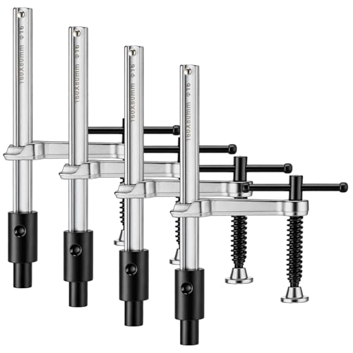
Complete 4 Piece Clamp Set: this practical set includes 4 heavy duty welding clamps, providing excellent value for your workshop; Having multiple clamps on hand allows for efficient simultaneous clamping of complex projects, streamlining your fabrication workflow
Work Angle, Travel Angle, Arc Length, and Speed
Good flat welds depend on several controls working together. The exact values change with the process, filler, joint, and WPS, but these starting points help you understand what to watch.
| Control | Practical Starting Point | What Goes Wrong |
|---|---|---|
| Work angle | About 90 degrees to a flat butt joint; about 45 degrees into a symmetrical T-joint fillet; bias toward the thicker member when appropriate. | Unequal leg size, poor sidewall fusion, undercut, or overlap. |
| Travel angle | Many MIG, flux-cored, and stick applications use roughly 5–15 degrees, but push or drag direction depends on the process and filler. | Too much angle can increase spatter, reduce penetration, and destabilize the arc. |
| Arc length or stick-out | Keep it consistent and within the electrode or wire manufacturer’s recommendation. | An excessive gap can cause spatter, porosity, undercut, unstable transfer, or loss of shielding. |
| Travel speed | Move fast enough to control pool size while allowing both toes to fuse. | Too fast can cause underfill or lack of fusion; too slow can create a wide convex bead, excessive heat, or overlap. |
Miller recommends a 5–15-degree travel angle for common MIG conditions and a 90-degree work angle for a flat butt joint. Its stick-welding guidance also emphasizes a controlled arc length and keeping the arc near the leading part of the pool. See the process-specific manufacturer guidance in the Sources section.
Flat Welding Position Techniques for Better Beads

Watch the puddle and both toes instead of staring only at the arc. The puddle shows whether the weld is tying into each side, becoming too large, or falling behind your travel.
MIG or GMAW
For a flat butt joint, begin with the gun close to 90 degrees to the work and add the specified travel angle. For a symmetrical T-joint fillet, a work angle near 45 degrees helps divide heat between both members. Keep the contact-tip-to-work distance and stick-out length consistent. Follow the machine chart or WPS rather than copying settings from a different wire diameter or gas.
Flux-Cored Welding or FCAW
Use a drag angle unless the wire manufacturer’s instructions state otherwise, and clean slag between passes. Flux-cored welding is not one single outdoor-proof process: self-shielded FCAW can be useful outside, while gas-shielded FCAW can lose shielding in wind. Check the wire classification, polarity, shielding requirements, and permitted positions.
Stick Welding or SMAW
Use the electrode specified for the material and service. A short, controlled arc generally improves bead shape and limits spatter. Many flat stick welds use a slight drag angle. Remove all slag before placing another pass, especially at the toes and crater.
TIG or GTAW
Keep the tungsten-to-work distance steady and protect the molten pool with adequate shielding gas. Add filler at the leading edge without touching the tungsten. TIG puddles can look calm in the flat position, but excess heat can still widen the heat-affected zone, distort thin material, or cause burn-through.
Pro Tip: Before starting a long bead, dry-run the motion with the machine off. Confirm that your hands, cable, helmet, and body position can travel the full joint without a sudden reach or cable snag.
Flat-Weld Technique by Joint Type
Butt and Groove Joints
Center the arc in the groove and watch both sidewalls. Root opening, bevel angle, root face, backing, and pass sequence must match the procedure. Do not assume a wider weave will correct poor fit-up; it can increase heat input and trap slag.
T-Joint Fillet Welds
A symmetrical T-joint often starts with a work angle near 45 degrees. Adjust toward the thicker or harder-to-fuse member when the WPS or joint requires it. Check that the bead reaches both toes and that the fillet size meets the drawing; more weld metal is not automatically better. Review fillet weld sizing before increasing bead size.
Lap Joints
Direct enough heat into the lower member to achieve fusion at the edge of the upper plate. Avoid melting away the upper edge or leaving overlap along the lower toe. Tight, clean fit-up helps prevent the arc from wandering into a gap.
When to Use the Flat Welding Position
Use the flat position when the work can be safely placed or rotated and the procedure permits it. It is common for practice coupons, bench fabrication, plate assemblies, surfacing, and shop work where fixtures can hold the joint at a useful angle.
| Use Case | Why It Fits | Check First |
|---|---|---|
| Beginner practice | Clear view and easier puddle control | Use scrap that matches the process and thickness |
| Bench fabrication | Parts can be clamped and reached from above | Account for tack and weld shrinkage |
| Surfacing or buildup | The pool is easier to contain | Confirm filler compatibility, dilution, pass limits, and heat control |
| Rotated pipe work | Rotation can keep welding near the top | Use safe powered rolls or approved supports; prevent uncontrolled movement |
Flat Welding Position vs. Other Welding Positions
Flat welding usually allows a larger, calmer pool than out-of-position work. Horizontal welding must resist sag toward the lower toe. Vertical welding requires tighter control as the pool moves up or down. Overhead welding places the pool above the welder and usually calls for a smaller, faster-moving pool and stricter protection from falling sparks and metal.
| Position | Puddle Behavior | Typical Adjustment |
|---|---|---|
| Flat | Supported by the joint | Use approved settings and avoid letting the pool become too large |
| Horizontal | Tends to sag toward the lower side | Bias angle and control pool size |
| Vertical | Moves with or against gravity | Use the approved up or down progression and a smaller controlled pool |
| Overhead | Can fall from the joint | Reduce pool size, limit weave, and protect against falling metal |
Products Worth Considering

FLAME-RESISTANT COTTON: Constructed with double layer 7 oz flame-resistant cotton, designed to provide lightweight flame resistance against light sparks & UV exposure.

True Color Clear View: A 3.64" x 1.67" viewing area with 1/1/1/1 optical clarity delivers a true color view for improved visibility and reduced eye strain.
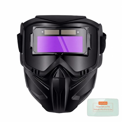
【0.1ms Ultra-Fast Auto-Darkening】Eliminate the split-second hesitation that slows down your production. The instant 0.1ms transition ensures your hands stay exactly where they need to be, keeping your workflow completely seamless. You won't suffer from the cumulative micro-flashes that cause late-day headaches, allowing you to maintain peak focus and speed from the first strike to the final bead.
Common Flat Welding Position Mistakes
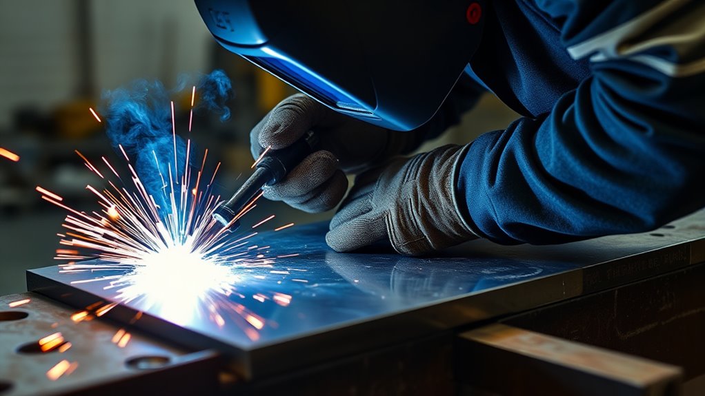
The flat position is forgiving, but it can encourage a puddle that is too large or a travel speed that is too slow. Use the bead and the puddle as feedback.
| Problem | Likely Causes | What to Check |
|---|---|---|
| Porosity | Dirty metal, moisture, gas loss, excessive arc length, drafts, or leaks | Cleanliness, gas flow, hose seals, nozzle condition, stick-out, and wind |
| Lack of fusion or overlap | Low heat at the joint, poor angle, slow travel with a large pool, or arc aimed only at the filler metal | WPS settings, work angle, leading edge of the pool, and joint access |
| Undercut | Excess voltage or amperage, fast travel, excessive angle, or poor pause at the toes | Parameter range, angle, speed, and bead width |
| Slag inclusion | Incomplete cleaning, narrow groove, poor tie-in, or slag running ahead of the arc | Clean every pass and keep the arc at the leading edge |
| Burn-through or distortion | Excess heat, large root opening, slow travel, poor sequence, or weak restraint | Fit-up, settings, tack pattern, sequence, backing, and cooling limits |
How to Check a Flat Weld
After the weld cools to a safe handling temperature, remove slag and spatter as required and inspect the bead in good light. A practice weld should have a reasonably uniform width and profile, clear tie-in at both toes, a filled crater, and no visible cracks, pores, undercut, overlap, or missed areas.
Appearance alone does not prove internal quality. Code work may require dimensional checks, liquid penetrant, magnetic particle, ultrasonic, radiographic, bend, macroetch, or other testing by qualified personnel. Do not declare a structural weld acceptable based only on a smooth-looking bead.
Flat Welding Safety Basics
Flat welding still exposes you and nearby workers to electric shock, hot metal, sparks, ultraviolet and infrared radiation, fumes, gases, noise, compressed cylinders, and fire. Wear a suitable welding helmet and safety glasses, welding gloves, flame-resistant clothing, and protective footwear. Use screens or barriers to protect others from arc radiation.
Clear or shield combustible material and keep suitable fire-extinguishing equipment ready. OSHA requires additional controls in higher-risk hot-work areas, including fire watches in specified conditions and continued monitoring after welding. Follow your employer’s hot-work permit system.
Use local exhaust or other effective ventilation to keep fumes away from the breathing zone. Keep your head out of the plume. Coated, plated, painted, stainless, galvanized, lead-, cadmium-, chromium-, or other alloyed materials may require specific exposure controls. Review the safety data sheets and the applicable OSHA welding requirements.
NIOSH guidance on welding fumes emphasizes controlling fume at the source. Respirators must be selected, fitted, and used through a compliant respiratory-protection program; a casual dust mask is not a substitute for required engineering controls or an approved respirator.
Warning: Do not weld on tanks, drums, piping, or closed sections that may contain flammable, toxic, pressurized, or unknown material. Stop and obtain an approved cleaning, isolation, testing, and hot-work procedure.
Frequently Asked Questions
Is flat welding the easiest position for beginners?
It is usually the easiest position for learning basic puddle control because the joint is visible and gravity helps contain the molten metal. It is not automatically easy, however. Beginners still need correct settings, clean fit-up, stable body position, and supervised practice.
What do 1G and 1F mean in flat welding?
For common plate test designations, 1G means a flat groove weld and 1F means a flat fillet weld. G stands for groove, F stands for fillet, and 1 identifies the flat test position.
Is a 1G pipe weld the same as a flat plate weld?
Not exactly. In a typical 1G pipe test, the pipe rotates while the welder works near the top, keeping the weld in the flat area. A fixed horizontal pipe welded around its circumference is a different test orientation, commonly 5G.
What does the 3 in E6013 mean?
In the AWS E6013 classification, E identifies an electrode, 60 indicates a minimum 60,000 psi tensile-strength class, 1 indicates all-position capability, and the final 3 identifies the coating and current characteristics. Lincoln Electric lists the 3 as a high-titania-potassium coating used with AC or applicable DC current, subject to the product data.
Why is surfacing often done in the flat position?
The flat position helps contain the pool and makes bead placement easier to see, which can support consistent buildup. The surfacing procedure must still control dilution, overlap, pass thickness, interpass temperature, filler selection, and final dimensions.
Can you use MIG, stick, flux-cored, and TIG in the flat position?
Yes, all four processes can be used in the flat position when the equipment, filler classification, shielding, polarity, base metal, and procedure are compatible. A filler marked for limited positions must not be assumed suitable for vertical or overhead work just because it performs well flat.
Should you push or drag in the flat position?
It depends on the process and filler. Stick welding commonly uses a slight drag angle. Many flux-cored wires also use a drag technique. MIG can use push or drag depending on the required bead profile, visibility, penetration, and procedure. Follow the filler and equipment instructions.
Conclusion
The flat welding position is the most accessible orientation for learning puddle control and producing repeatable beads when the work can be positioned safely. Remember that 1G and 1F are test designations for groove and fillet welds, and that 1G pipe normally relies on rotation to keep welding at the top.
For reliable results, prepare the joint, secure the work, use the correct filler and polarity, set parameters from the WPS or manufacturer data, and watch the leading edge of the puddle. Finish with a visual check and any inspection required by the job. Position helps, but procedure, skill, and safety determine whether the weld is acceptable.
Sources
- American Welding Society — How to Pass a Welding Test — position practice and qualification context.
- Miller — Understanding the Basics of MIG Welding for Mild Steel — flat-joint work angles and travel-angle guidance.
- Miller — Five Steps to Improving Your Stick Welding Technique — arc length, travel angle, puddle position, and travel speed.
- Miller — Flux-Cored Welding: The Basics for Mild Steel — FCAW work angles, travel angles, and position adjustments.
- Lincoln Electric — AWS Classifications — electrode classification digits, coating types, and current characteristics.
- Occupational Safety and Health Administration — 29 CFR 1910.252 — fire prevention, PPE, ventilation, confined-space, and hot-work requirements.




