Figuring out how to calculate weld thickness can trip up even experienced welders. It’s one of those things that seems simple until you realize how much depends on getting it right — from metal thickness and joint prep to the type of process you’re running, whether it’s MIG, TIG, or stick welding. Go too thin, and your weld might not have the strength to hold under stress; go too thick, and you’re just wasting filler rods, gas, and time.
The right weld size directly affects weld quality, structural integrity, and even how clean your finished job looks. Knowing how to calculate it properly saves headaches, repairs, and money down the line. Stick around, because in this guide, I’ll walk you through practical, real-world methods to calculate weld thickness accurately — no guessing, just solid results every time.
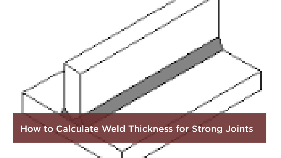
Photo by mitcalc
Why Calculating Weld Thickness Is Crucial in Welding Projects
You’re fabricating a bracket for a conveyor system in a warehouse. The loads are predictable—mostly shear from the belt tension—but if your fillet weld is off by even a sixteenth, that joint could shear clean through under a heavy run. I’ve seen it happen on a job site in Texas, where a rushed calc led to a shutdown and a $10K repair bill. That’s the real-world bite of ignoring weld thickness. It’s not abstract math; it’s the difference between a structure that stands for decades and one that folds when it counts.
At its core, proper sizing ensures weld integrity by matching the deposited metal’s cross-section to the stresses it’ll face. Safety comes first—oversized welds might pass a visual, but undersized ones invite brittle failure, especially in high-vibe environments like off-road rigs.
Material compatibility plays in too: Pairing a thin weld with thick plate pulls heat unevenly, risking hydrogen cracking in carbon steels. And don’t get me started on cost efficiency. Right-sizing saves on electrodes—E7018 rods aren’t cheap—and cuts post-weld grinding or heat treating.
For students hitting the books or industry folks prepping for CWI exams, understanding this ties into broader topics like joint efficiency and allowable stresses. In my shop, I always tell apprentices: Treat every calc like it’s holding your buddy’s life. It builds habits that stick, from hobby welds to code-stamped work.
Understanding the Basics: What Is Weld Thickness?
Weld thickness isn’t some vague term—it’s the measurable dimension that dictates how much filler metal you’re laying down to bridge your joint. In simple terms, it’s the cross-sectional area of the weld that carries the load, whether that’s the leg length on a fillet or the depth of penetration in a groove. Get this wrong, and your whole assembly’s only as strong as its weakest bead.
Think of it like the rebar in concrete: The weld is your reinforcement, and thickness ensures it can take tension, compression, or shear without yielding. For fillet welds—the workhorses of lap and T-joints—thickness often refers to the leg size, that equal-sided triangle you see in cross-section. But the real magic happens at the effective throat, the shortest distance from root to face, which is what codes care about for strength calcs.
In groove welds, like butt joints on pipe, thickness means how deep you penetrate relative to the plate. Full penetration matches the base metal thickness for seamless strength; partial leaves a lip but saves time on thick stock. Why bother with these distinctions? Because mismatched thickness leads to uneven fusion, porosity, or slag inclusions that show up in UT inspections.
From my days running MIG on automotive frames, I learned quick: Thickness isn’t just a number—it’s your buffer against real-world variables like fit-up gaps or thermal expansion. Nail the basics, and the rest falls into place.
Leg Length vs. Effective Throat: What’s the Difference?
Let’s break this down over a couple of cold ones. Leg length is the easy one: Measure from the root along the base metal to the weld face on both toes. For a standard 45-degree fillet, it’s the same on each side—say, a 1/4-inch leg for medium-duty brackets.
But the effective throat? That’s the perpendicular distance through the weld’s heart, roughly 70% of the leg for equal-legged fillets (throat = leg × 0.707). It’s what engineers use for stress calcs because it represents the true load-bearing path. I’ve burned plenty of fillets where the legs looked beefy, but poor convexity made the throat shallow—resulting in a weak spot that popped during a bend test.
Always measure throat with a weld gauge, not just eyeballing legs. It catches convex or concave profiles that skew your strength by 10-15%. And for unequal legs, trig it out: Throat = shorter leg × sin(angle). Keeps you honest on those odd-angle joints in fab shops.
How to Calculate Fillet Weld Thickness
Fillet welds are everywhere—from reinforcing trailer hitches to tying rebar in forms—and calculating their thickness starts with the joint’s demands. You’re not guessing; you’re engineering based on force, material, and code minima. In my experience, most folks undersize here because they skip the load math, leading to convex blobs that look tough but fail early.
The goal? Size the weld so its shear capacity matches or exceeds the applied stress. Start with the basics: Identify shear, tension, or combo loads, then plug into allowable stress formulas from AWS or AISC. For a quick field check on a 1/2-inch plate lap joint under 5,000 lbs shear, you’d aim for a 3/16-inch leg over 12 inches of length. But let’s get precise.
Minimum Sizes Based on Material Thickness
No matter the project, codes like AWS D1.1 set floor values to fight the “quench effect”—thick base metal sucking heat from small welds, causing poor fusion. I once pushed a 1/8-inch fillet on 3/4-inch stock for a quick gate repair; it held visually but cracked under torque. Lesson learned: Always hit the min.
Here’s a handy table pulled from standard practice for carbon steel fillets. Use it as your baseline—bump up for cyclic loads or low-hydrogen needs.
| Base Metal Thickness (inches) | Minimum Fillet Leg Size (inches) |
|---|---|
| Up to 1/4 | 1/8 |
| 1/4 to 1/2 | 3/16 |
| 1/2 to 3/4 | 1/4 |
| Over 3/4 | 5/16 |
For metric minds, that’s 3mm min up to 8mm. Notes: On thicker stuff without preheat, use the thicker part’s thickness for calcs. And for vibes like machinery bases, go 3/16 minimum across the board. This table’s saved my bacon on inspections more times than I can count.
Step-by-Step for Fillet Welds
Ready to crunch numbers? Grab a notepad—I’ll walk you through sizing a fillet for a T-joint on A36 steel, 3/8-inch thick, carrying 4,000 lbs shear over 10 inches.
- Assess the load: Pure shear here, so allowable shear stress for E70XX electrodes is about 21 ksi (0.3 × 70 ksi yield).
- Find required throat: Total force / (length × allowable stress) = required throat. So, 4,000 / (10 × 21,000) = 0.019 inches? Wait, that’s per inch—scale it: Actually, throat t_e = force / (length × 0.707 × leg factor, but simplify: t_e = P / (L × F_v), where F_v is 21 ksi. For our case: t_e = 4,000 / (10 × 21,000) ≈ 0.019 ft? Units: Better in inches—4,000 lbs / (10 in × 21,000 psi) = 0.019 in. Too small; check min table—bump to 3/16 leg (throat ~0.133 in).
- Convert to leg: Leg = t_e / 0.707 ≈ 0.027 in, but min overrides to 3/16 (0.1875 in).
- Check max: Don’t exceed thinner plate minus 1/16 if edge-limited.
- Verify with code: AWS says min 3/16 for this thickness—good.
In the shop, I add a safety factor of 1.5 for unknowns like fit-up. Run multiple passes if over 1/4 leg to avoid cracking. And always bevel edges on thick stock for better penetration.
This method scales to hobby stuff too—like a 1/8 leg on 16-gauge sheet for a toolbox divider. Just plug and play.
Determining Groove Weld Thickness
Groove welds shine in butt and corner joints where full strength is king, like piping runs or vessel seams. Thickness here is about penetration depth: How much root you eat through to fuse plates solidly. I’ve welded miles of Schedule 40 pipe, and skimping on groove depth turns a leak-proof line into a shop flood.
For complete joint penetration (CJP), thickness equals the thinner plate—full throat for max efficiency. Partial (PJP) is groove depth minus root land, ideal for thick plates to cut filler use. Codes demand CJP for high-pressure apps, but PJP saves 20-30% on time for non-critical frames.
Complete vs. Partial Penetration: When to Choose Each
Go CJP when loads demand it—like structural beams under tension. Depth = plate thickness, often with backing or open root. I prepped a 1-inch butt for a tank repair with a 30-degree V-groove; full pen hit 100% efficiency, no backups needed.
PJP suits lighter duty: Depth = calculated throat, say 1/2 the plate for a 3/4-inch joint. Pros: Less distortion, faster. Cons: Lower strength (80-90% efficiency), needs exact groove angles. In fab, I use PJP on trailer crossmembers—saves rods without risking tow failures.
Always factor process: TIG for precision on thin grooves, Stick for beefy ones. And safety? Back gouge incomplete roots to avoid slag traps.
Key Factors That Influence Weld Sizing
Weld thickness isn’t one-size-fits-all—it’s a dance with loads, metals, and your torch hand. Ignore them, and you’re building roulette wheels.
Load Types and Directions
Shear parallel to the throat? Size for 60% of tensile strength. Tension across? Full throat or bust. In my off-road builds, combo loads (shear + moment) demand vector math: Resultant stress = sqrt(shear² + normal²). For a sway bar mount, that meant upsizing from 1/4 to 5/16 leg to handle trail twists.
Cyclic? Add 20% margin per AWS fatigue provisions. Static shop furniture? Stick to minima.
Material Properties and Compatibility
Carbon steel’s forgiving, but stainless or aluminum? Higher conductivity means deeper penetration needs—bump thickness 10-15%. Filler match is key: ER70S-6 for mild steel MIG, 308L for 304SS TIG. Mismatch invites galvanic corrosion or weak bonds.
Thickness ties to yield strength too: Higher Fy plates need beefier welds. I learned hard on a duplex job—ignored compat, got hot cracking. Now, I cross-check with filler charts before striking an arc.
Practical Tips for Accurate Weld Calculations
Theory’s great, but the shop floor’s where calcs live or die. Here’s my toolkit for spot-on sizing.
Prep Work and Joint Design
Cleanliness first: Grind to bright metal, no mill scale stealing heat. For fillets, gap at 1/16 max—too tight starves fusion, too loose wastes filler. Groove joints? Land 1/16-1/8, bevel 30-37 degrees for MIG efficiency.
Fit-up jig every time on repeats; sloppy aligns lead to uneven throats. And preheat: 150°F min on 1-inch plate to slow cooling, preventing brittle zones.
Machine Settings for Optimal Welds
Amps drive penetration—rule of thumb: 1 amp per 0.001 inch thickness for Stick. For a 1/4-inch groove, 100-120A on E7018, travel 8-12 IPM. MIG? Wire speed 200 IPM at 22V for 3/16 fillets on 1/4 plate.
TIG? Pulse for control on thin stuff—50% duty at 80A keeps heat low, precise depth. Test on scrap: Dial till you hit your throat without burn-through.
Travel angle 10-15 backhand for fillets—builds convex for extra throat. And gas: 75/25 Ar/CO2 shields MIG fillets clean.
Common Mistakes When Calculating Weld Thickness (And How to Avoid Them)
That one joint that looked perfect till it didn’t. My biggest flub? Forgetting plate thickness in min calcs on a bridge repair—inspector failed it flat. Cost two days grinding.
Undersizing for shear: Folks chase leg over throat. Fix: Always calc effective area first. Oversizing edges: Max leg = plate -1/16 to avoid overhang cracks—use a radius gauge to check.
Ignoring direction: Vertical shear needs 1.5x horizontal sizing. And cyclic oversight: Add length, not just thickness, for fatigue. Anecdote time: On a wind turbine base, I doubled length on fillets instead of beefing thickness—saved weight, passed NDT.
Visual bias: Convex hides shallow throats. Caliper it. And code drift: AWS updates minima—bookmark D1.1 Table J2.4.
Weld Thickness Across Welding Processes
Process picks your thickness sweet spot. MIG’s fast for fillets—1/4 leg easy on 3/8 plate at 180 IPM. TIG’s king for grooves, precise 1/16 lands. Stick? Forgiving on site, but watch slag for full pen.
Here’s a quick comparison:
| Process | Ideal Thickness Range | Pros | Cons |
|---|---|---|---|
| MIG | 1/8-1/2 inch fillets; 1/4-1 inch grooves | Speed, low spatter | Less control on thin stock |
| TIG | 1/16-3/8 inch precise depths | Clean, versatile alloys | Slower, skill-heavy |
| Stick | 3/16-3/4 inch robust | Portable, outdoors | Slag cleanup, arc stability |
For hobby MIG on exhausts, start 3/16. Pros? TIG for aerospace-thin, Stick for farm repairs. Safety: All need PPE, but TIG’s fumes demand better vent.
Using Tools and Software for Weld Calculations
Pencil works, but apps speed it. AWS weld calculators spit throat from loads quick—input 5k lbs, 12″ length, get 1/4 leg. SolidWorks or Fusion 360 model stresses, auto-size for complex frames.
Field? Pocket weld gauge and stress tables. I use a free AISC app for beam connections—saves hours. But verify: Software assumes perfect fit; real life’s gaps add 10% buffer.
For students, Excel sheets with =SQRT(shear^2 + tension^2) build intuition. Pros, pair with NDT for proof.
Wrapping It Up: Your Path to Confident Weld Sizing
From throat math to process tweaks, you’ve got the blueprint to calculate weld thickness like it’s second nature. Always start with code minima, factor loads and materials, and verify with tools. You’re not just welding; you’re engineering reliability into every joint, whether it’s a backyard arbor or a skyscraper brace.
Now you’re equipped to tackle that next project without second-guessing—grab your gauge, run the numbers, and lay down beads that hold. Prototype on scrap with your exact settings. It’ll catch calc quirks before they bite on the real thing. Go make some metal magic, friend.
FAQs
What Is the Effective Throat of a Fillet Weld?
The effective throat is the shortest distance from the weld root to its face—about 0.707 times the leg length for a standard 45-degree fillet. It’s the key metric for strength, not the leg itself.
How Do AWS Codes Affect Minimum Weld Thickness?
AWS D1.1 sets mins based on base metal thickness to ensure fusion, like 1/8 inch for under 1/4-inch plate. It prevents quench cracks and mandates upsizing for cyclic loads.
What’s the Minimum Weld Size for 1/2-Inch Steel?
For 1/2-inch carbon steel fillets, hit 3/16-inch leg per AWS. Gouges need full or partial pen matching calcs, but always preheat to 50°F min.
Can I Use the Same Thickness Calculation for Aluminum and Steel?
No—aluminum’s conductivity demands deeper pens (20% more throat) and matching fillers like 4043. Steel’s tougher; adjust for alloy specifics.
How Does Joint Prep Impact Required Weld Thickness?
Poor prep like mill scale adds 10-20% to needed thickness for fusion. Clean and bevel properly to hit targets without excess filler or defects.