Let’s call it a strategic investment: selecting a CNC plasma cutter hinges on matching table rigidity, torch capacity, and software workflow to your throughput targets. You’ll assess gantry stiffness, repeatability (<±0.1 mm), and bed size, then pair a torch and power source to your material thickness, pierce amps, and duty cycle. Finally, validate CAD/CAM/controller integration for nesting, kerf compensation, and motion tuning. Miss any link in this chain, and performance slips—here’s how to avoid that.
What Is a CNC Plasma Table?
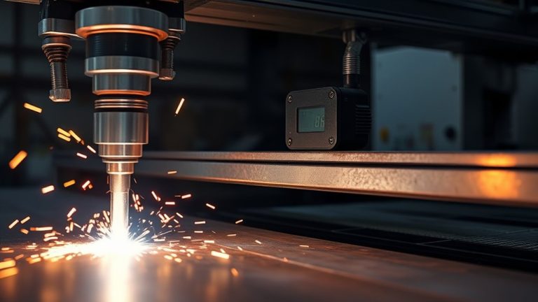
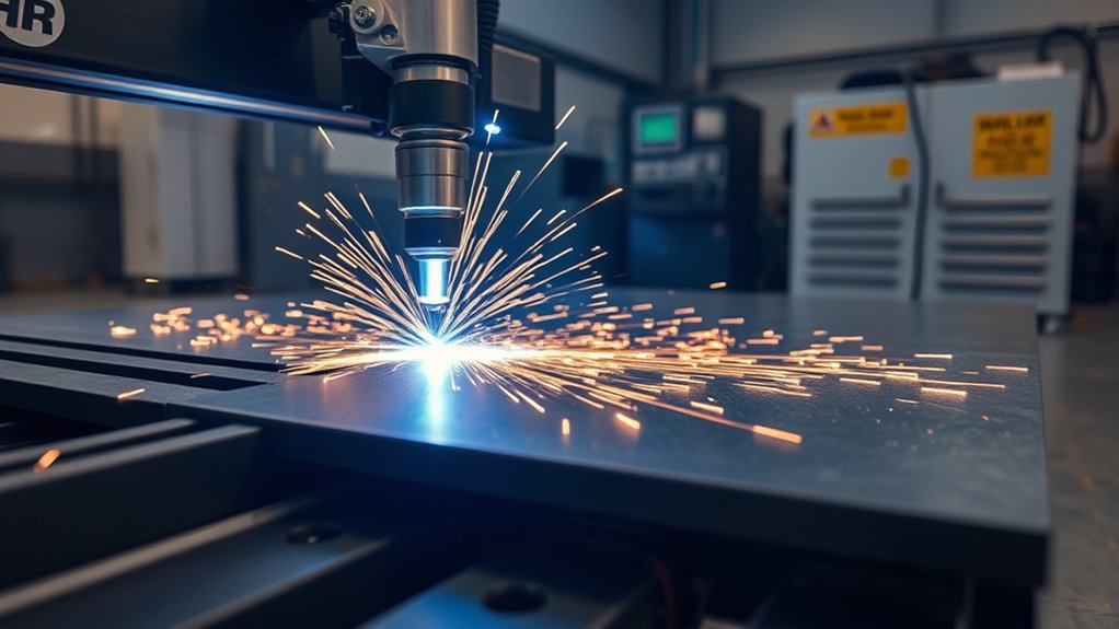
Although it looks like a simple flatbed, a CNC plasma table is an automated cutting system that drives a plasma torch along X‑Y axes on a gantry to cut electrically conductive materials with speed and accuracy.
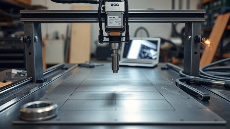
You load plate onto steel slats that stabilize the workpiece and absorb heat, then import toolpaths from CAD/CAM to define contours, pierces, and lead-ins. The controller synchronizes motion and amperage to maximize cutting precision while protecting edges from excess heat input.
You’ll tune feed rates up to 500 inches per minute depending on thickness and material compatibility—mild steel, stainless, aluminum, or copper.
Automatic torch height control samples arc voltage and adjusts standoff in real time, maintaining kerf consistency, reducing dross, and extending consumable life.
Closed-loop motion, proper kerf compensation, and nesting strategies minimize scrap and cycle time. The result is repeatable, high-throughput profiling of complex geometries with quantified tolerances and predictable surface quality.
Plasma Table vs. Plasma Cutter
You’ll compare roles: the plasma cutter generates a high-velocity plasma jet for material separation, while the table provides motion control, stability, and safety systems.
You’ll map components: torch, power supply, and consumables vs. table frame, gantry, drives, torch height control, and fume extraction.
You’ll assess performance by pairing CAD/CAM-driven torch motion with tables capable of up to 500 ipm, matching power source and mechanics for cut quality and throughput.
Roles and Functions
While both components work as a single cutting system, the plasma cutter and the plasma table serve distinct roles. You rely on the cutter for energy delivery and arc control; it creates the high-velocity plasma jet that severs conductive stock. You depend on the table for motion control, fixturing, and thermal management that drive cutting accuracy and material compatibility. CAD/CAM commands position the torch on a gantry with X-Y travel and Z-height control, maintaining standoff to stabilize kerf width and edge quality. Tables routinely coordinate speeds approaching 500 ipm, outperforming manual methods, while slats or water beds support, absorb heat, and reduce distortion. The result is precise, automated profiling where the cutter executes and the table orients, stabilizes, and repeats.
| Component | Primary Function |
|---|---|
| Plasma Cutter | Generates plasma arc and cuts |
| Plasma Table | Supports workpiece and aligns motion |
| Gantry System | Executes X-Y travel |
| Z-Axis Control | Maintains torch height |
| Software Control | Automates toolpaths and speed |
Table vs. Torch Components
Building on roles and functions, separate the table’s motion platform from the cutter’s arc source to optimize both accuracy and cut quality.
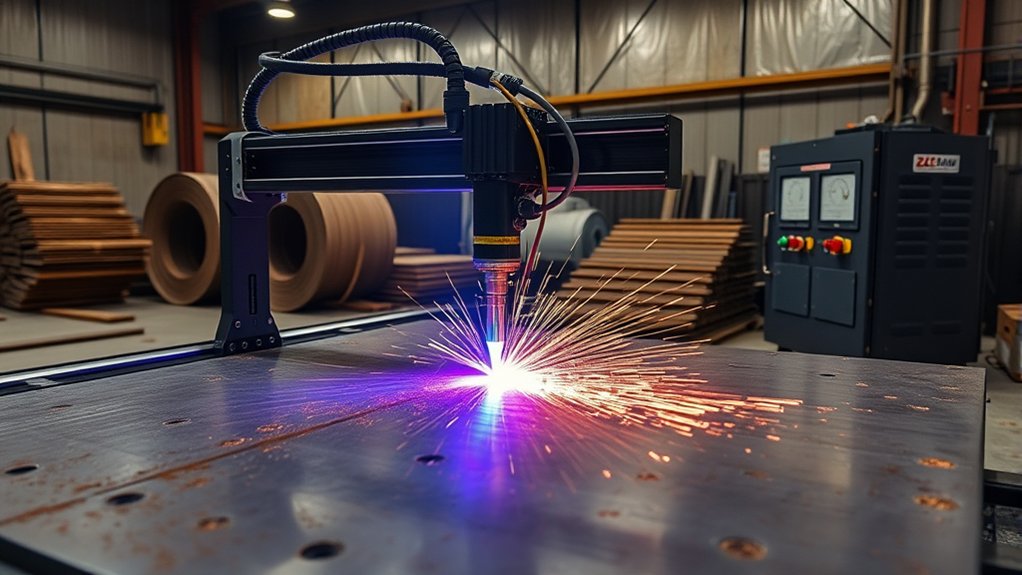
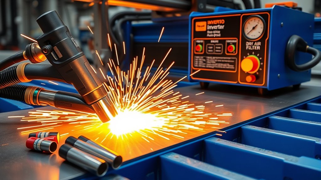
The table provides a stable plane with steel slats that absorb heat; the cutter houses the torch that creates a 30,000°C+ ionized gas jet. Your CNC table drives X/Y/Z with a gantry, executing CAD toolpaths, while the plasma unit governs arc start, amperage, and gas flow.
Match table materials to duty cycle and part weight; match torch types and starting methods (high-frequency vs. pilot arc) to material and thickness. Together, they determine kerf, dross, and throughput—up to 500 ipm.
- Select rigid frames and slat layouts
- Validate gantry stiffness and drives
- Pair amperage to thickness
- Choose reliable arc start
- Tune height control and gas settings
Key Features to Evaluate
Before committing to a CNC plasma table, define the technical requirements that will govern performance, uptime, and cut quality. Start with table size: match 2’x2’ to prototyping, scale to 4’x8’ or 5’x10’ for full sheets to minimize handling and fixturing time. Specify a CNC control that’s intuitive; PC-based interfaces suit small shops and reduce training overhead. Prioritize automatic torch height control (ATHC) to stabilize arc voltage, preserve edge integrity, extend consumable life, and sustain cutting speed on warped sheets. Verify CAD/CAM compatibility—native DXF import, clean toolpath post-processing, and nesting—so design intent translates to accurate motion. Finally, align output power to material thickness: e.g., ~12 A for 1/8” trials, ~60 A approaching 7/8” capacity.
| Decision Lever | Risk if Ignored | Payoff When Optimized |
|---|---|---|
| Table size | Bottlenecks, re-cuts | Fewer setups |
| Control UX | Operator errors | Faster onboarding |
| ATHC | Edge taper, wear | Stable cut quality |
| CAD/CAM | Broken paths | Accurate parts |
| Amperage | Incomplete cuts | Rated thickness, speed |
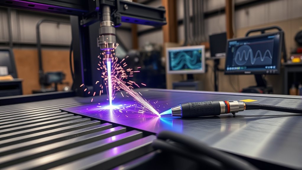
Choosing the Right Torch and Power Source
How do you match a torch and power source to your cut envelope without compromising signal integrity or uptime?
Start by sizing amperage to material: plan roughly 1/8 in additional thickness per +10A. For example, pair an IPT65 with 65A machines and an IPT80 with 85A units to guarantee torch compatibility and stable arc geometry.
Prioritize blowback start over high-frequency start to minimize EMI that can corrupt CNC I/O lines. Validate CNC trigger input and “arc ok” feedback so your controller can start reliably and monitor arc continuity.
Target power source efficiency and a 100% duty cycle at your working amperage to prevent pauses.
- Match amperage to thickness: +10A ≈ +1/8 in capacity
- Use IPT65 (65A) or IPT80 (85A) for proven torch compatibility
- Prefer blowback start to reduce EMI and protect signal integrity
- Verify CNC trigger and “arc ok” wiring and logic levels
- Specify 100% duty cycle at set amperage for continuous runs
Software Workflow: CAD, CAM, and Controller

Discipline defines a reliable plasma workflow: you move from CAD for geometry creation, to CAM for toolpath planning, to the controller for execution.
You design in CAD, constrain geometry, and export clean DXF to preserve layers and units. Validate arcs and node counts to avoid fragmented paths. This upfront rigor supports software integration downstream.
In CAM, assign kerf width, pierce delay, and cut heights, then generate lead-ins/lead-outs aligned with material thickness and feature size. Use inside/outside offsets, tabbing, and cut sequencing to control heat input.
Simulate to verify pierce order and feed consistency, then post-process to your controller’s dialect.
Controller software loads the CAM file, applies motion profiles, and manages torch on/off, THC, and feed overrides.
You monitor arc OK, pause for consumable checks, and rely on emergency stop if conditions drift. Tight integration across CAD, CAM, and controller is what yields repeatable throughput and cutting precision.
Top Models and Buying Considerations

With your CAD→CAM→controller workflow defined, match hardware to those process demands by prioritizing table size, motion capability, and power.
Select table dimensions that fit parts and floor space: common footprints span 2’×2’ to 5’×10’. A 5’×10’ bed supports full sheets and nested jobs, minimizing handling.
Verify motion system rigidity and torch height control; automated THC maintains arc voltage for consistent kerf and consumable life.
Shortlist proven models. For example, the STV Motorsports SparX510 5×10 integrates cable management and THC, delivering accurate cuts in materials up to 3/4 inch.
Align plasma power to material: 60 A reliably pierces near 7/8 inch; step up amperage for thicker stock or higher duty cycles.
Target cutting speed capability up to 600 ipm to sustain throughput, but validate real speeds on your alloys and thicknesses.
Favor controllers with integrated CAD/CAM for faster programming and fewer handoffs.
- Match table dimensions to part envelope and nesting.
- Confirm straightness, backlash, and repeatability specs.
- Require automated torch height control.
- Size plasma amperage to thickness and duty cycle.
- Verify achievable cutting speed on your materials.
Frequently Asked Questions
How Loud Are CNC Plasma Cutters and What Hearing Protection Is Needed?
They’re typically 95–120 dBA at the operator. You implement hearing conservation: wear 25–33 NRR earmuffs or combine 20–25 NRR plugs with muffs for higher attenuation. Measure noise levels, limit exposure duration, and document controls per OSHA/NIOSH guidelines.
What Ventilation or Fume Extraction Setup Is Required for Small Shops?
You need source-capture fume extraction or a water table plus make-up air. Specify 600–1,000 CFM at the torch, 350–500 FPM duct velocity, MERV 15–HEPA filtration, and interlocked ventilation systems; maintain negative pressure and verify airflow with anemometer readings.
How Much Power and Electrical Service Do Typical Systems Require?
You’ll need 30–60A at 240V single-phase; larger tables demand 80–100A or 480V three-phase. Shocking, right? Verify power requirements, electrical specifications, duty cycle, inrush current, breaker sizing, conductor gauge, and grounding; consult NEC and manufacturer datasheets.
What Routine Maintenance Schedules and Consumable Lifespans Should I Expect?
Expect daily inspections, weekly lubrication, and monthly alignment checks; follow manufacturer maintenance intervals. Electrode/nozzle consumable durability averages 1–3 hours arc-on; shields/swirl rings 10–20 hours. Replace filters quarterly. Monitor arc voltage, cut quality, and pierce counts to predict replacements and optimize uptime.
How Do I Estimate Operating Costs per Cut, Including Gas and Consumables?
Treat each cut like a taxi meter: compute energy kWh, gas flow×time, and consumable wear per pierce/inch via cost analysis. Use consumable pricing, duty cycle, feed rate, and scrap rate; validate with timed test coupons.
Conclusion
You’re ready to choose with confidence: match table size to your largest sheet, verify rigidity and motion accuracy, and confirm torch-power source compatibility for your target thickness range. Prioritize software that streamlines CAD-to-CAM-to-controller with nesting, simulation, and post reliability. Validate cut quality via kerf width, taper, and dross metrics. As the adage goes, measure twice, cut once—use spec sheets, duty cycles, and repeatability data to benchmark options. Align budget to uptime, consumables cost, and support responsiveness.