Cold lap is a common name for a weld-overlap or lack-of-fusion condition at the weld toe. It happens when deposited weld metal rolls onto the base metal or an earlier bead without melting into it. The result may look filled from the outside, but the unfused edge can reduce the effective weld area and create a place where a crack may start.
Preventing cold lap requires more than simply increasing the machine setting. You must match the welding parameters to the material, joint, filler metal, position, and approved procedure. Clean the joint, use a stable arc, control the puddle, and confirm that both edges of the bead blend smoothly into sound metal.
Quick Answer
Prevent cold lap by using enough heat for the joint, keeping a steady travel speed, holding the correct work and travel angles, and welding only on clean metal. Watch the leading edge of the puddle: it should melt into both joint faces and leave smooth toes, not a rolled lip or sharp line.
Key Takeaways
- Cold lap is a fusion problem: weld metal extends over the surface without fully melting into the base metal or previous pass.
- Check the entire setup: heat, travel speed, arc length, angle, polarity, filler size, shielding, and joint preparation work together.
- Watch the puddle edges: both toes should wet smoothly into the joint without a rolled lip or sharp line.
- Do not rely on appearance alone for critical work: internal lack of fusion may require an approved inspection method.
- Remove the defect before repair: another bead can bury cold lap rather than correct it.
At a Glance
| Time Required | About 10–30 minutes for basic inspection and setup checks; repair time varies with weld size and inspection requirements |
| Difficulty | Beginner to identify obvious overlap; intermediate or advanced to repair structural or code-controlled welds |
| Tools Needed | Correct PPE, inspection light, wire brush or grinder, machine chart or WPS, measuring tools, and matching scrap metal |
| Cost | Usually low for setup correction; removal, re-welding, and professional nondestructive testing can add substantial cost |
What Is Cold Lap and Why Is It a Problem?
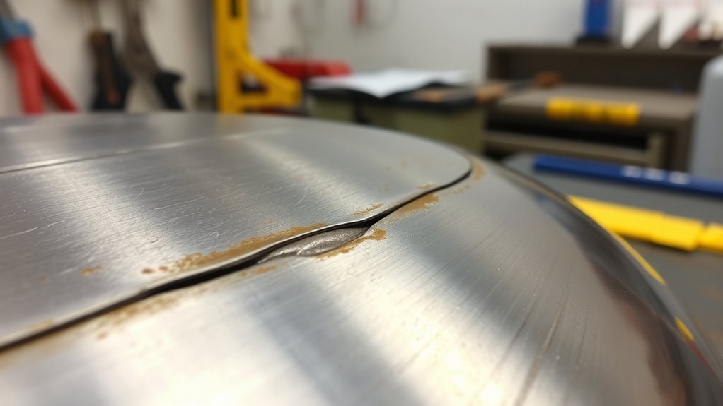
In shop language, cold lap usually describes overlap or visible lack of fusion at a weld toe. Weld metal extends past the intended toe and lies on the adjacent surface without fully fusing to it. Lincoln Electric discusses this condition as cold lapping in short-arc MIG welding.
A cold-lapped bead may have a rolled edge, raised lip, or sharp line where the weld should blend into the base metal. The same basic problem can occur between passes when a new bead fails to melt into the edge of the previous bead.
Cold lap is closely related to lack of fusion, but the terms are not identical. Cold lap or overlap normally describes a visible surface condition. Lack of fusion can also occur at a root or sidewall where it cannot be seen after welding. A surface indication may therefore be only part of a larger fusion problem.
The condition matters because the intended joint is not fully bonded across the affected area. It can reduce the effective weld size, trap slag or contamination, create a leak path, and form a stress concentration. The actual risk depends on the weld location, loading, material, service conditions, and acceptance criteria.
Visual assessment is the first step, but it does not prove that the weld is sound below the surface. On brackets, frames, trailers, pressure-related work, lifting equipment, vehicle parts, or other critical components, the applicable drawing, code, welding procedure specification, and inspection plan control whether the weld is acceptable. Selecting an appropriate electrode diameter also helps keep the current range and bead size suitable for the joint.
Warning: Do not ignore suspected cold lap on a weld that supports weight, contains pressure, experiences repeated vibration, or affects vehicle, lifting, structural, or equipment safety. Stop work and follow the approved inspection and repair procedure. Do not hide the area with another bead, body filler, paint, or grinding.
Cold Lap vs. Similar Welding Defects
Several welding discontinuities can look similar from the surface. Correct identification matters because each one has different causes and repair requirements.
| Condition | What It Means | Typical Surface Clue |
| Cold lap or overlap | Weld metal extends over the adjacent surface without fusing to it | Rolled lip or sharp line at the weld toe |
| Lack of sidewall fusion | Weld metal fails to fuse with a groove face, joint wall, or earlier pass | May be invisible after the joint is filled |
| Incomplete penetration | The weld does not reach or fuse through the required root area | An unfused root line may be visible only from the back or by testing |
| Undercut | A groove is melted beside the weld and left unfilled | A depression beside the toe rather than a rolled lip |
| Slag inclusion | Nonmetallic slag is trapped within or between weld passes | May appear as a dark line or remain hidden inside the weld |
Penetration describes how far the weld reaches into the joint or root. Fusion describes whether the molten weld metal has bonded to the base metal or previous pass. A weld can have penetration at the root and still lack fusion along one sidewall.
Understanding Cold Lap: Causes and Effects
Cold lap forms when the arc and molten puddle do not melt the intended joint surface before weld metal flows over it. Low heat input is one common cause, but it is not the only one. Incorrect travel speed, poor arc placement, excessive deposition, contamination, unsuitable joint geometry, and loss of puddle control can produce the same result.
Common clues include a raised or ropey bead, rolled toes, a straight unfused line, uneven wet-out, or slag trapped beside an overlap. These signs suggest that the bead has not blended smoothly into sound metal. They do not show how deep the condition extends.
Cold lap can also form between layers of a multi-pass weld. Slag, oxide, spatter, or an unfavorable bead profile can prevent the next pass from reaching the edge of the earlier bead. Cleaning and shaping each pass is therefore part of fusion control, not merely cosmetic work.
Machine duty cycle does not directly determine fusion. However, exceeding the rated duty cycle may interrupt the work or trigger thermal protection. Let the machine cool as directed and investigate any unexpected change in arc output before continuing.
Common Causes of Cold Lap
- Insufficient heat at the joint: The arc does not melt enough of the base metal or previous pass.
- Travel speed is too fast: The arc moves away before the joint face melts and the puddle ties in.
- Travel speed is too slow: An oversized puddle can move ahead of the arc or bury the arc behind deposited metal.
- Incorrect work angle: Heat is directed toward one joint member while the other side remains cold.
- Excessive travel angle: The arc pushes or drags metal without concentrating heat where fusion is required.
- Arc length or stickout is wrong: Heat and arc force become less controlled.
- Voltage, current, or wire feed is mismatched: The bead builds up without adequate wet-out.
- Wrong polarity or shielding setup: Arc characteristics may not match the electrode or wire requirements.
- Surface contamination is present: Rust, paint, oil, grease, zinc, moisture, oxide, and heavy mill scale interfere with a clean weld pool.
- Weaving is excessive: The puddle edges cool or become covered before the arc returns to them.
- Filler size is unsuitable: A wire or electrode outside the recommended range can make current and deposition harder to control.
- Joint access or fit-up is poor: A narrow groove, uneven gap, poor bevel, or misalignment prevents the arc from reaching the required surface.
- Interpass cleaning is incomplete: Slag, oxide, spatter, or an unfavorable bead contour blocks the next pass.
Welding Safety Before Troubleshooting Cold Lap
Correcting cold lap may involve welding, grinding, gouging, wire brushing, or removing coatings. Each step can expose you to hot metal, sparks, ultraviolet radiation, electrical hazards, noise, flying particles, and hazardous fumes. Follow your workplace hot-work procedure and the equipment manufacturer’s instructions.
- Wear suitable PPE: Use the correct welding helmet shade, safety glasses, flame-resistant clothing, gloves, hearing protection, and protective footwear.
- Control fumes at the source: Use suitable ventilation or local exhaust and keep your head out of the fume plume. Review NIOSH welding-fume guidance for exposure considerations.
- Remove fire hazards: Protect nearby surfaces from sparks and hot slag, and use a fire watch when the hot-work procedure requires one.
- Identify coatings and base metals: Paint, zinc, lead, cadmium, stainless steel, and other materials can create process-specific exposure hazards.
- Do not weld sealed containers or closed hollow sections: Clean, vent, purge, and test them under an approved procedure before heat is applied.
- Treat confined spaces as specialized work: Atmosphere testing, ventilation, entry controls, rescue planning, and trained personnel may be required.
- Secure the work: Support the part before removing weld metal so the joint cannot shift, fall, release stored energy, or collapse.
Warning: Never weld, cut, or grind a tank, drum, pipe, hollow member, or container that may have held a flammable, combustible, toxic, or pressurized substance unless it has been cleaned, opened, tested, and released under an approved hot-work procedure. Review OSHA welding and hot-work requirements.
How to Identify Cold Lap in Welds
Begin by allowing the weld to cool safely, removing slag and loose spatter, and cleaning the area well enough to see the toes and transitions. Use bright lighting and an inspection mirror where access is limited. Do not grind away the suspected indication before its location and length have been recorded.
- Look for a rolled toe: The edge appears to lie on the plate rather than flow smoothly into it.
- Look for a sharp continuous line: A line at the bead edge may mark the boundary between deposited metal and an unfused surface.
- Check bead contour: A tall, ropey, excessively convex, or piled-up bead may indicate low heat or poor puddle placement.
- Compare both toes: Fusion on one side and overlap on the other often point to an incorrect work angle.
- Inspect starts, stops, and tie-ins: These locations are vulnerable when the joint is not hot enough or the arc is moved before the puddle is established.
- Check between passes: Look for sharp valleys, trapped slag, oxide, or bead shapes that prevent access to the sidewall.
- Review weld size: An oversized fillet may encourage excess deposition and poor toe fusion. Understanding the intended fillet weld size helps avoid unnecessary buildup.
Slag that is difficult to remove is not proof of cold lap. Electrode type, bead shape, current, arc length, and technique all affect slag release. Treat trapped slag beside a rolled toe as an additional clue, not a stand-alone test.
Note: A smooth-looking surface does not prove complete fusion. Grinding, painting, or adding another pass can hide an indication without removing the underlying discontinuity.
When Visual Inspection Is Not Enough
Visual inspection can find surface overlap, undercut, cracks, incorrect profile, and other visible conditions. It cannot reliably confirm internal sidewall or root fusion. Critical welds may require additional inspection selected by the governing code or qualified inspector.
- Liquid penetrant testing: Detects suitable surface-breaking discontinuities on clean, nonporous materials. It does not show buried lack of fusion.
- Magnetic-particle inspection: Detects surface and near-surface indications in ferromagnetic materials. It is not suitable for aluminum or austenitic stainless steel.
- Ultrasonic testing: Can detect some internal planar discontinuities, but results depend on orientation, geometry, calibration, access, procedure, and operator qualification.
- Radiographic testing: Can reveal internal volumetric conditions and some planar conditions, but orientation and joint geometry affect detectability.
- Macro etch or section testing: Shows fusion and penetration on a cut sample but is destructive.
- Bend testing: Can expose weak fusion in a test coupon, but it is normally performed to a defined qualification or test procedure.
Troubleshooting Cold Lap by Bead Appearance
| What You See | Likely Checks | Correction to Test on Scrap |
| Tall, ropey bead with poor wet-out on both sides | Low voltage or current, excessive wire feed for the voltage, fast travel, long stickout, or cold base metal | Return to the recommended parameter range, shorten stickout if required, and keep the arc on the leading edge |
| Overlap on one toe only | Incorrect work angle, poor access, joint misalignment, or arc aimed at the opposite member | Correct the work angle and direct the arc at the unfused joint face |
| Large convex bead with the arc buried behind the puddle | Travel too slow, deposition too high, or angle placing the arc behind the leading edge | Increase travel speed slightly, reduce deposition within the approved range, or reposition the arc |
| Intermittent cold lap after arc changes | Wire feeding, ground connection, stickout, gas coverage, polarity, or power-supply issue | Inspect equipment and consumables before changing technique |
| Defect appears at starts or restarts | Arc moved before a fluid puddle formed, restart placed on slag, or tie-in not remelted | Clean the restart, establish the puddle, and remelt the previous bead edge before advancing |
Adjusting Heat Settings to Avoid Cold Lap
Use the parameter chart supplied with the welding machine, the filler-metal manufacturer’s data, or the approved WPS as your starting point. The correct setting depends on the process, material grade, thickness, joint, position, electrode or wire size, polarity, shielding gas, transfer mode, and required weld size.
Do not raise the setting blindly. Too little heat can cause lack of fusion, but excessive heat can cause burn-through, undercut, excess penetration, distortion, spatter, loss of mechanical properties, or an oversized heat-affected zone. Maintaining a suitable arc length helps keep the arc stable and directed into the joint.
Proper Heat Input
Proper heat input gives the arc enough energy and time to melt the required joint surfaces without overheating the work. The useful sign is not the machine number alone. It is a controlled puddle whose leading edge melts into both sides of the joint.
- Start with approved data: Use the machine chart, electrode or wire data, welding procedure, and material requirements.
- Verify polarity: Match the power-source connection to the filler-metal instructions.
- Check the actual joint: Thickness, bevel, root opening, fit-up, backing, and position affect the setting.
- Control arc length or stickout: Excessive distance can reduce arc control and change the current delivered to the joint.
- Test on matching scrap: Use the same material type, thickness, joint orientation, filler, shielding gas, and position when possible.
- Inspect the test bead: Look for smooth toe transitions, proper profile, stable arc behavior, and evidence of fusion.
- Change one factor at a time: Small controlled changes make it easier to identify the true cause.
Voltage and Amperage Balance
Voltage and current affect the arc and bead differently. On common constant-voltage MIG equipment, wire feed speed largely controls welding current, while voltage strongly affects arc length and bead profile. The two settings must remain within a compatible operating range.
Voltage that is too low for the wire feed can create a stubbing arc, narrow bead, excessive buildup, and poor wet-out. Voltage that is too high can produce a wide or unstable arc, spatter, and undercut. Wire feed that is excessive for the selected voltage may deposit metal faster than the joint can melt.
For stick and TIG welding, amperage, arc length, electrode size, travel speed, and joint geometry have different relationships. Use process-specific guidance rather than copying a MIG correction to another process. Miller’s guidance on common MIG weld defects identifies low voltage, low wire feed, and excessive travel speed as causes of lack of fusion.
Pro Tip: Make a short test weld on matching scrap and watch the front edge of the puddle. If the bead remains tall and does not wash into the sides, stop and check the recommended parameter range, arc placement, stickout, travel speed, and angle before changing multiple settings at once.
Maintaining Ideal Travel Speed During Welding
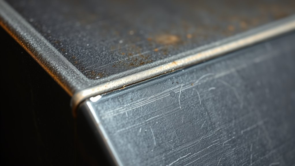
Travel speed controls how long the arc acts on each part of the joint and how much filler is deposited per unit of length. Moving too fast can leave the joint face unmelted. Moving too slowly can create an oversized puddle that flows ahead of the arc or covers the area that still needs heat.
The correct pace changes with the process, joint, position, material, and parameter range. Watch the puddle rather than trying to copy one fixed hand speed. Proper heat input and travel speed must work together.
Consistent Speed Control
- Establish the puddle first: Do not move away from the start before the joint faces begin to melt.
- Watch the leading edge: Keep the arc close enough to the front of the puddle to melt the joint rather than only heating deposited filler.
- Maintain a steady pace: Avoid sudden stops and surges that create changing bead size and heat input.
- Support your hands: Use a comfortable stance, dry run, prop, guide, or repositioning plan where appropriate.
- Use controlled pauses only when required: A brief sidewall pause may help some joints, but a long pause can create excess buildup or undercut.
- Stop when visibility is lost: Clean the lens, change position, improve lighting, or correct access rather than welding without seeing the puddle edges.
Impact of Travel Angle
Work angle points the electrode or torch between the joint members. Travel angle tilts it forward or backward along the direction of travel. An incorrect work angle commonly causes fusion on one toe and overlap on the other. An excessive travel angle can reduce arc control and direct heat away from the required surface.
A travel angle of about 5 to 15 degrees is a common starting range for many basic MIG applications, but it is not a universal welding rule. Miller’s MIG welding guidance for mild steel recommends that general range and warns that much larger angles can increase spatter, reduce penetration, and destabilize the arc.
Use the angle required by the welding process, filler manufacturer, joint, position, and WPS. A fillet weld may require a work angle near the center of the joint, while unequal material thickness may require more heat directed toward the thicker member.
Push vs. Pull Technique and Cold Lap
There is no single push-or-pull rule for every arc-welding process.
- Solid-wire MIG: Push, pull, or near-perpendicular techniques may be used in some applications. Push commonly improves visibility and creates a flatter bead, while a drag angle may change penetration and bead profile. Follow the transfer-mode and filler guidance.
- Flux-core welding: A drag or pull technique is normally used so slag stays behind the arc. Miller’s flux-core process guide recommends dragging the gun.
- Stick welding: The correct direction and angle depend on the electrode, position, and progression. Keep slag behind the leading edge of the puddle.
- TIG welding: Use a short, controlled arc and add filler without blocking the arc from the joint faces.
If overlap forms at the leading edge or one toe, check whether the arc is buried in the puddle, aimed away from the joint face, or moving before the sidewall melts. Make a small correction and inspect the next test bead.
Choosing the Right Filler Metal
Filler metal must be suitable for the base material, welding process, polarity, required strength, service temperature, corrosion conditions, and governing procedure. Diameter also matters because each wire or electrode has a recommended operating range.
A joint is not sound simply because weld metal fills the space. The bead must fuse into the required base metal and previous passes, with a smooth transition at both toes.
- Confirm material compatibility: Match filler classification and mechanical properties to the base material and procedure.
- Use the correct diameter: Select a wire, rod, or electrode that can operate within the available current range and joint size.
- Check polarity: Some electrodes and flux-core wires require a specific connection to perform correctly.
- Follow shielding requirements: Use the specified shielding gas, flow range, nozzle condition, and wind protection.
- Store filler correctly: Keep wire and electrodes clean and dry, and follow any low-hydrogen storage or reconditioning requirements.
- Do not substitute casually: A similar-looking filler may have different strength, usability, hydrogen, or service properties.
- Follow manufacturer data: Use the recommended parameter range and review the appropriate welding rod selection guidance for the process.
Products Worth Considering

Model: ER70S-6 TIG Welding Rod The ER70S-6 is a gas-shielded, copper-plated carbon steel welding rod (welding wire) designed for low-alloy and carbon steel. Perfect for TIG welding, it ensures strong, durable welds and is a must-have in your welding supplies.

E71T-GS FLUX CORE WIRE: This self-shielding, AWS E71T-GS flux-cored wire excels due to its advanced core design, delivering exceptional arc stabilization and high feedability for effortless welding. The core also incorporates powerful deoxidizing agents, ensuring clean, reliable welds even when welding through light rust or mill scale.

er308l stainless steel tig welding rods 1 16 x 16 1 6mm tig filler rod thin stainless sheet tubing handrail kitchen equipment low splatter corrosion resistant stainless steel welding wire tig welding accessories gta w argon arc
Best Practices for Preparing Your Metal
Prepare the joint so the arc can reach clean, correctly shaped metal. Remove oil, grease, paint, rust, moisture, heavy mill scale, and other contaminants from the weld area. Use a cleaning method that is suitable for the base metal and does not leave harmful residue.
Check the groove angle, root face, root opening, alignment, backing, and access before welding. Thick sections may require a bevel or other joint preparation so the arc can reach the root and sidewalls. Preheat only when required by the material specification, approved WPS, filler guidance, or qualified engineering instruction. Thickness alone does not determine the correct preheat.
Galvanized coatings may interfere with fusion and create hazardous zinc-containing fumes. Remove coating from the required weld area using an approved method, but do not assume that surface removal eliminates the need for ventilation and exposure controls. Review safe methods for removing zinc coating from galvanized steel.
Metal Prep Checklist Before Welding
- Identify the material: Confirm the alloy, coating, thickness, and any heat-treatment restrictions.
- Remove contaminants: Clean oil, paint, rust, moisture, zinc, oxide, and heavy scale as required.
- Use dedicated tools where needed: Prevent cross-contamination of stainless steel, aluminum, and other sensitive materials.
- Check edge preparation: Verify the bevel, root face, opening, and land dimensions.
- Confirm fit-up: Correct misalignment and uneven gaps before adding weld metal.
- Clamp and support the work: Prevent movement while allowing for the planned weld sequence and distortion control.
- Verify access: Make sure the torch or electrode can reach the root and both sidewalls at the required angles.
- Clean between passes: Remove slag, oxide, spatter, and grinding debris before the next bead.
Good preparation improves fusion, makes the puddle easier to read, and reduces the need to compensate with excessive heat or filler metal.
Warning: Coated, painted, oily, galvanized, stainless, lead-bearing, or otherwise treated metal may create hazardous fumes or decomposition products. Use suitable source capture, ventilation, work practices, and respiratory protection when required. Never use chlorinated solvents near arc welding or other hot work.
Effective Welding Techniques to Prevent Cold Lap
Keep the arc directed at the metal that must melt. The front edge of the puddle should reach both joint faces before you move forward. The following controls help prevent deposited metal from rolling over a cold surface:
- Use approved settings: Begin within the recommended range for the material, filler, process, and position.
- Keep the arc near the leading edge: Do not let the electrode remain buried far behind an oversized puddle.
- Maintain the correct work angle: Divide heat between the joint members as required.
- Control arc length or contact-tip distance: Keep it within the process and filler recommendations.
- Limit weaving: Use only the width and sidewall pause permitted by the procedure or electrode guidance.
- Use stringer beads when appropriate: Several controlled beads may provide better access and fusion than one wide weave.
- Clean every pass: Remove slag, oxide, and spatter before placing the next bead.
- Shape unfavorable bead valleys: Grind or dress a profile that allows the next pass to reach sound metal when the procedure permits it.
- Control deposition: Do not make a bead larger than the joint requires.
- Inspect as you go: Correct a developing pattern before it continues through the entire weld.
- Match electrode behavior to the setting: Review the appropriate stick welding amperage chart and filler instructions.
Cold Lap Prevention by Welding Process
- MIG welding: Check voltage, wire feed speed, polarity, contact-tip-to-work distance, travel speed, work angle, shielding gas, wire feeding, and ground connection. A tall ropey bead may indicate a cold parameter combination, excessive stickout, or poor arc placement.
- Stick welding: Check electrode classification, polarity, amperage, arc length, work angle, travel angle, and slag position. Do not allow slag to run ahead of the arc.
- Flux-core welding: Use the specified polarity and shielding gas, maintain the recommended drag angle, control stickout, and clean all slag between passes.
- TIG welding: Establish a fluid puddle before adding filler, keep a short controlled arc, direct heat at both joint faces, and avoid feeding rod in a way that blocks the arc.
Preventing Cold Lap at Starts, Stops, and Between Passes
Starts, stops, and restarts are common fusion-risk areas because the joint may be cold, the previous crater may have an unfavorable shape, or slag may remain at the tie-in.
- At the start: Establish a stable arc and molten puddle before moving forward. Use run-on tabs when the qualified procedure requires them.
- At a stop: Fill the crater as required and avoid leaving a steep edge that the next pass cannot reach.
- At a restart: Remove slag and contaminants, position the arc on sound weld metal, and remelt the previous bead edge before advancing.
- Between passes: Clean the entire bead, inspect the toes, and remove any overlap rather than burying it.
- In vertical or overhead work: Reduce puddle size and use the process-specific progression, angle, and parameter range needed to keep the arc at the leading edge.
- At multi-pass sidewalls: Place each bead so the next pass has access to the previous toe and groove face.
How to Fix Cold Lap After It Happens
Do not place another bead over suspected cold lap. The added weld may hide the surface line while leaving lack of fusion trapped underneath. The normal repair concept is to remove the affected weld metal, prepare a sound joint, correct the cause, and re-weld under the applicable procedure.
- Stop and assess the part: Determine whether the weld is structural, pressure-containing, fatigue-loaded, code-regulated, or subject to an approved repair plan.
- Mark the indication: Record the visible length, location, side, pass, and surrounding bead condition before grinding.
- Support and isolate the component: Remove loads, stored energy, flammable materials, and other hazards before cutting or grinding.
- Remove defective metal: Grind, machine, gouge, or cut out the affected area using a method allowed by the material and repair procedure.
- Confirm sound metal: Continue removal until the suspect line, trapped slag, and unfused profile are gone. Additional inspection may be required.
- Restore joint geometry: Prepare a groove that allows the replacement weld to reach the root and sidewalls.
- Clean the area: Remove grinding debris, oxide, oil, slag, moisture, and contamination.
- Correct the cause: Adjust the parameter combination, angle, arc placement, travel speed, fit-up, filler, polarity, shielding, or access problem.
- Re-weld under the approved procedure: Watch the leading edge and verify smooth tie-in at both toes.
- Inspect the repair: Perform the visual and additional examinations required for the component.
Pro Tip: A shiny ground surface does not prove the entire discontinuity is gone. Remove enough material to expose a continuous sound profile, then inspect the prepared cavity before depositing the repair weld.
Products Worth Considering

VALUE PACK: Total 40PCS including 12PCS x 40 Grit, 12PCS x 60 Grit, 8PCS x 80 Grit, 8PCS x 120 grit, 4-1/2 Inch Diameter, 7/8 Inch Arbor, Type #27, 13300RPM maximum speed

●High carbon steel chipping hammer,heat treated,10-1/2-Inch overall length.1-1/16" width chisel to remove welding slag faster
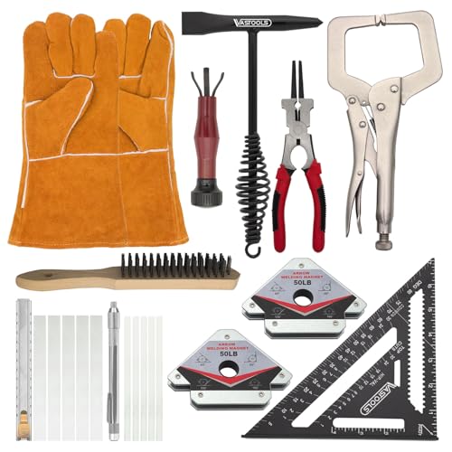
●High carbon steel chipping hammer,heat treated,10-1/2-Inch overall length.1-1/16" width chisel to remove welding slag faster,with 11"Heavy duty wire brush
When to Use a WPS or Qualified Inspector
General troubleshooting advice is suitable for practice coupons and noncritical shop work. It does not replace a qualified welding procedure, drawing, code, engineer, manufacturer repair manual, or inspector.
Stop and obtain qualified guidance when the weld involves:
- Pressure vessels, pressure piping, boilers, tanks, or gas systems.
- Building structures, bridges, lifting points, cranes, hoists, or fall-protection anchors.
- Vehicle frames, suspension, steering, rollover protection, or safety restraints.
- Aircraft, rail, marine, mining, or regulated industrial equipment.
- High-strength, heat-treated, cast, hardenable, dissimilar, or unidentified materials.
- Repeated fatigue, impact, severe vibration, low-temperature, corrosive, or high-temperature service.
- A production weld governed by a drawing, customer specification, code, or WPS.
A qualified inspector can determine the applicable acceptance criteria and select an inspection method that is suitable for the material and expected discontinuity.
Insights From the Welding Community
Experienced welders can often spot bead-profile and technique problems from clear photos or a live demonstration. Peer feedback is useful when it is based on the full setup rather than appearance alone. Include the process, material, thickness, joint, position, filler, polarity, gas, machine settings, and travel direction when asking for help.
Community feedback should be treated as a troubleshooting aid, not an acceptance decision for critical work. Approved procedures, inspection requirements, and manufacturer instructions still control the final weld.
Common Troubleshooting Tips
- Photograph the full joint: Include the bead, both toes, starts, stops, and surrounding base metal.
- Record the setup: Note voltage, amperage or wire feed, polarity, filler classification and size, gas, flow, and stickout.
- Share the welding position: A setting that works flat may not control the puddle overhead or vertical.
- Compare a test coupon: Repeat the same joint on scrap and change one variable at a time.
- Cut and inspect practice samples: A macro section or bend test can reveal issues that a surface photo cannot.
- Ask process-specific questions: MIG, TIG, stick, and flux-core defects may require different corrections.
- Separate fusion from appearance: A smooth bead can still be unfused, and a less attractive practice bead may still show better tie-in.
Related defects can point to a broader setup problem. For example, understanding worm tracks in flux-core welding helps separate gas marks from fusion defects.
Shared Success Stories
Successful corrections usually have one feature in common: the welder identifies the actual cause instead of turning up the machine and hoping for a different result. A one-sided overlap often improves after correcting work angle. A tall ropey MIG bead may improve after returning voltage, wire feed, stickout, and travel speed to a compatible range. Interpass cold lap often improves after slag removal and better bead placement.
Clear before-and-after samples are useful when the material and setup remain the same. Practice on matching scrap lets you compare one controlled change at a time. Preheat should be used only when the material, filler, WPS, or qualified instruction requires it—not as a universal fix for a cold bead.
Wrapping Up: Tips to Avoid Cold Lap
Cold lap prevention depends on creating and maintaining fusion at every required joint surface. Use the correct process data, prepare the joint, establish a stable puddle, and watch the leading edge rather than only the finished bead behind the arc.
Prevent cold lap by directing a stable arc into clean joint faces, using compatible parameters, controlling deposition and travel, and confirming smooth fusion at every toe and tie-in.
- Follow the correct procedure: Use the machine chart, filler data, drawing, and WPS that apply to the job.
- Prepare the joint: Clean the surfaces and provide enough access to the root and sidewalls.
- Use compatible settings: Match voltage, current, wire feed, polarity, gas, and filler diameter.
- Control travel: Avoid outrunning the arc or burying it behind an oversized puddle.
- Control both angles: Use the correct work angle and a process-appropriate travel angle.
- Keep the arc where fusion is needed: Watch both toes and the front of the puddle.
- Limit excessive weaving: Use controlled stringers or permitted weave widths.
- Clean between passes: Remove slag, oxide, and unfavorable overlap before continuing.
- Inspect early: Stop when a repeated line or rolled toe first appears.
- Remove defects before repair: Never rely on another bead to fuse through hidden cold lap.
When welding galvanized steel, follow safe coating-removal and ventilation practices and review the risks associated with zinc fumes. Removing visible coating does not replace exposure controls.
Frequently Asked Questions
How Do You Prevent Cold Lap in Welding?
Use a compatible welding-parameter range, clean and prepare the joint, hold the correct work and travel angles, and maintain a steady pace. Keep the arc near the leading edge of the puddle and confirm that both weld toes melt smoothly into the joint faces.
What Causes a Cold Lap?
Common causes include insufficient heat at the joint, excessive or very slow travel, incorrect arc placement, poor work angle, excessive travel angle, long stickout or arc length, contamination, unsuitable joint access, excessive deposition, and incomplete cleaning between passes.
What Does Cold Lap Look Like?
Cold lap often appears as a rolled lip, raised edge, or sharp line where the weld toe should blend smoothly into the base metal. The bead may also look tall, ropey, or excessively convex. Internal lack of fusion may have no visible surface sign.
Is Cold Lap the Same as Lack of Fusion?
Cold lap is commonly used to describe overlap or visible lack of fusion at a weld toe. Lack of fusion is a broader term that also includes unfused roots, sidewalls, and interfaces between weld passes that may be hidden below the surface.
Is Cold Lap the Same as Incomplete Penetration?
No. Cold lap concerns unfused weld metal at a toe or overlapping surface. Incomplete penetration means the weld does not reach or fuse through the required root area. A joint can have one condition, both conditions, or neither.
Can You Weld Over Cold Lap?
Do not cover cold lap with another bead. The added weld can trap lack of fusion under the surface. Remove the affected metal to sound material, restore the joint profile, correct the cause, and re-weld under the applicable procedure.
Can Grinding Hide Cold Lap?
Yes. Light grinding can remove the visible lip while leaving unfused metal below it. A repair must remove the full affected area and may require additional inspection when the weld is critical.
How Is Cold Welding Prevented?
Cold welding is a separate solid-state joining process. If you mean cold lap or lack of fusion in arc welding, prevent it by using correct parameters, clean joint surfaces, suitable filler metal, controlled angles and travel speed, proper arc placement, and careful inspection.
Conclusion
Avoiding cold lap requires a weld that fuses into the intended joint surfaces, not merely one that fills the space. Use clean material, suitable joint preparation, compatible parameters, correct work and travel angles, controlled travel speed, and a stable arc positioned near the leading edge of the puddle.
Inspect starts, stops, toes, and interpass tie-ins before the indication becomes buried. When cold lap occurs, remove it to sound metal and correct the cause before re-welding. Load-bearing, pressure-containing, vehicle, lifting, and other safety-critical welds should be evaluated and repaired under the applicable procedure by qualified personnel.
Sources
- Lincoln Electric — MIG Problems and Remedies — cold lapping, short-arc transfer, weld profile, and parameter troubleshooting.
- Miller — Common MIG Weld Defects — causes and prevention of lack of fusion in steel and aluminum welding.
- Miller — MIG Welding Basics for Mild Steel — work angle, travel angle, push-and-pull technique, and travel-speed guidance.
- Miller — Common TIG Welding Problems — root fusion, fit-up, arc length, and filler-feeding guidance.
- OSHA 29 CFR 1910.252 — general welding, cutting, ventilation, fire-prevention, and hot-work requirements.
- NIOSH — Welding Fumes and Manganese — welding-fume exposure factors and confined-space considerations.