
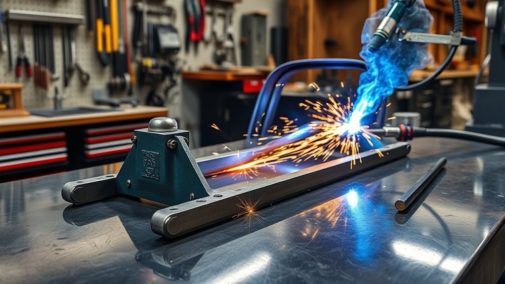
To build a welding jig for auto body work, start with a clear repair plan, accurate reference points, a safe hot-work area, and a rigid frame that holds the panel, bracket, or fabricated part in the same position every time. A useful jig supports the work without forcing it, leaves room for the torch and grinder, limits heat movement, and makes final fit-up easier before the part is installed.
Quick Answer
Build an auto body welding jig from a flat base, rigid tubing or angle iron, fixed locating stops, and adjustable clamps. Mark the part’s centerline and mounting points, tack the frame, verify its sides, corners, diagonals, and flatness, then finish-weld in short passes. Test the first completed part before relying on the jig.
Key Takeaways
- Use a shop-made jig for detached panels, brackets, tabs, and other suitable fabrication—not as a substitute for an OEM-approved frame bench or collision measuring system.
- Identify the part, material, reference dimensions, and approved joining process before designing a jig for vehicle repair.
- Locate the part against solid stops before tightening clamps, and never use clamp pressure to hide a poor fit.
- Tack the jig first, check its sides, corners, diagonals, and flatness, then finish-weld in short, balanced passes.
- Release and remeasure the first welded part before using the fixture for repeated production.
- Follow vehicle-maker procedures for structural materials, welding methods, electronics, high-voltage systems, corrosion protection, scanning, and calibration.
At a Glance
| Time Required | About 2 to 6 hours for a small panel or bracket jig; more for adjustable or repeated-use fixtures |
| Difficulty | Intermediate because layout, clamp pressure, weld sequence, and verification affect accuracy |
| Tools Needed | Welder, grinder, drill, clamps, square, tape measure, angle finder, straightedge, marker, PPE, ventilation, and fire extinguisher |
| Cost | Roughly $30 to $150 for a small jig when major tools are already owned; repair-data access and specialized collision equipment cost extra |
Understanding the Purpose of a Welding Jig

A welding jig is a fixture that locates and holds auto body parts while you tack, weld, test-fit, and inspect them. It can keep brackets, patch panels, tabs, mounting plates, and replacement pieces from shifting as heat moves through the metal.
A small shop-made jig is most useful when you need repeatable placement. You may need to hold matching brackets at the same angle, support a detached panel while adding tabs, or keep a fabricated patch flat while you drill and weld mounting points.
A jig is not the same as a collision frame bench. A frame bench or vehicle-specific measuring system supports structural repairs at factory reference points. A small fabrication jig usually holds a detached component or a limited nonstructural assembly. Do not use a homemade fixture to guess structural dimensions or pull a damaged vehicle into alignment.
The best jig performs three jobs at once:
- It supports the part without bending or twisting it.
- It locates the part against fixed reference surfaces or stops.
- It leaves enough access to weld, inspect, measure, grind, and remove the finished part.
A welding jig does not create accuracy. It preserves the accuracy built into the measurements, locating stops, contact surfaces, and clamp points.
One advantage of a shop-built fixture is its jig customization. You can adapt it to one panel, bracket, repair area, or repeated assembly. In a tight workspace, modular mini fixture tables can improve workflow because stops, clamps, and support blocks can be moved as the job changes.
Know When a DIY Jig Is Appropriate
A shop-made jig is a practical choice for light fabrication, detached patch panels, brackets, tabs, small assemblies, bumper accessories, and repeatable nonstructural positioning. It is not a substitute for a professional frame bench, vehicle-specific measuring equipment, or an OEM structural repair procedure.
Warning: Do not guess on frame rails, pillars, rockers, suspension mounting points, battery enclosures, restraint-system mounts, or crash-management parts. Use the vehicle maker’s repair information and qualified collision-repair equipment. For commercial motor vehicles, frame attachments and welded frame repairs must follow manufacturer recommendations under 49 CFR 393.201.
Stop and obtain professional help when:
- The repair affects a structural load path or occupant-protection component.
- The original dimensions cannot be confirmed from an undamaged part or approved repair data.
- The part contains ultra-high-strength steel, cast aluminum, carbon fiber, magnesium, or another material you cannot identify.
- The repair is close to an airbag, seat-belt pretensioner, fuel system, refrigerant line, high-voltage cable, or traction battery.
- The vehicle maker prohibits straightening, heating, sectioning, or the welding process you planned to use.
- A scan, calibration, weld test, or specialized joining tool is required and unavailable.
Verify the Part, Material, and Repair Method First
Before cutting jig material, decide whether you are fabricating a detached part or repairing the vehicle itself. That decision controls the measurements, joining process, safety setup, and final inspection.
For vehicle repair, look up the model-specific body repair information. Confirm:
- The vehicle year, model, body style, and relevant equipment.
- Whether the part is structural or nonstructural.
- The material and strength classification of each layer.
- The approved sectioning or replacement location.
- The required weld, spot weld, MIG-brazed joint, rivet, adhesive, or weld-bonded connection.
- The factory measuring points and allowable dimensions.
- Required corrosion-protection materials and application areas.
- Pre-repair scans, post-repair scans, inspections, or ADAS calibrations.
The I-CAR OEM Technical Information Matrix can help locate manufacturer resources, but the vehicle maker’s current repair procedure remains the controlling source.
Note: Building a fixture from an undamaged opposite-side part is useful only when the parts are true mirror images. Confirm handed brackets, offsets, hole sizes, reinforcement layers, and model-specific changes before copying dimensions.
Choosing Materials for Your Welding Jig Assembly
Choose jig material by considering the part’s weight, the unsupported span, clamp force, expected heat, required accuracy, and how often the fixture will be used. The frame must be stiff enough to keep its reference points stable but manageable enough to move, store, and inspect.
Products Worth Considering

Item Package Dimension: 88.99L x 1.24W x 0.99H inches


Material Strength Considerations
Square or rectangular mild-steel tubing is a common base material for small and medium fixtures because it is straight, easy to cut, and stiff for its weight. Add crossbars or gussets where the fixture spans a long distance or where a clamp creates a concentrated load.
Use angle iron for ledges, straight locating edges, and mounting rails. Use flat bar or plate for tabs, slotted brackets, bolt-on stops, and removable clamp arms. Precision-cut tabs can improve repeatability, but accurately drilled and deburred flat bar can also work.
Avoid choosing tubing solely because it is easy to cut. Thin material may flex when the clamps are tightened, while oversized material can make a simple jig needlessly heavy. Clamp a sample load to the proposed frame and check for movement before completing the fixture.
Weight Reduction Techniques
Boxed tubing resists bending efficiently and can reduce weight compared with oversized solid bar. Place material where it carries a load: under locating points, below clamps, across open spans, and near upright supports.
Use relief cuts only when they provide necessary clearance for a clamp, tool, fastener, shielding-gas hose, or removable part. Round or smooth sharp inside corners and avoid removing enough material to let the fixture twist.
Warning: Never describe a cutout as clearance for a vehicle “gas line” without identifying the system. Fuel, brake, refrigerant, washer, restraint, and high-voltage lines must be located, protected, or removed according to the vehicle maker’s procedure before hot work begins.
Connection Point Accuracy
Connection-point accuracy matters more than the appearance of the jig. A smooth weld bead cannot correct a misplaced stop or an inaccurate bolt pattern.
Before cutting metal, mark:
- The part or vehicle centerline.
- Primary support surfaces.
- Bolt holes, plug-weld holes, studs, or mounting points.
- Panel edges, body lines, and planned gaps.
- Bracket angles and height references.
- Clamp positions and stop-block locations.
- Clearance for the torch, nozzle, grinder, drill, helmet, gloves, and welding leads.
- The direction in which the completed part must leave the fixture.
Locate Before You Clamp
Support and locate the part before applying clamp pressure. The part should rest naturally against the stops. Clamps should keep it seated, not pull it several millimeters or degrees into position.
Use broad pads, shaped blocks, copper or aluminum backing where suitable, or replaceable contact faces to avoid denting thin panels. Do not place a hard clamp foot on a visible body line unless the contact surface is designed to match it.
Too many locating points can make a fixture difficult to load and may force a slightly varied part out of shape. Use only the stops needed to control position, then add clamps that press the part toward those stops.
Pro Tip: Mark the jig with a paint pen before final welding. Label “front,” “left,” “right,” “centerline,” clamp numbers, part number, and “do not clamp” areas. Add witness marks across adjustable joints so unwanted movement is easy to spot.
Safety Setup Before Cutting or Welding
Building and using a jig are hot-work operations. Prepare the work area before cutting, grinding, or striking an arc.
- Move paper, cardboard, rags, solvents, aerosols, fuel containers, and other combustibles away from the area.
- Inspect openings, wall cavities, floor cracks, the opposite side of panels, and spaces below the work where sparks may travel.
- Use welding blankets or noncombustible guards to contain sparks without trapping fumes.
- Keep a suitable fire extinguisher ready and make sure the operator knows how to use it.
- Wear safety glasses with side protection under a welding helmet, plus welding gloves, suitable clothing, and hearing protection.
- Protect nearby workers and bystanders from arc radiation and flying particles.
- Route welding leads, air hoses, extraction hoses, and cords away from walkways and hot metal.
- Use local exhaust ventilation or effective fume control, especially for coated, galvanized, oily, or unknown metal.
- Remove paint, undercoating, adhesive, seam sealer, plating, and contamination from the weld zone using a method appropriate for the material.
- Do not weld a container, tube, cavity, or component that may hold fuel, refrigerant, vapors, pressure, or an unknown substance.
OSHA’s welding standard requires fire-prevention measures, suitable eye protection, and ventilation under specified workplace conditions. It also requires a fire watch when listed hazards are present, including certain combustible exposures within 35 feet, and requires that watch to continue for at least 30 minutes after welding or cutting. A home shop should use equally conservative fire precautions even when workplace rules do not directly apply.
NIOSH explains that welding fumes contain metals and that exposure varies with the wire, rod, flux, base metal, coating, and work area. Keep your head out of the fume plume and capture fumes close to the source when possible.
For a related preparation guide, see these basic welding safety gear and setup tips.
Warning: Welding on a hybrid or electric vehicle can expose you to lethal voltage and battery-fire hazards. Follow the exact vehicle-maker shutdown procedure. High-voltage de-energization, verification, removal, and storage may be restricted to trained or certified technicians. Do not work near a damaged traction battery or orange high-voltage cable.
Essential Tools and Supplies
You do not need a large fixture table for every jig, but you do need reliable measuring tools, stable supports, and enough clamps to hold the part without forcing it.
- Welding machine suitable for the jig material
- Angle grinder with approved cutting, grinding, and flap discs
- Drill, step bit, hole saw, or drill press for holes and slots
- Tape measure, steel rule, machinist or framing square, angle finder, and level
- Straightedge, feeler gauges, spacer blocks, or setup shims
- C-clamps, locking pliers, panel clamps, magnets, or toggle clamps
- Square tubing, rectangular tubing, angle iron, flat bar, tabs, plate, and gussets
- Bolts, washers, locknuts, threaded inserts, and spacer sleeves for adjustable stops
- Marker, scribe, center punch, paint pen, and labels
- Same-material scrap for test settings when welding a vehicle repair part
- PPE, welding screens, ventilation or extraction, and a suitable fire extinguisher
If you have access to a CNC plasma cutter, it can produce repeatable tabs, flanges, and mounting plates. If not, drill and shape flat bar carefully, then deburr every edge and hole so the hardware seats flat.
Products Worth Considering

POWERFUL HOLDING FORCE: Featuring robust magnets embedded in the welding holder, these durable magnets boasts a strong magnetic holding force of up to 25/50 lbs, ensuring reliable performance.


Two-Magnet Combo Pack: Includes one MLD300 (3 in. H x 2 in. W x 0.6 in. thick, 20 lb pull force) and one MLD500 (5 in. H x 3.4 in. W x 0.7 in. thick, 33 lb pull force). Set weight is 1.0 lb.
Step-by-Step Guide to Assembling Your Welding Jig
Build the jig from confirmed measurements rather than visual estimates. A dependable fixture should locate the part without stress, provide safe tool access, and remain stable after its own welds cool.
Step 1: Define the Job and Reference Points
Decide exactly what the fixture must hold and what it must not do. A detached patch-panel jig, bracket fixture, bumper-tab jig, and structural measuring system have different requirements.
Use an original undamaged part, a verified opposite-side part, a rigid template, manufacturer measuring data, or a combination of these references. Record the centerline, bolt spacing, height, angle, panel gap, and any orientation that affects fit.
For vehicle repair, confirm the material and approved attachment method before designing around a torch or clamp that may not be allowed by the repair procedure.
Step 2: Sketch the Jig Before Cutting
Draw the base, crossbars, support points, locating stops, clamp directions, adjustment slots, and clearance zones. The sketch only needs to be clear enough to prevent layout mistakes.
Plan how the torch, spot-welder arms, drill, rivet tool, or grinder will reach the joint. Also plan how the completed part will be removed. A closed stop or crossbar can trap a part after welding shrinkage occurs.
Step 3: Cut and Prepare the Frame Material
Cut the tubing, angle iron, and flat bar to length. Deburr the cuts and check that each base piece sits flat without rocking. Clean the intended weld areas to bare, uncontaminated metal.
When using galvanized, painted, undercoated, or plated material, identify the coating, remove it from the weld zone using a safe method, and control the fumes. For more preparation information, see this guide to welding preparation for galvanized steel.
Step 4: Build the Base Flat and Square
Lay the base on the flattest rigid surface available. A fixture table is ideal, but a verified flat steel plate or heavy bench can work for a small jig.
Clamp the pieces lightly and check:
- Both intended length measurements
- Both intended width measurements
- Each corner with a reliable square
- Both diagonal measurements
- Flatness with a straightedge or known-flat surface
Matching diagonals are one useful check, but they do not replace checking side lengths, corner angles, and flatness. Tack the corners only after all measurements agree with the drawing.
Add small tacks first. Let them cool, release unnecessary setup pressure, and measure again before adding more weld.
Step 5: Add Crossbars, Stops, and Clamp Points
Add crossbars where they prevent twisting or support a locating point. Then install stop blocks, pins, tabs, or shaped supports where the part must sit.
Use bolts, threaded blocks, shims, or slotted tabs when adjustment is useful. Protect adjustable threads from weld spatter and avoid placing a slot where clamp force can make it slip.
Do not rely on clamps alone for location. Stops establish position; clamps keep the part seated against those stops.
Step 6: Test-Fit the Part and Verify the First Piece
Place the unwelded part in the jig and check every contact point. It should sit naturally without heavy clamp pressure. If a clamp must pull the part into place, find the measurement or stop that is wrong.
Check bolt holes, panel edges, bracket angles, body lines, gaps, tool access, and removal clearance. Confirm that the clamps do not cover the weld, block shielding gas, or dent a finished surface.
After the first part is welded:
- Allow it to cool naturally.
- Release every clamp.
- Remove the part without prying against a locating surface.
- Remeasure the part while it is free of the fixture.
- Test-fit it in its final location.
- Correct the fixture before producing another part if the first one moved.
Pro Tip: A jig can hide springback while the clamps are tight. The first part is not proven until it has cooled, been unclamped, remeasured, and test-fitted outside the fixture.
Step 7: Finish-Weld in Short, Balanced Passes
Once the fixture is tacked and verified, weld the frame in short sections. Move between separated areas rather than completing one long side at once. Recheck the fixture as heat builds.
The best sequence depends on the frame shape, joint placement, and stiffness, so treat “alternating sides” as a starting method rather than a guarantee. Stop if a measurement begins to change.
Let the fixture cool naturally. Do not quench one area with water unless a qualified procedure specifically calls for it, because uneven cooling can change the frame’s shape or material condition.
Step 8: Verify, Label, and Store the Jig
After cooling, recheck the base dimensions, corner angles, diagonals, centerline, bolt spacing, stop locations, and flatness. Grind only what is needed for safe handling, part clearance, or removal of harmful spatter.
Label the jig with the part name or number, vehicle application when relevant, revision date, orientation, clamp sequence, and any required spacer or shim size. Store it flat or support it at strong frame points so storage does not bend it.
Tips for Clearance and Access
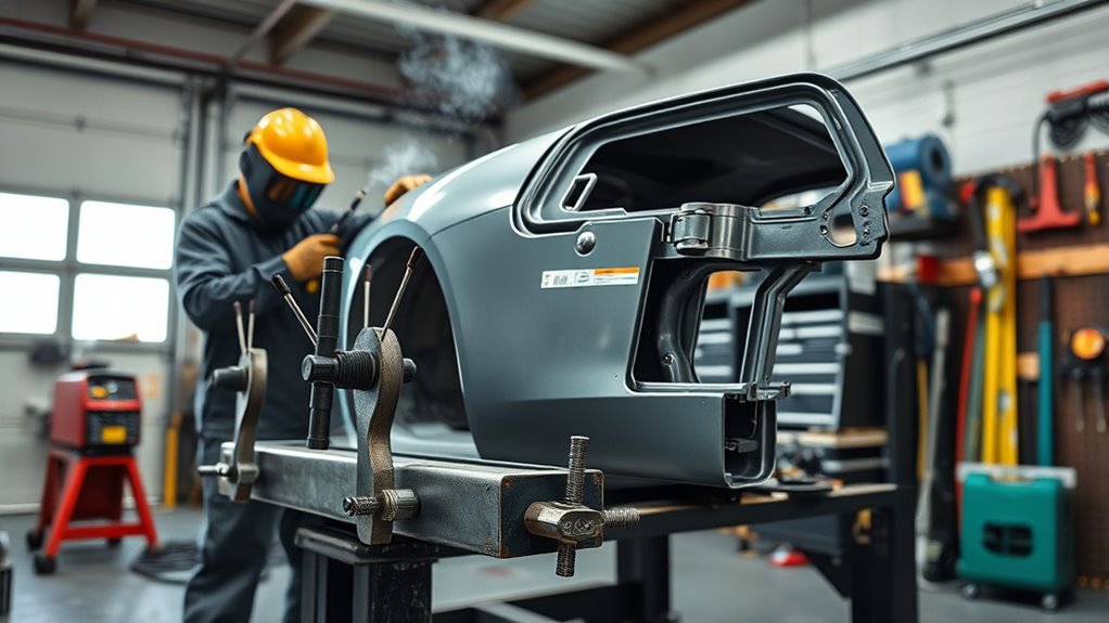
Define clearance zones around panel edges, bolt holes, weld seams, underbody obstructions, and every tool that must enter the fixture.
Design for access from more than one angle. You may need to reach tack welds, plug welds, seam welds, rivets, adhesive squeeze-out, or inspection points without removing the part. Leave room for cleaning and finishing tools as well as the welding torch.
A flat fixture usually provides the best stability, but a vertical or angled fixture may give better access to a tall bracket or curved panel. Removable legs or bolt-on supports can provide both positions without building two fixtures.
Relief cuts can clear a clamp body, fastener, shielding-gas hose, or grinder. Keep the cuts smooth, avoid sharp internal corners, and reinforce the area if the cut weakens a loaded section.
Note: Check access with the actual torch nozzle, clamp, welding helmet, gloves, drill, and grinder. A gap that looks adequate on an empty bench may be unusable once the part, cables, extraction hose, and PPE are in place.
Using the Jig on Auto Body Parts
Use the completed jig as a controlled locating tool, not as a way to force damaged metal back into shape. Repair or replace a distorted part before placing it in a fixture intended to reproduce an undamaged part.
Detached Panels, Brackets, and Tabs
For thin panel work, place spaced tacks around the part before making longer welds. Use the lowest appropriate heat input, move between separated areas, and allow time for cooling. A rigid fixture helps control movement but cannot eliminate sheet-metal shrinkage.
For brackets and tabs, use fixed stops to control angle, height, and spacing. Tack the part while it is fully located, then release enough clamps to confirm it is not being held in a strained position. Finish-weld only after the tacked assembly remains stable.
When the final installation uses bolts, install temporary bolts or accurate locating pins in the jig. A clamp touching the edge of a drilled hole is less repeatable than a pin or fastener centered in that hole.
Vehicle-Mounted Hot Work
Before welding on a vehicle, inspect both sides of the repair and trace nearby wiring, fuel lines, brake lines, refrigerant pipes, washer hoses, insulation, seam sealer, foam, sound deadener, trim, glass, airbags, pretensioners, sensors, and electronic modules.
Follow the current vehicle-maker procedure for:
- Disconnecting and isolating the 12-volt battery or batteries
- Waiting the specified time for the restraint system to discharge
- Disabling or protecting SRS components
- De-energizing a hybrid or electric high-voltage system
- Removing a traction battery or electronic module when required
- Locating the welding return clamp close to the weld on the correct panel or assembly
- Routing welding cables away from modules, sensors, and vehicle wiring
- Protecting glass, paint, trim, and hidden cavities from heat and sparks
I-CAR’s welding precautions address battery isolation, restraint-system procedures, the welding-current path, nearby electronics, and high-voltage systems. Manufacturer instructions can be more restrictive and always take priority.
Restore Corrosion Protection and Check Vehicle Systems
Welding, drilling, and grinding can remove factory coatings from both visible and hidden surfaces. After the repair passes inspection, restore every affected layer specified by the manufacturer. Depending on the vehicle and joint, this may include:
- Approved weld-through or direct-to-metal primer
- Structural adhesive or weld-bonding adhesive
- Seam sealer
- Paint and underbody coating
- Cavity wax or internal corrosion protection
- Replaced foam, plugs, shields, and insulation
Do not seal a joint until the welds, dimensions, and fit have been inspected. Keep primers and coatings out of electrical ground contacts and any area the repair procedure says must remain bare.
If the repair affects cameras, radar units, parking sensors, steering components, ride height, wheel alignment, or mounting points, follow the manufacturer’s scan and calibration procedures. NHTSA explains how driver-assistance technologies depend on cameras and other sensors, while the vehicle maker determines the repair and calibration requirements for a specific model.
Troubleshooting Common Welding Jig Challenges
Most jig problems come from inaccurate reference points, weak support, excessive clamp force, blocked access, fixture wear, or uncontrolled heat.
| Problem | Likely Cause | Fix |
| Part does not fit after welding | Jig moved, reference dimensions were wrong, or the part shrank | Recheck the source measurements, fixture geometry, first-piece dimensions, and weld sequence |
| Part changes shape when unclamped | The clamps forced poor fit-up or hid weld shrinkage | Correct the locating stops, reduce clamp force, improve fit-up, and recheck the free part after cooling |
| Panel warps | Too much heat, long welds, poor fit-up, or inadequate support | Use spaced tacks, suitable settings, shorter welds, more cooling time, and supports close to the joint |
| Clamp blocks the weld | Clamp direction or removal sequence was not planned | Move the stop, add a removable tab, or use a lower-profile clamp that still presses toward the locator |
| Bolt holes do not line up | Hole centers were measured from an unreliable edge | Use centerlines, accurate pins, transfer punches, templates, and independent cross-checks |
| Jig flexes when clamped | Frame is too light, the clamp load is unsupported, or a slot slips | Add a crossbar or gusset, shorten the unsupported span, or move the clamp over a stronger section |
| Part is difficult to remove | Stops trap the part or weld shrinkage closes the removal path | Use removable stops, tapered locating pins, or a planned removal direction with adequate clearance |
| Later parts differ from the first part | Spatter, worn stops, loose bolts, damaged threads, or fixture distortion | Clean locating faces, tighten hardware, replace worn contacts, and verify the fixture against a known part |
Use relief cuts only when necessary for tool, fastener, clamp, or shielding-gas access. If you use drilled flat bar instead of precision-cut tabs, deburr the holes and verify that the fasteners seat flat.
Always use cutting and grinding accessories approved for the tool and speed. For related hazards and personal protection, review these angle grinder safety considerations before shaping jig material.
Choose the Correct Welding Process and Control Heat
The correct process depends on whether you are welding the fixture, fabricating a detached part, or joining a replacement component to a vehicle.
GMAW, commonly called MIG welding, is practical for many mild-steel jig frames, brackets, tabs, and suitable nonstructural panels. It is not automatically approved for every modern vehicle structure.
GTAW, commonly called TIG welding, can provide precise heat and filler control on suitable thin steel, stainless steel, and aluminum. It requires clean fit-up, suitable equipment, and more operator skill.
Stick welding is useful for many heavier fabrication jobs but is usually difficult to control on thin body sheet metal. It is rarely the first choice for a light panel jig or cosmetic sheet-metal repair.
Modern collision repairs may call for squeeze-type resistance spot welding, GMA plug welds, MIG brazing, weld bonding, riveting, adhesives, or combinations of these methods. Use the process, wire, electrode, adhesive, weld spacing, hole size, and test method identified by the manufacturer.
Make Test Welds Before Welding the Vehicle
Use scrap that matches the repair material, thickness, layer count, coating preparation, joint design, orientation, wire, and shielding gas as closely as possible. Adjust the equipment and technique on the scrap rather than on the vehicle.
Some vehicle makers require a passing destructive test for each unique joint or welding setup. Follow the exact test method and acceptance criteria in the body repair information. Do not substitute a visual bead inspection when the procedure requires a peel, twist, chisel, or nugget test.
Heat management still matters when the approved process is known. Use clean fit-up, suitable settings, the required weld spacing, and time between welds. Avoid adding extra weld length “for strength,” because more heat can increase distortion or damage protected material.
Proper ventilation and a stable work surface make test setup, measurement, and repeated welding safer and more consistent.
Maintaining and Rechecking a Reusable Jig
A repeated-use fixture can slowly lose accuracy. Heat, drops, storage loads, clamp pressure, loose hardware, grinding, and weld spatter can all change a locating surface.
Before each use:
- Clean spatter and debris from every locating face.
- Check bolts, pins, threaded inserts, slots, and toggle clamps.
- Inspect tubing and welds for cracks, dents, or bending.
- Confirm adjustable stops still align with their witness marks.
- Check critical dimensions against the drawing, template, or a known-good part.
- Replace worn pins, bushings, pads, and sacrificial tabs.
Do not grind a stop to make one incorrect part fit. Identify whether the error is in the new part, the source measurement, the jig, or the welding process before changing a reference surface.
Frequently Asked Questions
What is the best type of welder for auto body work?
For suitable detached mild-steel brackets, tabs, jigs, and nonstructural panels, a properly set GMAW or MIG welder is often practical. TIG can provide more control for suitable thin metal and aluminum. Structural collision repairs may instead require spot welding, MIG brazing, weld bonding, riveting, or another vehicle-maker-approved process.
How do you make a jig and fixture?
Measure the part, mark its centerline and mounting points, and build a flat base from tubing or angle iron. Add supports, fixed locating stops, and clamps that press the part toward those stops. Tack the fixture, check its sides, corners, diagonals, and flatness, then finish-weld in short, balanced passes.
Is it illegal to weld a vehicle frame?
There is no single rule covering every passenger vehicle and location. Inspection laws, manufacturer restrictions, insurance requirements, and repair type all matter. For commercial motor vehicles, federal rules require welded frame repairs to follow manufacturer recommendations. Structural frame or unibody work should use current OEM repair information and qualified collision-repair equipment.
What is the golden rule in welding?
Preparation is the most useful rule: identify the material, clean it, make the correct joint, verify fit-up, use the approved process, protect yourself, and test the setup before welding the finished part. Good technique cannot fully correct contamination, poor access, or forced alignment.
Can I build an auto body welding jig without a fixture table?
Yes, for a small fixture. Use the flattest rigid surface available, support the base near its corners and crossbars, and measure frequently. A fixture table speeds setup, but careful layout, stable clamping, and repeated flatness checks can still produce an accurate small jig.
How do I keep a welding jig from warping?
Use accurate fit-up, tack the complete frame before finish welding, add needed crossbars or gussets, and weld short sections in a balanced sequence. Stop to measure as the work heats, allow natural cooling, and verify the fixture again after all clamps are released.
How tight should the clamps be on a welding jig?
Use only enough pressure to keep the part seated against its locating stops. If the clamp must bend, twist, or pull the part into position, correct the fit or the fixture. Thin visible panels may need broad or shaped pads to prevent dents.
Can a homemade jig be used for structural vehicle alignment?
A homemade fabrication jig should not replace an OEM-approved frame bench, dedicated fixture set, or electronic measuring system. Structural alignment depends on verified factory reference points, anchoring, pulling procedures, material limits, and measurements that a simple shop jig may not provide.
Conclusion
Building a welding jig for auto body work is an exercise in controlled measurement. Start with a verified part or repair plan, support the work without forcing it, locate it against solid stops, and use clamps only to keep those references seated. Tack and measure before finish welding, then prove the fixture by cooling, unclamping, measuring, and test-fitting the first completed part.
For work on a vehicle, the fixture is only one part of the repair. The material, joining method, electrical shutdown, high-voltage precautions, corrosion protection, scanning, and calibration must follow current vehicle-maker information. A simple jig can become one of the most useful tools in an auto body workflow, but only when its limits are understood and its reference points remain accurate.
Sources
- OSHA 1910.252 Welding, Cutting, and Brazing — supports fire prevention, fire-watch, eye protection, PPE, coating, and ventilation guidance.
- OSHA 1910.133 Eye and Face Protection — supports primary eye protection and appropriate face-protection requirements.
- CDC/NIOSH Welding Fumes and Manganese — supports welding-fume and metal-exposure cautions.
- 49 CFR 393.201 Frames — supports manufacturer-recommendation requirements for commercial motor-vehicle frame welding.
- NHTSA Driver Assistance Technologies — supports the explanation of camera- and sensor-based vehicle safety systems.
- I-CAR Battery and Electronics Precautions During Welding — supports battery isolation, current-path, restraint-system, electronics, and high-voltage precautions.




