Running out of shielding gas halfway through a weld is every welder’s headache. One second the bead is smooth; the next it is spattering or showing porosity. Whether you are welding mild steel, stainless steel, or aluminum, knowing how to calculate MIG welding gas consumption helps you plan cylinder changes, control costs, and maintain reliable shielding.
The formal process name is gas metal arc welding, or GMAW, although most shops call it MIG welding. The calculation is simple once you know the flow rate and the total time gas is actually flowing. This guide explains the formula, how to measure gas-on time, how to estimate cylinder life, and where real-world gas losses enter the calculation.

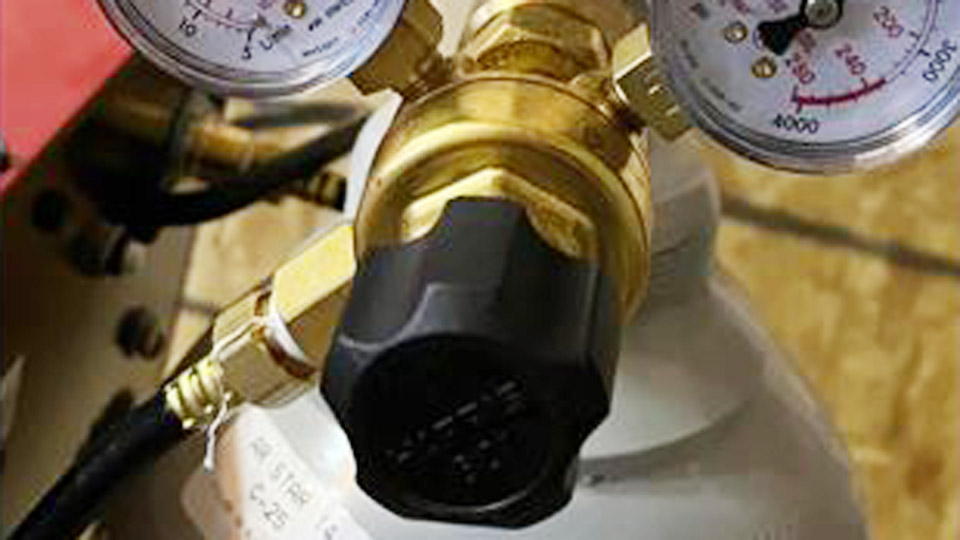
Photo credit: WestAir Gases
Quick Answer
Multiply the shielding-gas flow rate by the total gas-on time. In U.S. units, gas used in cubic feet equals CFH multiplied by gas-on minutes, divided by 60. In metric units, liters used equals L/min multiplied by gas-on minutes. Add purging, preflow, postflow, trigger surges, and a practical cylinder reserve.
Key Takeaways
- Use gas-on time, not total job time and not arc time alone.
- Set and read the flowmeter while gas is moving through the gun.
- Follow the welder manual, filler-wire data sheet, or welding procedure instead of treating one CFH setting as universal.
- Do not expect the full nominal cylinder capacity to be available for production work.
- Control drafts and repair leaks before increasing the flow rate.
At a Glance
| Time Required | About 5–10 minutes for a basic estimate; longer if you time a complete production cycle |
| Difficulty | Easy |
| Tools Needed | Flowmeter or flow-gauge regulator, stopwatch or cycle timer, calculator, cylinder-capacity label, and approved leak-detection solution |
| Cost | No added cost if your regulator includes a flowmeter; a nozzle flow checker is optional |
Why Calculating MIG Welding Gas Consumption Matters
Shielding gas protects the molten weld pool from the surrounding atmosphere. If coverage is lost, nitrogen, oxygen, moisture, and other contaminants can contribute to porosity, unstable arc behavior, poor bead appearance, and unacceptable weld quality.
Calculating consumption also prevents avoidable downtime. When you know approximately how many cubic feet or liters a job will require, you can select a suitable cylinder, schedule refills, and avoid starting a critical weld with too little gas remaining.
Gas use is also a direct operating cost. A single hobby machine may not consume much, but unnecessary flow, leaks, purging, and repeated trigger starts add up across a production line. Lincoln Electric notes that gas surges can occur when the torch solenoid opens, making frequent starts another source of waste.
Gas used in cubic feet = flow rate in CFH × gas-on minutes ÷ 60.
Understanding Shielding Gas, Flow, and Pressure
GMAW uses a continuously fed wire electrode and an external gas shield. Although “MIG” originally referred to metal inert gas welding, many common GMAW applications use active gases, including carbon dioxide, or mixtures containing CO₂.
The shielding gas passes through the regulator, hose, machine gas valve, gun, diffuser, and nozzle. The nozzle spreads the gas around the arc and molten weld pool. Restricted passages, damaged seals, poor gun seating, or a nozzle packed with spatter can reduce the gas that reaches the weld even when the regulator appears correctly set.
Flow Rate Is Not the Same as Pressure
Flow rate describes how much gas moves through the system over time. It is normally shown as cubic feet per hour (CFH) or liters per minute (L/min).
Pressure describes force per unit area and is commonly shown in pounds per square inch (PSI). A cylinder-pressure gauge does not tell you the gas flow at the nozzle. Use the flow scale on a suitable regulator or flowmeter, and make the adjustment while gas is flowing.
Note: Cylinder size labels such as 40, 80, or 125 cubic feet are nominal capacities. Sizes and fill practices can vary by supplier, and a pressure reading is not a precise substitute for the cylinder’s stated capacity.
Common Shielding Gases and Their Uses
| Material and Process | Common Gas Options | Important Notes |
|---|---|---|
| Mild steel, short-circuit GMAW | 75% argon/25% CO₂ or 100% CO₂ | C25 generally provides a smoother arc and less spatter. Straight CO₂ is economical and can provide deeper penetration but often produces more spatter. |
| Stainless steel, short-circuit GMAW | Machine- and wire-specific blends, including helium-rich tri-mix or low-CO₂ argon blends | A traditional recommendation is 90% helium/7.5% argon/2.5% CO₂, but some newer machines are programmed for blends such as 98% argon/2% CO₂. |
| Aluminum GMAW | 100% argon; argon/helium blends for selected procedures | Miller identifies 100% argon as the common choice and recommends avoiding CO₂ contamination in aluminum GMAW. |
Always confirm the gas with the filler-wire data sheet, machine program, welding procedure specification, and applicable code. A gas that works with one transfer mode or wire may not be suitable for another.
How to Calculate Gas Consumption in MIG Welding
The most accurate shop calculation uses the flow rate and the total time the gas valve is open. For a basic machine without adjustable preflow or postflow, gas-on time may be close to trigger time. On other equipment, it can include programmed preflow, postflow, purging, test flow, and time when the trigger is held without an arc.
Products Worth Considering

Professional Ggs Flow Tester / Meter Peashooter Style

WIDE APPLICATION: It easily connects to Argon, Helium, and Argon/CO₂ mixed gas tanks via the CGA-580 inlet nut. No additional adapters are required. Featuring superior airtight and leak-proof performance, it achieves stable and sealed gas supply with minimal gas loss. This regulator is ideal for MIG/TIG welding, chemical processing, general industrial use, and electronics industry applications.

Brand New BETOOLL Argon / CO2 regulator and flow meter.
Step 1: Record the Gas and Cylinder Capacity
Read the cylinder label or supplier documentation and record:
- Gas or gas-mixture name
- Nominal cylinder capacity in cubic feet or liters
- Refill or exchange cost, if you want a cost estimate
- The reserve you intend to keep before changing the cylinder
Do not assume every cylinder with similar dimensions contains the same amount of gas.
Step 2: Set and Verify the Flow Rate
Open the cylinder valve according to the regulator and machine instructions. Use the machine’s purge or gas-check mode when available. Otherwise, follow the manufacturer’s procedure for checking flow without creating an unintended arc.
Warning: Pulling the MIG-gun trigger may energize the wire and start wire feed. Point the gun in a safe direction and use the approved purge mode or manufacturer procedure. Do not improvise electrical disconnections unless the manual specifically permits them.
Adjust the flow while gas is moving through the entire system. A floating-ball flowmeter must normally be read at the specified point on the ball, as directed by its manufacturer. Keep the meter upright if its design requires an upright position.
For a second check, a nozzle flow tester can measure the gas that actually reaches the gun outlet. A large difference between regulator flow and nozzle flow can indicate a leak, blockage, damaged O-ring, loose gun connection, or restricted diffuser.
Step 3: Measure Gas-On Time
Do not automatically use the total job duration. A six-hour fabrication job may contain setup, fit-up, grinding, inspection, and repositioning. It may also contain hundreds of starts that consume more gas than a few long welds.
Measure gas-on time with one of these methods:
- Stopwatch method: Start the timer whenever the gas valve opens and stop it when flow ends.
- Cycle method: Time one complete repeated cycle, including preflow and postflow, then multiply by the number of cycles.
- Machine-data method: Use logged gas-valve or process time when the welding system provides reliable production data.
- Cylinder-use method: Record actual cylinder consumption over several comparable jobs and use the measured average for future planning.
Step 4: Apply the Correct Formula
U.S. formula:
Gas used in cubic feet = CFH × gas-on minutes ÷ 60
Example:
- Flow rate: 20 CFH
- Gas-on time: 18 minutes
- Gas used: 20 × 18 ÷ 60 = 6 cubic feet
Metric formula:
Gas used in liters = L/min × gas-on minutes
Example:
- Flow rate: 10 L/min
- Gas-on time: 18 minutes
- Gas used: 10 × 18 = 180 liters
For conversion, 1 CFH is approximately 0.472 L/min.
Step 5: Estimate Cylinder Runtime
For a simple theoretical runtime:
Theoretical runtime in hours = nominal cylinder capacity in cubic feet ÷ flow rate in CFH
An 80-cubic-foot cylinder at 20 CFH has a theoretical continuous gas-flow time of:
80 ÷ 20 = 4 hours
Actual usable time will be lower when the job includes purging, gas surges, leakage, pressure left in the cylinder, or a planned reserve.
For practical planning:
Planned runtime = usable cylinder capacity ÷ flow rate
If you choose to keep a 5-cubic-foot planning reserve in a nominal 40-cubic-foot cylinder, the planned usable capacity is 35 cubic feet. At 20 CFH, that equals 1.75 hours of planned gas-on time. The reserve in this example is a shop-planning choice, not an industry standard.
Step 6: Estimate Complete Jobs
Divide planned usable capacity by gas consumption per job:
Complete jobs per cylinder = usable cylinder capacity ÷ gas used per job
Using the earlier 6-cubic-foot job and 35 cubic feet of planned usable capacity:
35 ÷ 6 = 5.83
That means you should plan for five complete jobs, with some gas remaining. Do not schedule a sixth complete job based on the decimal alone.
Step 7: Calculate Gas Cost per Job
A rough gas-only cost calculation is:
Gas cost per job = gas used per job ÷ nominal cylinder capacity × refill price
If a 40-cubic-foot refill costs $60 and a job theoretically uses 6 cubic feet:
6 ÷ 40 × $60 = $9 in cylinder gas
This estimate does not include cylinder rental, delivery, environmental charges, downtime, or losses beyond the measured gas-on time.
Production Formula for Multiple Welding Stations
For several identical welding stations:
Total gas used = flow rate × gas-on hours per station × number of stations
For example, four stations operating at 30 CFH for 2.5 gas-on hours each would theoretically use:
30 × 2.5 × 4 = 300 cubic feet
If stations use different flow rates or cycle times, calculate each station separately and add the totals.
Quick Reference Table for Gas Consumption
| Application | Common Gas | General Starting Guidance | Theoretical Use for 1 Gas-On Hour |
|---|---|---|---|
| Mild-steel short circuit | C25 or CO₂ | Common equipment guidance falls within roughly 20–35 CFH; verify the exact machine and wire instructions | 20–35 cubic feet |
| Stainless short circuit | Approved tri-mix or machine-specific low-CO₂ blend | Use the machine program, wire data, or WPS; do not assume one universal blend or flow | Equal to the selected CFH setting for one gas-on hour |
| Aluminum GMAW | 100% argon | Miller lists 20–30 CFH as a recommended range for its general aluminum guidance | 20–30 cubic feet |
These are starting references, not qualified welding procedures. Nozzle size, gas composition, transfer mode, current, joint position, gun design, and local airflow can all change the required flow.
Common Calculation Mistakes to Avoid
- Reading the meter with no gas flowing: The setting may change once the gun valve opens.
- Confusing PSI with CFH: Pressure and flow are different measurements.
- Using total job time: Count gas-on time, not lunch, setup, grinding, or inspection time.
- Counting arc time only: Include preflow, postflow, purging, test flow, and non-arcing trigger time.
- Assuming the full cylinder capacity is available: Keep a practical reserve and account for process losses.
- Rounding up partial jobs: A result of 5.8 means five reliably complete jobs, not six.
- Using an unverified universal flow rate: Check the manual, wire data sheet, and WPS.
Factors That Affect Shielding-Gas Consumption
Welding Environment
Drafts from open doors, fans, vehicle traffic, and outdoor wind can strip the gas envelope away from the weld pool. Increasing flow may not correct the problem and can create turbulence that draws surrounding air into the shielding stream.
Use welding curtains, wind blocks, or a suitable enclosure that does not trap fumes. Relocate the job when practical. For work that cannot be protected from wind, consider whether an approved self-shielded process is more suitable for the application.
Pro Tip: Before raising the regulator setting, hold a nozzle flow tester at the gun and check for drafts, blocked diffuser holes, spatter buildup, damaged seals, and a loose gun connection.
Material, Wire, and Transfer Mode
Material thickness alone does not determine shielding-gas flow. Thicker material may lead to higher current, a larger weld pool, a different transfer mode, or a larger nozzle, but each procedure must be evaluated as a complete system.
Spray, pulsed-spray, short-circuit, and gas-shielded flux-cored processes may use different gases and flow ranges. Stainless and aluminum wires are especially sensitive to incorrect gas selection. Follow the filler-metal manufacturer’s data instead of copying a setting from an unrelated process.
Machine Settings and Process Programming
Voltage and wire-feed speed affect arc characteristics and weld-pool size, but they do not create a simple one-to-one rule for gas flow. Modern machines may also use process programs designed around a specific shielding mixture.
For example, the Lincoln Power MIG 210 MP operator manual lists a typical gas-flow setting of 25–35 CFH. That does not mean every machine, wire, or transfer mode should use the same rate.
Gun, Diffuser, and Nozzle Condition
A clogged nozzle or diffuser can disturb the shielding pattern. Spatter buildup may redirect the flow, while damaged O-rings or an improperly seated gun can leak gas inside the feeder connection.
Clean the nozzle with a suitable tool, inspect diffuser ports, verify gun seating, and replace damaged seals or consumables. Use the contact-tip-to-work distance recommended for the gun, wire, and process because excessive distance can allow shielding gas to disperse before it reaches the puddle.
Start Frequency and Hose-System Volume
Each trigger start opens the gas solenoid and can release a short surge of gas. A tack-heavy job may therefore consume more gas than one long weld with the same total arc time.
Use approved regulators, hoses, and gas-saving components designed for the system. Do not shorten, modify, or substitute a gas hose simply to reduce its volume. Inspect the full gas path and use parts rated for the gas and pressure involved.
Tips for Optimizing Gas Usage
Use the lowest effective approved flow: Begin with the machine or wire manufacturer’s recommendation. Reduce waste only after confirming that shielding remains stable and weld quality meets the procedure.
Check flow while gas is moving: A static gauge position is not a valid nozzle-flow check. Use purge mode or the manufacturer’s approved trigger procedure.
Purge only as required: Clear the gas path after setup or a cylinder change, but do not hold the purge valve open longer than necessary.
Test for leaks: Close the cylinder valve when the system is not in use. Apply an approved leak-detection solution to accessible connections and look for bubbles. Never use a flame to test for leaks.
Keep the nozzle and diffuser clean: Remove spatter before it restricts or deflects shielding gas.
Plan the weld sequence: Efficient sequencing can reduce unnecessary starts without encouraging excessively long welds that increase distortion.
Record actual use: Production shops should compare calculated use with cylinder or bulk-system consumption. The difference reveals leaks, surges, purging losses, inaccurate meters, or unrealistic cycle assumptions.
Close the cylinder correctly: At the end of work, follow the equipment manual for closing the cylinder valve, relieving trapped line pressure, backing out the regulator adjustment when required, and shutting down the machine.
Choosing the Right Gas for Your MIG Welding Project
Gas choice affects arc stability, transfer mode, spatter, penetration profile, bead shape, mechanical properties, and corrosion performance. Cost matters, but it should not override the wire specification or welding procedure.
Mild steel: A 75% argon/25% CO₂ mixture is common for short-circuit work because it provides a smooth arc and relatively low spatter. Straight CO₂ is a lower-cost option for compatible wires and equipment, although it often produces a more forceful arc and more spatter.
Stainless steel: Use the blend specified for the wire, machine program, and transfer mode. Lincoln identifies 90% helium/7.5% argon/2.5% CO₂ as a traditional short-circuit blend. Some newer equipment is designed for other mixtures, including 98% argon/2% CO₂.
Aluminum: Miller recommends 100% argon for general aluminum GMAW and lists 20–30 CFH as its general flow guidance. Argon/helium blends may be used in selected heavier-section procedures.
Check the wire classification and product data rather than relying only on a broad label such as ER70S-6, ER308LSi, ER4043, or ER5356. Different products and procedures can carry different gas requirements.
Products Worth Considering

Compatible with CGA-580 tanks: Easily attach this Gas Pressure Regulator/Flowmeter to your Argon, Helium, and CO2 tanks with its CGA-580 inlet connector

APPLICATION: The ARCCAPTAIN gas pressure regulator can be used with argon, helium, and carbon dioxide gas tanks.

WIDE APPLICATION: It easily connects to Argon, Helium, and Argon/CO₂ mixed gas tanks via the CGA-580 inlet nut. No additional adapters are required. Featuring superior airtight and leak-proof performance, it achieves stable and sealed gas supply with minimal gas loss. This regulator is ideal for MIG/TIG welding, chemical processing, general industrial use, and electronics industry applications.
Pros and Cons of Common Gases
| Gas Type | Common Advantages | Limitations |
|---|---|---|
| 100% CO₂ for compatible carbon-steel wire | Economical; strong penetration profile | Usually more spatter and a harsher arc than C25 |
| 75% argon/25% CO₂ for mild steel | Smooth short-circuit arc, good bead profile, relatively low spatter | Higher gas cost than straight CO₂; not a universal gas for every material |
| 100% argon for aluminum | Stable aluminum spray or pulsed-spray transfer; widely available | Not a general substitute for the approved stainless- or carbon-steel GMAW blend |
| Helium-rich stainless tri-mix | Good wetting and arc behavior in compatible short-circuit procedures | Expensive and not required by every modern machine or transfer mode |
Practical Example: Calculating Gas for a Real Job
Suppose you are welding a mild-steel trailer frame with C25 shielding gas and a nominal 40-cubic-foot cylinder. Your measured gas-on time is two hours, and the flowmeter is set to 20 CFH.
- Gas-on time: 2 hours
- Flow rate: 20 CFH
- Theoretical gas used: 20 × 2 = 40 cubic feet
- Nominal cylinder capacity: 40 cubic feet
The theoretical calculation uses the entire cylinder. In practice, a nominal 40-cubic-foot cylinder is not a reliable choice for this job because the calculation leaves no allowance for purging, trigger surges, leakage, residual pressure, or a working reserve. Select a larger cylinder or arrange a replacement before starting.
If the flow rate were raised to 25 CFH, the theoretical requirement would become:
25 CFH × 2 hours = 50 cubic feet
Do not raise the flow merely to overcome wind. Protect the welding area from drafts, move the job, or use a process approved for the conditions.
Safety Considerations for Shielding Gas
Warning: Argon, helium, and carbon dioxide can displace oxygen without providing a clear warning. Do not weld or release shielding gas in a confined or enclosed space without the required atmospheric testing, ventilation, entry procedures, and trained personnel.
- Secure cylinders upright: Chain or strap each cylinder to a suitable cart or fixed support so it cannot fall.
- Protect the valve: Install the valve-protection cap when the cylinder is not connected, where the cylinder is designed to accept one.
- Use the correct regulator: Regulators, fittings, hoses, and adapters must be designed for the gas and pressure involved.
- Open valves carefully: Follow the gas-supplier and regulator instructions and keep your face and body away from the regulator outlet while opening the cylinder.
- Prevent electrical contact: Do not allow the electrode or other electrically live components to touch a cylinder.
- Provide ventilation: Use general ventilation or local exhaust to keep welding fumes and gases out of the breathing zone.
- Control stainless-steel fumes: Stainless welding can generate hexavalent chromium. Follow OSHA exposure-control requirements and use suitable local exhaust or respiratory protection when required.
- Wear PPE: Use an appropriate welding helmet, safety glasses, gloves, hearing protection where needed, and flame-resistant clothing.
A damaged cylinder valve can release pressurized gas violently. Keep cylinders away from impact, heat, sparks, traffic paths, and other areas where the valve or regulator could be struck.
Conclusion
Calculating MIG welding gas consumption starts with one dependable equation: flow rate multiplied by gas-on time. The useful shop estimate goes further by including purging, preflow, postflow, start surges, leakage, residual gas, and a practical reserve.
Measure the flow while gas is moving through the gun, time the real process instead of guessing from total job duration, and verify every setting against the welder manual, filler-wire data, or qualified procedure. Those habits help prevent empty cylinders, reduce waste, and protect weld quality without relying on excessive gas flow.
Frequently Asked Questions
What is the formula for MIG welding gas consumption?
In U.S. units, multiply CFH by gas-on minutes and divide by 60. In metric units, multiply liters per minute by gas-on minutes. Include purging, preflow, postflow, and non-arcing gas time.
What is the best shielding gas for MIG welding mild steel?
A 75% argon/25% CO₂ blend is a common choice for short-circuit mild-steel GMAW because it provides a smooth arc and relatively low spatter. Straight CO₂ is economical and compatible with many mild-steel wires but commonly produces more spatter. Follow the wire and machine instructions.
How do I know if my gas flow rate is too high?
Excessive flow may produce loud gas noise, waste, an unstable shielding pattern, or porosity caused by turbulence. Confirm flow at the nozzle, inspect for restrictions, and return to the machine or wire manufacturer’s recommended range.
Can I use the same shielding gas for every MIG welding project?
No. Mild steel, stainless steel, aluminum, silicon bronze, and gas-shielded flux-cored wires can require different gases. Transfer mode and machine programming also matter. Match the gas to the filler-wire data sheet, welder manual, and welding procedure.
How long will a 40-cubic-foot gas cylinder last?
At a steady 20 CFH, the theoretical continuous-flow time is two hours. Actual usable time will be shorter after purging, starts, leaks, residual pressure, and a working reserve are included.
Why do my welds have porosity even though the gas is turned on?
Possible causes include low or excessive flow, wind, a leak, a blocked diffuser, a spatter-filled nozzle, excessive gun distance, an improperly seated gun, contaminated metal, or the wrong gas. Check actual flow at the nozzle before increasing the regulator setting.
Is CFH the same as PSI on a welding regulator?
No. CFH measures gas flow, while PSI measures pressure. Use the flowmeter scale to set shielding-gas delivery and read it while gas is moving through the system.
Sources
- Miller Electric: What Type of Gas Is Best for MIG Welding? — gas selection, 25–35 CFH short-circuit guidance, turbulence, wind blocks, and nozzle troubleshooting
- Miller Electric: How to Successfully MIG Weld Aluminum — 100% argon and 20–30 CFH aluminum guidance
- Lincoln Electric: MIG Welding Stainless Steel — traditional short-circuit stainless tri-mix guidance
- Lincoln Electric POWER MIG 210 MP Operator Manual — typical 25–35 CFH machine guidance and cylinder precautions
- OSHA: Controlling Hazardous Fume and Gases During Welding — oxygen displacement, ventilation, welding fume, and hexavalent-chromium hazards
- OSHA Hot Work and Welding Safety — cylinder restraint, inspection, PPE, and valve-cap guidance