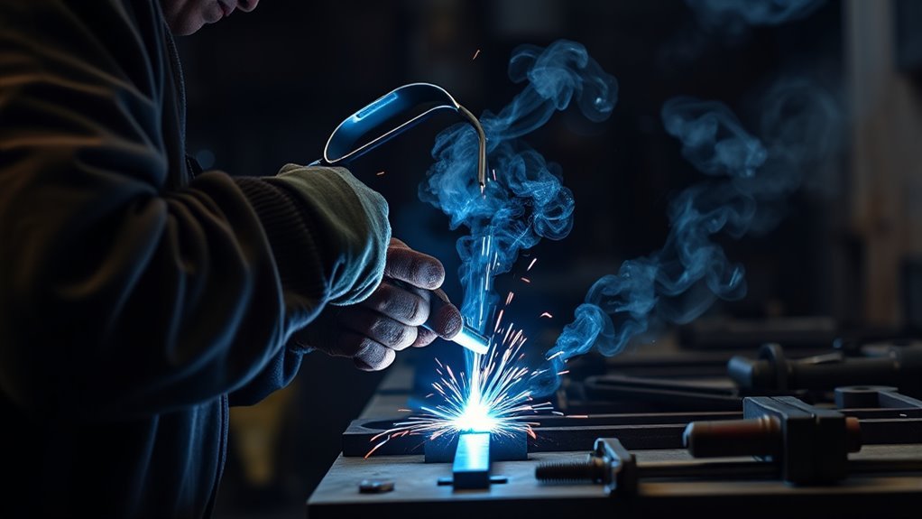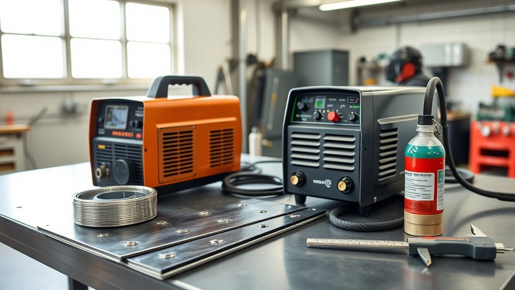
Auto body welding can go wrong fast when a machine puts too much heat into thin metal. The right welder helps you make clean repairs without burn-through, weak fusion, or warped panels. For most nonstructural mild-steel body work, low-end arc stability, fine voltage control, solid wire, and shielding gas matter more than the largest amperage number on the front of the machine.
Quick Answer
For nonstructural mild-steel body panels, start with a gas-shielded MIG welder that has a stable low-end arc, accepts 0.023- or 0.024-inch solid wire, and reaches roughly 120 to 140 amps. A 120V machine is usually enough for sheet metal; choose a dual-voltage 180-amp-class unit when you also weld thicker brackets or fabrication steel.
Key Takeaways
- For thin body panels, smooth low-output performance matters more than maximum amperage.
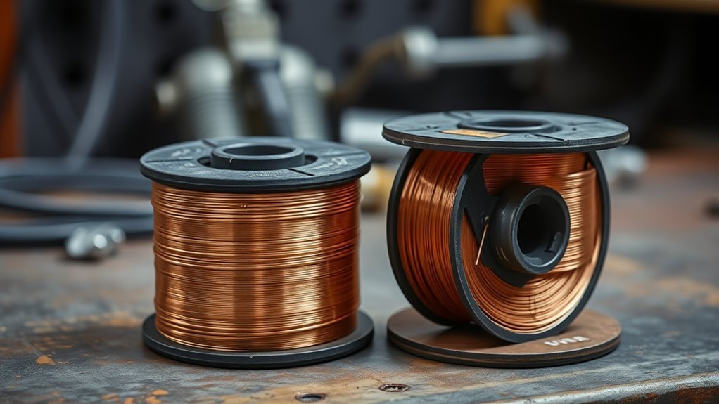
- Use 0.023- or 0.024-inch solid wire with C25 shielding gas as a practical starting setup for ordinary mild steel.
- A 120V MIG welder can handle most cosmetic panel repairs; dual-voltage equipment adds capacity for thicker work.
- Do not select a welding process for rails, pillars, reinforcements, or other structural parts without checking the vehicle manufacturer’s repair procedure.
- Read duty cycle together with its rated amperage. A high percentage at low output is not the same as a high percentage at maximum output.
- Aluminum, stainless steel, HSS, UHSS, and OEM-specified MIG brazing require different wire, gas, equipment, or procedures.
Auto Body Welder Size: The Practical Starting Point
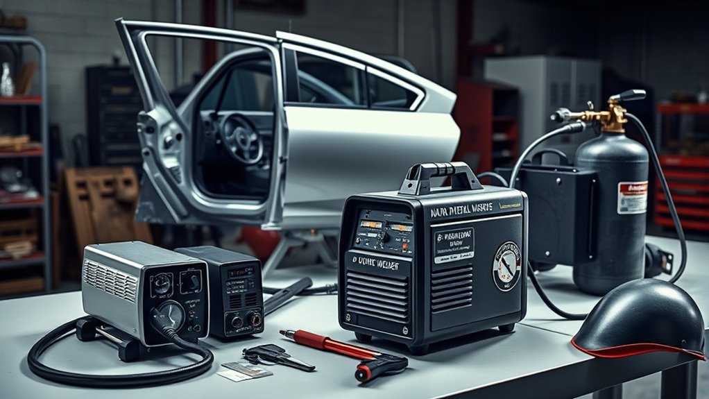
For ordinary nonstructural mild-steel panels, a 120V gas-shielded MIG welder with a maximum output in the 120- to 140-amp range is a practical starting point. That class of machine normally gives you enough capacity for patch panels, floor-pan work, and many light brackets without forcing you to install a 240V circuit.
The machine’s lowest usable setting is just as important as its maximum output. Look for a stable short-circuit arc at low wire speeds, fine voltage adjustment, and drive components made for 0.023- or 0.024-inch wire. A machine that reaches 200 amps but behaves poorly on light-gauge sheet may be less useful for body panels than a well-controlled 120V model.
If your work regularly includes thicker nonstructural brackets, shop fabrication, exhaust components, or repeated welding at higher settings, a 180- to 210-amp dual-voltage machine offers more reserve. It does not automatically weld thin panels better, but it gives you a wider operating range and usually a more useful duty cycle at higher output.
Some manufacturers advertise individual 140-amp machines as capable of welding from 24-gauge steel up to 1/4 inch. Treat that as a model-specific capability under stated conditions, not proof that every 140-amp welder can make every 1/4-inch joint safely. Joint design, wire, shielding gas, preparation, welding position, number of passes, and structural requirements all affect the result.
A multi-process unit can be useful when you genuinely need MIG and TIG capability. Check the details before buying: many compact multi-process machines provide only DC TIG, which is not the same as having AC TIG for common aluminum work. A spool-gun connection may be more useful than TIG mode when your main goal is occasional aluminum MIG welding.
The best auto-body welder is not necessarily the machine with the highest amperage. It is the machine that starts cleanly, feeds small wire smoothly, and gives you repeatable control at the lowest settings you use.
Welder Selection at a Glance
| Nonstructural outer panels | Gas-shielded 120V MIG with a stable low-end arc, 0.023- or 0.024-inch solid wire, and roughly 120–140 amps of maximum output. |
| Panels plus thicker shop work | A 180- to 210-amp dual-voltage MIG offers more output and duty-cycle capacity while retaining panel capability. |
| Structural unibody or frame work | Use only the welding process, wire, gas, joint design, and equipment specified by the vehicle manufacturer’s body repair information. |
| Aluminum panels | Use an aluminum-capable spool-gun or push-pull MIG system, or a suitable AC TIG welder, with the correct filler alloy and shielding gas. |
| Occasional home use | A modest duty cycle can be adequate because panel welding uses short, separated tacks rather than long continuous beads. |
Separate Outer-Panel Work From Structural Repair
Before choosing a welder, decide whether the repair is cosmetic, nonstructural, or structural. A mild-steel patch in an older fender is not the same job as replacing a pillar reinforcement, rail, rocker reinforcement, crush-zone component, or suspension mounting structure.
Modern vehicle bodies can contain several steel strength grades, aluminum, castings, adhesives, rivets, factory spot welds, and tailored blanks in the same assembly. Heat that is acceptable on an ordinary outer panel can weaken a high-strength structural part or change how the body performs in a later collision.
Always identify the vehicle, model year, component, material, and approved joining method in the manufacturer’s body repair information. Honda’s current body-repair welding and sectioning guidance, for example, limits welding methods by steel strength and requires welding wire with adequate tensile strength. It states that ordinary ER70S-6 wire can be used only through 440 MPa steel under those procedures.
Stronger steel may require high-strength wire, squeeze-type resistance spot welding, pulsed MIG brazing, restricted plug welding, or complete component replacement. Sectioning may be prohibited even when the damaged area looks weldable.
Warning: Do not repair a structural rail, pillar, reinforcement, rocker structure, bumper beam, seat-belt mounting area, suspension mounting area, or UHSS component based only on a generic amperage chart. Follow the exact OEM repair procedure or refer the repair to a properly equipped collision facility.
Match Welder Output to Panel Thickness
Material thickness is a useful starting point, but it is not the only factor that sets MIG output. Joint type, fit-up, wire diameter, wire-feed speed, shielding gas, welding position, travel speed, and the machine’s arc characteristics all affect how much heat reaches the panel.
A commonly published starting rule for mild-steel MIG welding is about 1 amp for every 0.001 inch of material thickness. That suggests roughly 30 amps for 0.030-inch steel and 125 amps for 0.125-inch steel. Use those figures only as rough starting points. MIG amperage is closely tied to wire-feed speed, while voltage controls arc length and strongly affects bead width and profile.
Begin with the settings chart inside the welder, the owner’s manual, or a reliable manufacturer MIG parameter guide. Make test welds on scrap of the same material, thickness, coating condition, joint design, and position before touching the vehicle.
- Light-gauge outer panels: Favor the smallest supported solid wire, the lowest stable short-circuit setting, tight fit-up, and separated tacks.
- 18-gauge and heavier mild steel: Depending on the machine and joint, 0.023-, 0.024-, or 0.030-inch wire may work. Follow the machine chart and test the joint.
- Thicker nonstructural brackets: More output, larger wire, joint preparation, or multiple passes may be needed.
- Structural automotive steel: Material thickness alone is not enough. Steel strength and the OEM joining procedure control the process and consumables.
Do not transfer settings directly from a stick-welding amperage chart to a MIG machine. Stick electrode diameter and MIG wire-feed speed control current in different ways.
Warning: Excess heat can burn through sheet metal, enlarge the heat-affected zone, pull panel edges out of alignment, and leave permanent oil-canning or distortion.
Products Worth Considering
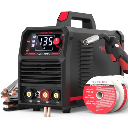
READY OUT OF THE BOX: Start welding immediately! It masterfully handles Gasless Flux Core MIG, Stick, and Lift TIG (Extra Lift TIG torch required). This budget-friendly 3-in-1 machine includes extra E71T-GS .030''&.035'' flux core wires, known for its smooth arc and high feedability. Say goodbye to heavy shielding gas cylinders—perfect for outdoor, windy, or all-position welding.

【LOW SPATTER & EASY CLEANUP】Minimal Spatter, Flawless Beads: Experience exceptionally low spatter and minimal post-weld cleanup. This ER70S-6 solid wire allows you to achieve smooth, visually appealing beads with ease, saving both time and grinding effort on your metal fabrication.

5-in-1 covers all your welding needs — from thin sheet metal to thick steel. Pulse mode delivers smoother MIG welds with less spatter. SPOT welding handles auto body panels without burn-through. Synergic control auto-matches current to wire speed — no more guesswork. One machine replaces three, saves $400+ on tool costs
Why Gas-Shielded MIG Works Best for Most Body Panels
Gas-shielded MIG works well for ordinary mild-steel body panels because it is relatively easy to learn, feeds filler metal continuously, and can run a controlled short-circuit arc. It also allows you to make a series of small tacks instead of holding a continuous arc on heat-sensitive sheet.
For light-gauge mild steel, Miller’s thin-sheet guidance recommends 0.023- or 0.024-inch wire. The smaller wire melts with less heat and gives the operator more control over deposition. On suitable thicker sheet, 0.030-inch wire may be appropriate.
ER70S-6 is a common solid wire for ordinary mild steel because its deoxidizers help it tolerate minor surface contamination. The joint must still be cleaned to bright, sound metal. Paint, rust, adhesive, undercoating, seam sealer, oil, and scale can cause porosity, unstable arc behavior, fumes, and weak fusion.
For common mild-steel short-circuit MIG, C25 shielding gas—75% argon and 25% carbon dioxide—usually provides a smooth arc, modest penetration, and less spatter than straight carbon dioxide. Run solid wire on direct-current electrode positive unless the machine or consumable manufacturer states otherwise.
Use short tacks and distribute them around the repair rather than completing one area at a time. This skip-welding sequence lets heat spread and dissipate. A slight push angle can also help reduce penetration and keep the arc directed toward the cooler leading edge of the puddle.
For a complete repair sequence, see how to weld sheet metal on a car. If gas is unavailable, these flux-core welding tips for beginners explain the process, but self-shielded flux core should not be your first choice for visible thin body panels. Its harsher arc, greater heat input, slag, and spatter make burn-through and cleanup harder to control.
When TIG Makes Sense for Automotive Work
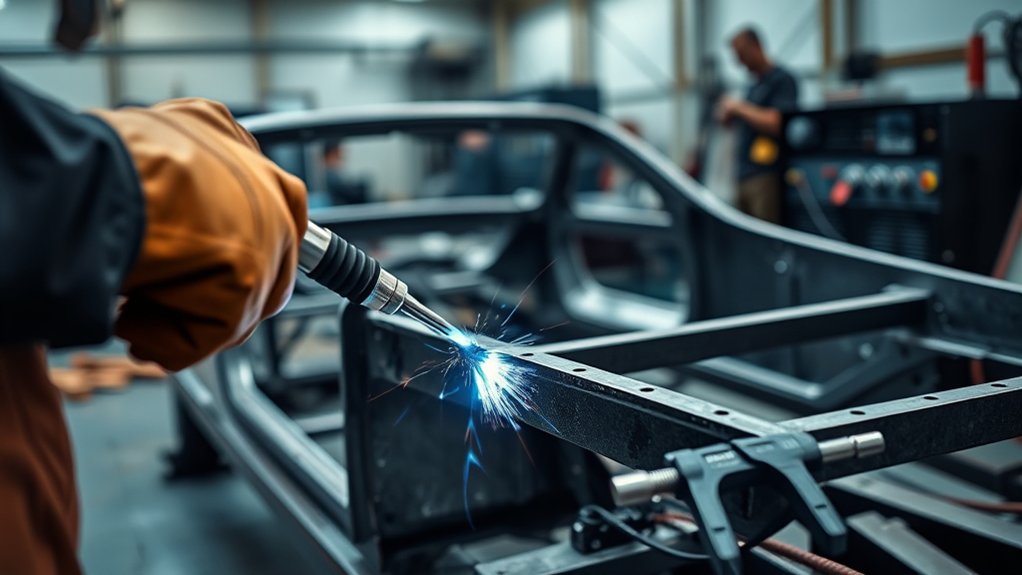
TIG gives the operator precise control of the arc and filler rod, but it is not automatically the correct process for a structural frame or unibody repair. Use TIG only when the base metal, joint, repair procedure, and operator skill make it appropriate.
Where TIG Can Help
TIG is useful for clean custom fabrication, thin stainless components, carefully fitted mild-steel parts, and aluminum work performed with suitable AC equipment. It produces no wire-feed spatter and allows the operator to add filler only when needed.
A 150-amp TIG machine can cover many thin steel and stainless projects, but its output rating does not qualify it for a collision-structure repair. For aluminum, check the machine’s AC output, duty cycle, balance control, and recommended thickness range rather than relying on the front-panel amperage alone.
Use the correct filler rod for the exact base metal and a shielding gas specified for the TIG process, commonly pure argon for many automotive steel, stainless, and aluminum applications. Cleanliness and tight fit-up are critical because TIG does not hide contamination or large gaps.
- Use a small, stable arc on thin material.
- Match the filler alloy to the base metal.
- Keep the joint clean and tightly fitted.
- Control travel speed to limit heat buildup.
- Practice torch and filler coordination before welding the vehicle.
If a project involves stainless material, compare TIG and MIG requirements with the process limitations discussed in this guide to stick welding stainless steel.
Why Frame Repairs Require OEM Procedures
A clean-looking TIG bead does not prove that a structural joint is safe. Collision structures are engineered around specific materials, weld locations, weld counts, hole sizes, adhesives, overlap dimensions, and heat-affected zones.
An OEM procedure may call for squeeze-type resistance spot welding, MAG plug welds, high-strength wire, pulsed MIG brazing, rivet bonding, or complete part replacement. It may prohibit butt welding, open-flame heating, or sectioning in the damaged area.
MIG brazing is also different from ordinary steel MIG welding. It commonly uses silicon-bronze wire, lower heat, and pure argon, and it should be performed only where the manufacturer specifies the joint and equipment. It is not a substitute that can be applied anywhere heat reduction seems useful.
Note: In automotive repair literature, “MIG,” “MAG,” and “MIG brazing” may describe different gases, filler metals, and joining mechanisms. Use the terminology and procedure stated by the vehicle manufacturer.
Choose 120V or 240V for Your Shop
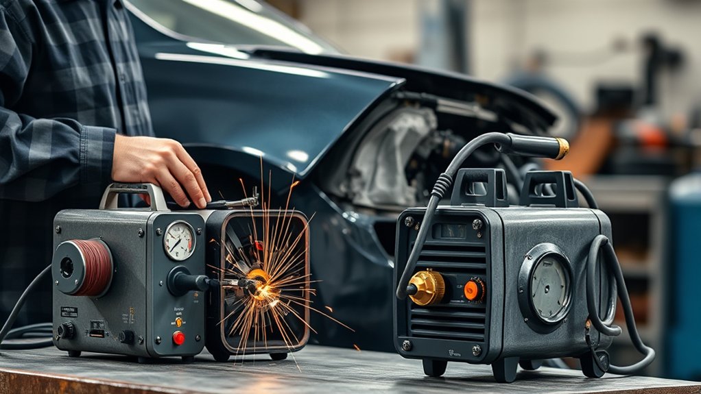
Input voltage determines how much electrical power the machine can draw, but it does not by itself determine weld quality. Compare the actual output range, low-end arc behavior, controls, wire capability, and duty-cycle rating of each machine.
120V for Light-Duty Panel Work
A gas-capable 120V MIG welder is usually enough for rust patches, quarter-panel sections, floor pans, and other ordinary mild-steel sheet-metal work. It is portable, fits many home garages, and avoids the cost of installing a 240V receptacle when the existing circuit meets the welder manufacturer’s requirements.
- Suitable for most thin-panel repairs
- Portable and easy to store
- Lower initial electrical setup cost
- Available with 0.023- and 0.024-inch wire support
- Often adequate for beginner and occasional restoration work
Do not assume that every household receptacle is suitable merely because the plug fits. Check the welder’s required branch circuit, breaker, receptacle, conductor size, and extension-cord limits. Have a qualified electrician correct an undersized or questionable circuit.
240V for Higher Output
A 240V machine becomes useful when the work regularly extends beyond thin panels into thicker brackets, fabrication steel, repeated plug welds, or longer welding periods. The larger input supply can support more maximum output and a stronger duty-cycle rating.
That extra capacity does not guarantee smoother low-end performance. Compare the machine’s minimum output, voltage steps or infinite control, wire-feed system, and published thin-material range before assuming that a larger power source is better for sheet metal.
A dual-voltage unit is a useful compromise. You can run it on 120V for portable panel work and connect it to 240V when the job requires higher output. Always check whether the machine’s output and thickness ratings change with the selected input voltage.
Circuit and Duty Cycle
Duty cycle is the percentage of a ten-minute test period that a welder can operate at a stated amperage and voltage without exceeding its thermal rating. A 20% duty cycle at a specified output means two minutes of arc time followed by the required cooling period under the manufacturer’s test conditions.
Always compare both parts of the rating. “60% duty cycle” has little meaning unless you know the amperage and voltage at which it was measured. As one real-world example, the published Hobart Handler 140 specification lists 20% duty cycle at 90 amps, not 60% at maximum output.
A modest duty cycle can still be adequate for outer-panel repairs because proper technique uses short tacks separated by cooling time. A higher duty cycle becomes more valuable during sustained fabrication, repeated plug welding, thicker joints, or professional production work.
- 120V is often sufficient for cosmetic sheet-metal repair.
- 240V supports greater output and sustained workload.
- Dual-voltage machines provide flexibility.
- Duty-cycle percentage must be read with its rated output.
- The owner’s manual controls circuit and extension-cord requirements.
When your work includes thicker fillet joints, use correct preparation and understand fillet weld sizing for the material thickness. Do not compensate for poor joint design by simply increasing amperage.
Choose Wire, Gas, Polarity, and Consumables
Wire and shielding gas must match the base metal and the approved repair process. The common mild-steel panel setup is not suitable for every automotive material.
- Light-gauge mild steel: Start with 0.023- or 0.024-inch ER70S-series solid wire, C25 gas, and electrode-positive polarity.
- Heavier ordinary mild steel: Depending on the joint and machine chart, 0.030-inch wire may provide a useful operating range and faster deposition.
- Stainless steel: Match the filler wire to the stainless alloy and use the shielding gas recommended by the wire or equipment manufacturer.
- Aluminum: Match the filler alloy to the base metal and use an aluminum-capable feeding system. Pure argon is common for MIG and TIG aluminum work.
- OEM MIG brazing: Use only the specified pulsed equipment, silicon-bronze wire, gas, joint design, and settings.
- HSS and UHSS: Use the wire strength and welding method stated in the model-specific body repair procedure.
C25 is a strong general-purpose choice for ordinary mild-steel panel work because it produces a smooth short-circuit arc with less spatter than straight carbon dioxide. Do not use it automatically for aluminum, stainless steel, or MIG brazing.
The 1-amp-per-0.001-inch rule may suggest about 125 amps for 1/8-inch ordinary steel, but it remains only a starting estimate. Follow the machine chart, account for the joint, and confirm fusion with representative test pieces.
Coated and galvanized automotive steel require additional controls because heat can release hazardous fumes. Review these MIG welding galvanized steel safety precautions, remove coatings only as permitted by the repair procedure, and use effective ventilation and respiratory protection where required.
Pro Tip: Practice on scrap cut from the replacement panel or on material with the same alloy, thickness, coating condition, joint design, and welding position. A setting that works on clean bench steel may behave differently on an installed vehicle panel.
Prepare the Vehicle and Control Heat
A suitable welder cannot compensate for poor preparation. Before welding, inspect both sides of the repair and identify every system or material that heat, sparks, current, and grinding debris could damage.
- Check the OEM repair information. Confirm the component material, allowed sectioning location, joint type, weld count, consumable, and corrosion-protection procedure.
- Disable electrical and restraint systems correctly. Follow the manufacturer’s battery, SRS, pretensioner, hybrid, and EV high-voltage shutdown procedures, including all specified waiting periods.
- Protect fuel and fluid systems. Locate fuel, brake, vapor, hydraulic, and refrigerant lines before cutting or welding. Do not weld near a leak, vapor source, pressurized line, or closed container.
- Remove hidden combustibles. Inspect carpet, foam, insulation, seam sealer, cavity wax, sound deadener, wiring, trim, and undercoating on the opposite side of the panel.
- Clean the weld zone. Remove paint, rust, adhesive, sealer, oil, and prohibited coatings far enough from the joint to produce clean fusion and reduce fumes.
- Place the work clamp carefully. Attach it to clean metal close to the weld when permitted, avoiding current paths through bearings, modules, hinges, or sensitive systems.
- Prepare fire controls. Keep a suitable extinguisher nearby, shield adjacent material, and inspect hidden cavities repeatedly during and after welding.
- Restore corrosion protection. After inspection and finishing, apply the seam sealer, primer, cavity wax, adhesive, and topcoat required by the repair procedure.
Primer instructions depend on the joining process. For example, Honda’s body-repair guidance states that weld-through primer should not be used for its MAG plug, MAG butt, or MIG-brazed joints and calls for epoxy primer over the completed exposed steel. Do not assume one primer procedure applies to every manufacturer or welding method.
Warning: Welding can ignite fuel vapor, seam sealer, foam, carpet, undercoating, adhesive, cavity wax, and hidden debris long after the visible arc stops. It can also damage airbags, pretensioners, electronic modules, refrigerant lines, and high-voltage components. Follow the vehicle manufacturer’s disable and repair procedures before work begins.
Heat Control for Thin Panels
Tight fit-up is the first defense against burn-through. A gap that looks small on a thick fabrication joint can be large enough to destroy the edge of a body panel. Trim the patch carefully and keep the edges aligned before tacking.
Place initial tacks far apart, then return to fill spaces only after the surrounding metal cools. Continue moving around the panel instead of creating a continuous hot zone. Check alignment and panel shape after each sequence.
A clean copper backing bar can support the puddle, absorb heat, and reduce the chance of blowing a hole where the back of the joint is accessible. Keep the bar tight against the panel and make sure it cannot trap contamination in the joint.
Do not run a continuous bead across an outer butt joint merely to finish faster. Continuous welding concentrates heat and can shrink the seam enough to warp a large section. Do not quench structural high-strength steel unless the OEM procedure expressly permits it.
Auto Body Welder Buying Checklist
Compare these features before choosing a machine:
- Low-end output: Look for a published light-gauge rating and a stable short-circuit arc near the machine’s minimum output.
- Small-wire support: Confirm that the drive roll, liner, contact tips, and gun support 0.023- or 0.024-inch solid wire.
- Gas capability: Choose a machine with the required gas solenoid, regulator connection, and polarity change for solid-wire MIG.
- Fine adjustment: Infinite or closely spaced voltage control and smooth wire-feed adjustment help with thin panels.
- Input power: Match 120V, 240V, or dual-voltage capability to the available circuit and future workload.
- Duty cycle: Compare the percentage at the amperage you expect to use, not only the largest percentage in the brochure.
- Material support: Check for a spool-gun connection, pulsed MIG, AC TIG, or other features only when your intended materials require them.
- Consumables and service: Choose a gun and feeder with readily available tips, nozzles, liners, rolls, and repair support.
- Setup chart: A clear door chart or reliable automatic setup system gives useful starting parameters, but test welds are still required.
- OEM capability: Professional collision work may require squeeze-type resistance spot welding, pulsed MIG brazing, high-strength wire, and documented weld testing beyond the capability of a hobby MIG machine.
Products Worth Considering

【LOW SPATTER & EASY CLEANUP】Minimal Spatter, Flawless Beads: Experience exceptionally low spatter and minimal post-weld cleanup. This ER70S-6 solid wire allows you to achieve smooth, visually appealing beads with ease, saving both time and grinding effort on your metal fabrication.

【LOW SPATTER & EASY CLEANUP】Minimal Spatter, Flawless Beads: Experience exceptionally low spatter and minimal post-weld cleanup. This ER70S-6 solid wire allows you to achieve smooth, visually appealing beads with ease, saving both time and grinding effort on your metal fabrication.
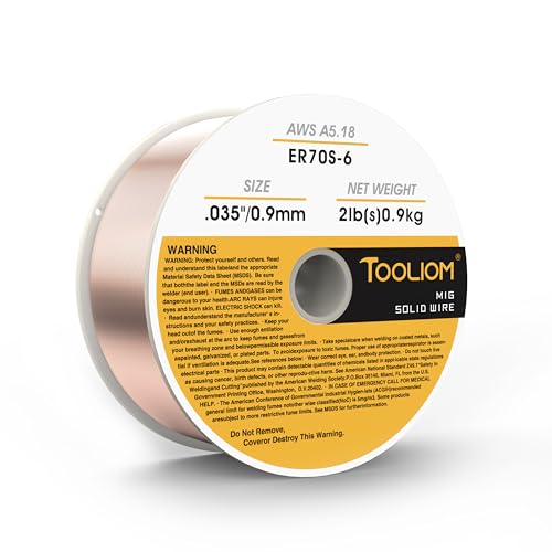
High-quality:Tooliom's .035" ER70S-6 MIG Welding Wire (2lb spool) meets all industry standards for consistent strength and performance. Enjoy smooth feeding, stable arcs, optimal penetration, and high deposition rates—everything you need for exceptional welds
Frequently Asked Questions
What size welder do you need for automotive body work?
For ordinary nonstructural mild-steel panels, a gas-shielded 120V MIG welder with stable low-output performance, support for 0.023- or 0.024-inch wire, and roughly 120–140 amps of maximum output is a practical choice. Choose more capacity only when your work includes thicker material or sustained welding.
What type of welder is best for auto body work?
Gas-shielded MIG is usually the best starting process for ordinary mild-steel body panels because it is relatively easy to learn and works well with short, separated tacks. TIG can suit precise custom work, stainless steel, or aluminum, while structural collision repairs must follow the OEM-specified joining method.
Is a 140-amp MIG welder enough for auto body repair?
A well-designed 140-amp MIG is normally enough for nonstructural sheet-metal repair and many light brackets. Its minimum output, voltage control, wire-feed stability, gas capability, and thin-material rating matter more than the 140-amp number alone.
Is 0.030- or 0.035-inch wire better for auto body panels?
Neither is ideal for the thinnest visible panels when the machine supports smaller wire. Use 0.023- or 0.024-inch solid wire for the best low-heat control. A 0.030-inch wire may suit thicker sheet, while 0.035 inch is generally better reserved for heavier material.
Is it better to weld auto body panels with 110V or 220V?
A nominal 110V or 120V welder is usually sufficient for light panel repair. A nominal 220V or 240V supply supports more output and sustained workload, but it does not automatically improve low-end control. A dual-voltage machine is useful when you need both portability and thicker-material capacity.
Can you use flux-core wire for auto body panels?
Flux-core wire can join some sheet metal, but it is harder to control on thin visible panels because it generally creates more heat, spatter, slag, and cleanup. Gas-shielded MIG with small solid wire usually gives a smoother arc and a lower risk of burn-through.
Can the same MIG welder repair aluminum body panels?
Only when the machine supports the required aluminum wire-feeding system and settings. Aluminum commonly needs a spool gun or push-pull gun, the correct filler alloy, and pure argon. Some OEM aluminum repairs use rivets and adhesive instead of fusion welding, so check the body repair manual first.
Can a hobby MIG welder be used for frame or unibody repairs?
Do not assume that it can. Structural repairs may require OEM-approved wire, pulsed MIG brazing, squeeze-type resistance spot welding, weld testing, adhesives, or complete part replacement. Use the model-specific body repair procedure and qualified collision-repair equipment.
Safety Disclaimer: This article is for informational purposes only and does not replace professional welding training, a welder owner’s manual, or model-specific vehicle repair information. Welding can cause burns, fire, hazardous fumes, eye injury, electrical shock, electronic damage, and unsafe structural repairs. Use suitable PPE, ventilation, fire controls, and OEM procedures. Refer safety-critical or structural work to a qualified collision-repair professional.
Conclusion
For ordinary nonstructural mild-steel body panels, start with a gas-shielded MIG welder that feeds 0.023- or 0.024-inch wire smoothly and produces a stable arc at low output. A well-controlled 120V machine in the 120- to 140-amp class is enough for most cosmetic panel work.
Choose a dual-voltage 180-amp-class machine when you also need to weld thicker nonstructural steel or work for longer periods. Do not buy solely by maximum amperage, advertised plate thickness, or duty-cycle percentage. Compare the minimum output, controls, gas capability, wire system, rated output, and available electrical circuit.
Most importantly, separate ordinary sheet-metal restoration from structural collision repair. Rails, pillars, reinforcements, HSS, UHSS, aluminum structures, and safety-system mounting areas must be repaired with the materials and joining methods specified by the vehicle manufacturer.
Sources
- Miller Electric — Successfully Welding Sheet Metal With MIG and TIG — supports small-wire selection, C25 use, heat control, skip welding, fit-up, and backing-bar guidance.
- Miller Electric — MIG Basics for Automotive Welding Repair — supports automotive wire ranges, shielding-gas selection, machine setup, and welding techniques.
- Miller Electric — Setting the Correct MIG Parameters — supports the amperage starting rule and voltage and wire-feed adjustment guidance.
- Hobart Welding Products — Handler 140 Specification — provides a real example of output range, advertised material capacity, input requirements, and duty cycle.
- Honda — Body Repair Manual Welding and Sectioning Guideline Revisions — supports OEM-specific HSS/UHSS procedures, wire-strength requirements, and primer restrictions.
- Occupational Safety and Health Administration — Welding, Cutting, and Brazing Hazards — supports fume, radiation, burn, eye, electrical, and PPE precautions.