
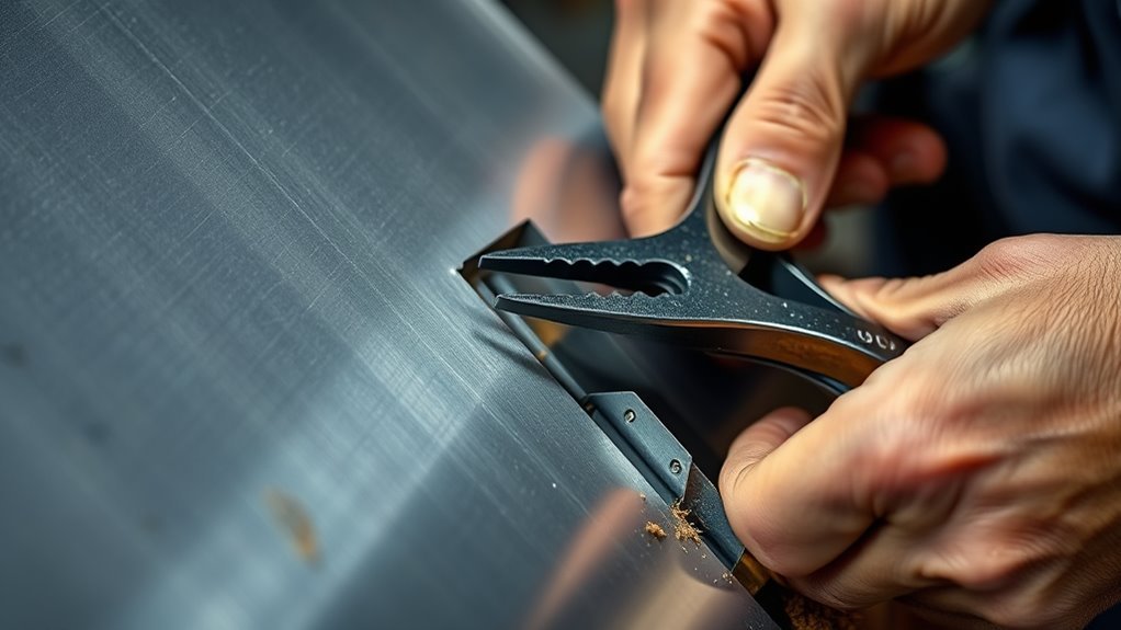
A flat sheet-metal seam starts with choosing the right joint before you cut or bend anything. A true butt joint keeps both panel edges in the same plane. If you form a shallow offset flange so one panel overlaps the other, you have created a flush lap or joggled joint instead. Both methods can work, but they require different fit-up, welding, and corrosion-protection steps.
Quick Answer
Do not bend one panel to 90 degrees and call it a butt weld. A true butt joint keeps both sheet-metal edges in the same plane. If the repair procedure allows a flange, use a shallow offset or joggle to create a flush lap joint, then weld it by the specified method.
Key Takeaways
- An open butt joint has two edges aligned in the same plane. It does not use a 90-degree flange.
- A panel flanger or joggler creates a shallow offset for an overlapping lap joint.
- Use the joint dimensions and attachment method specified by the drawing, welding procedure, or vehicle manufacturer.
- Light-gauge steel needs close fit-up, low heat input, short tacks, and cooling time.
- Finish the job by inspecting the weld and restoring corrosion protection on both sides.
At a Glance
| Time Required | About 45 to 90 minutes for a small seam, plus additional cooling, grinding, inspection, and coating time |
| Difficulty | Intermediate; practice on matching scrap before welding the finished panel |
| Tools Needed | Layout tools, sheet-metal cutter, deburring tools, clamps, MIG welder, PPE, and an optional panel flanger or backing bar |
| Cost | Low consumable cost if you already own the tools; replacement steel, gas, wire, abrasives, and coating materials are additional |
Before You Begin
Plan the complete job before you strike an arc. Sheet metal expands while it heats and shrinks as it cools, so poor fit-up or concentrated heat can pull a straight seam out of shape.
Choose the Correct Joint
Start by identifying the joint required by the drawing, welding procedure specification, or repair manual. The joint name describes how the pieces meet, not simply the type of bead you place on them.
- Open butt joint: Two panel edges sit in the same plane and meet closely along the seam. There is no overlapping flange.
- Butt joint with backing: The main panel edges remain in the same plane, while a separate backing strip supports the joint from behind. The required root gap and backing dimensions come from the applicable procedure.
- Flanged or joggled lap joint: A shallow offset lets one panel overlap another while keeping the visible faces close to flush. This is a lap joint, not an open butt joint.
- Corner joint: The panels meet at an angle. Bending one edge 90 degrees creates this type of geometry rather than a standard flat butt joint.
The American Welding Society shows butt, corner, lap, T-, and edge joints as separate basic configurations. I-CAR also distinguishes open butt joints, butt joints with backing, and lap joints in collision-repair procedures. See the AWS welding symbol chart and I-CAR sectioning-joint terminology.
Choose the joint first. Flanging changes the joint configuration, so it should never be treated as a substitute for accurate butt-joint fit-up.
Warning: For vehicle pillars, rocker panels, rails, structural members, advanced high-strength steel, or areas near restraints and high-voltage components, use the current vehicle-specific body repair manual. Do not invent a flange, backing strip, sectioning location, or weld pattern.
What You’ll Need
- Square, straightedge, marker, or scribe for layout
- Metal shears, snips, cutoff wheel, plasma cutter, or CNC cutter suitable for the material
- File, deburring tool, surface-conditioning disc, or flap disc
- Panel flanger or joggler if the approved joint requires an offset lap
- Brake or forming tool when the design requires a separate bend
- Butt-weld clamps, panel clamps, magnets, or other suitable fixtures
- MIG welder with the correct polarity, contact tip, wire, and shielding gas
- Matching scrap metal for setup tests
- Copper or aluminum backing bar when backside access and joint design allow it
- Welding helmet, safety glasses, gloves, protective clothing, hearing protection, and suitable footwear
- Local exhaust or other ventilation appropriate to the metal and coatings
- Fire extinguisher and fire-resistant covers or screens
- Primer, seam sealer, cavity coating, or other corrosion-protection products specified for the finished assembly
Warning: Identify all coatings before grinding or welding. Zinc oxide from galvanized steel can cause metal fume fever, and older paint or plating may contain additional hazardous substances. Remove coatings from the direct weld zone, use suitable ventilation, keep your head out of the fume plume, and follow the product safety data sheets.
OSHA identifies welding fumes, ultraviolet radiation, burns, electrical shock, and fire as significant hot-work hazards. Remove or shield combustible material, inspect the opposite side of the work, and keep suitable fire-extinguishing equipment ready. Review OSHA welding hazards and controls before starting.
Cut the Sheet Metal Edges Cleanly
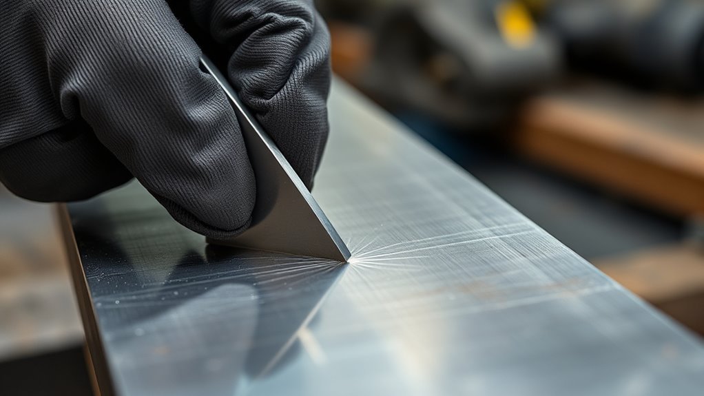
Start by measuring and marking the cut lines with a square, straightedge, or template. A true edge gives you a better chance of achieving uniform fit-up without forcing the panels together.
Use sharp shears or snips when the material and cut shape allow it. Hold the tool at a steady angle and support the panel so the cutting action does not curl or stretch the edge.
For thicker sheet or complex shapes, use a cutoff wheel, plasma cutter, or CNC machine suitable for the material. Leave enough material for final trimming instead of trying to make an irreversible finish cut on the first pass.
After cutting, deburr both sides with a file or suitable abrasive. Remove sharp edges, slag, and high spots without rounding the edge excessively. A rounded or thinned edge is harder to align and easier to burn through.
Clean the weld zone to bright metal. Remove rust, scale, oil, adhesive, seam sealer, paint, and coating far enough from the seam to prevent contamination. When working with coated steel, follow safe procedures for removing all zinc residues from the direct weld area.
Note: A cutting tool can leave a heat-affected edge, taper, burr, or distortion. Check the edge with a straightedge and correct it before forming or clamping the joint.
Products Worth Considering
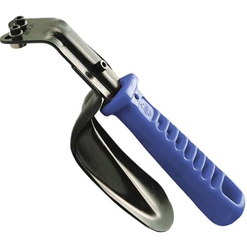
SKU# 515-0626

DB1000 Double Edge Cutting Deburring Tool

【29-piece Deburring Tool Set】1 blue metal knurled handle + 11 high-speed steel replacement blades + 7 needle files + 10 pieces of dry and wet sandpaper to meet the needs of different jobs, comes with a plastic box for dust-proof storage.
Form an Offset Flange Only for a Lap or Joggled Joint
If the design requires a true open butt joint, do not flange either panel. Trim and align the edges in the same plane.
If the approved design requires a flush lap joint, use a panel flanger or joggler to form a shallow offset along one panel. The offset depth should closely match the thickness of the overlapping sheet so the exposed faces sit near flush after assembly.
Do not bend the edge to 90 degrees unless the drawing calls for a corner, return, or mounting flange. A 90-degree lip does not create a standard flat butt-joint seam.
The required flange width is not universal. It may be determined by the tool’s jaw, the overlap specified on the drawing, the weld type, plug-weld locations, adhesive requirements, or the vehicle manufacturer’s procedure. A handheld flanger may create a relatively narrow offset, while an OEM sectioning procedure may specify a substantially wider overlap.
Keep the formed area even from end to end. An inconsistent offset causes high-low misalignment, leaves gaps under the overlap, and makes clamping difficult.
Clean the flange and mating panel before assembly. Oil, grit, oxide, paint, and excessive weld-through primer in the direct arc path can contribute to porosity or unstable welding. Wear suitable protective clothing for arc welding while forming, grinding, and welding the panel.
Pro Tip: Form the offset on scrap of the same thickness first. Place a second scrap panel in the joggle and check both face alignment and clamping pressure before touching the finished part.
Fit the Panels Flush Before Welding
Clean fit-up is more important than trying to compensate with extra wire. Clamp the panels without forcing them into a stressed position, then check the complete seam with your fingertips, a straightedge, and good lighting.
Fit an Open Butt Joint
Keep both panel faces in the same plane and maintain a close, consistent edge fit. On very light 20- to 24-gauge sheet, Miller notes that a 1/16-inch opening acts like a hole and greatly increases burn-through risk. Do not use 1/16 inch as a target gap for a light-gauge open butt seam.
A small root opening may be required for some processes or engineered joints, but the dimension must come from the drawing, welding procedure, or repair manual. Do not guess.
Fit a Butt Joint With Backing
Use the specified backing material, width, thickness, coating, and root gap. I-CAR describes one automotive butt-with-backing configuration that uses backing of similar thickness and a root opening of roughly two to three sheet thicknesses. That example does not replace a vehicle-specific procedure.
Fit a Flanged Lap Joint
Seat the upper panel fully into the offset so the visible faces align. Confirm that the overlap remains consistent and that there are no trapped chips, heavy primer deposits, or unsupported gaps between the layers.
Use butt-weld clamps, panel clamps, or fixtures suited to the chosen joint. Recheck the complete seam after tightening because clamps can pull thin panels out of plane.
For vehicle work, review the full removal and installation procedure. A cut line that appears to indicate an open butt joint during removal may create a procedure-defined lap joint when the replacement panel is trimmed for installation. Proper automotive sheet-metal welding preparation includes checking these instructions before cutting.
Note: “Flush” describes the visible panel faces. It does not mean every joint should use zero root gap or the same overlap. Fit each joint according to its approved configuration.
Set Up Your Welder for Thin Sheet Metal
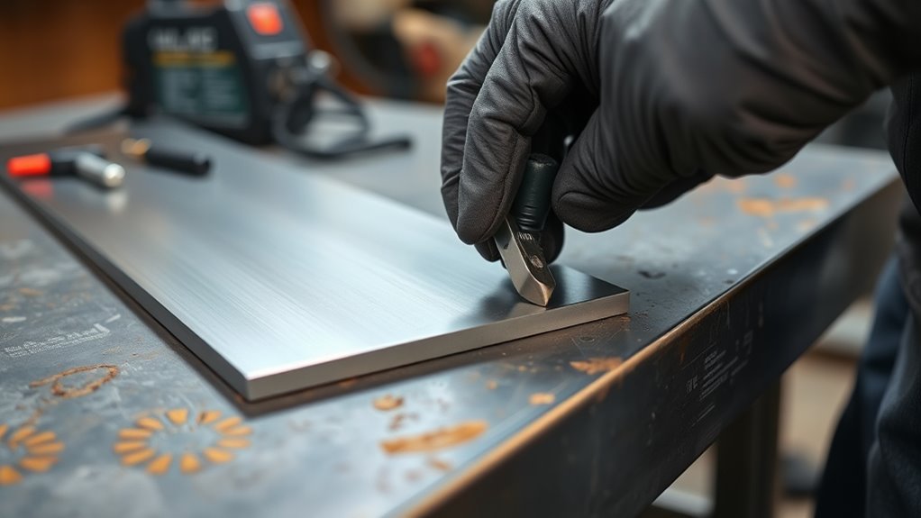
Do not copy dial positions such as “2.5,” “35%,” or “40” from another welder. Numbered voltage taps and percentage displays vary by manufacturer and model.
Start with the parameter chart inside the machine, the owner’s manual, or the manufacturer’s settings calculator. Select the base metal, actual sheet thickness, wire diameter, shielding gas, and joint type. Then test and fine-tune the settings on clean scrap that matches the finished panels.
- Polarity: Use the polarity specified for the wire. Solid steel MIG wire normally uses direct-current electrode positive.
- Wire: .023- or .024-inch solid wire is commonly recommended for light-gauge steel. Some machines can use .030-inch wire effectively on 18-gauge and thicker material.
- Gas: C25, which is 75% argon and 25% carbon dioxide, is a common choice for short-circuit MIG welding mild steel because it provides a stable arc and relatively low spatter.
- Contact tip and liner: Match them to the wire and confirm that the wire feeds smoothly without slipping or surging.
- Ground connection: Clamp to clean metal close enough to the work to provide a reliable circuit.
- Gun setup: Keep a consistent work angle, travel angle, and contact-tip-to-work distance.
Miller recommends .023- or .024-inch wire for most light-gauge sheet-metal work and emphasizes using the machine manual as the starting point for voltage and wire speed. Review its guides to welding sheet metal with MIG and setting MIG welding parameters.
Make several test tacks on scrap. The arc should start cleanly, fuse both edges, and leave a compact tack without a large hole or excessive buildup. Adjust voltage and wire speed together until the arc is stable. Maintain the correct arc length and wire stickout for your machine and process.
The chart gets you close. Matching scrap tells you whether the settings, fit-up, and technique actually work together.
Products Worth Considering

ER70S-6 MIG WIRE: It's the most common wire of the copper-coated mild steel GMAW (MIG) wires for single or multiple pass welding.

High-quality:Tooliom's .023" ER70S-6 MIG Welding Wire (10lb spool) meets all industry standards for consistent strength and performance. Enjoy smooth feeding, stable arcs, optimal penetration, and high deposition rates—everything you need for exceptional welds
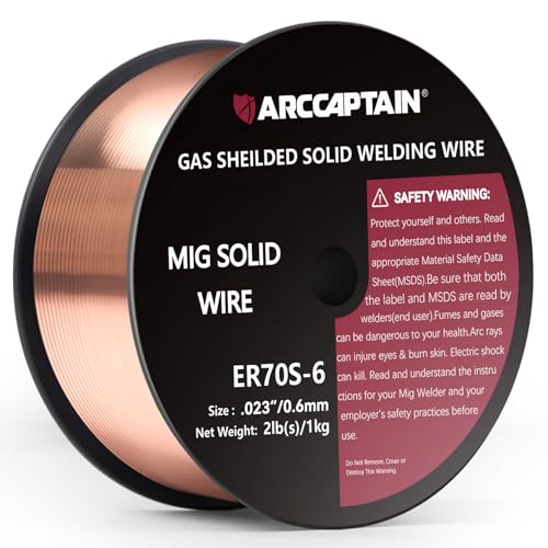
High-quality: ARCCAPTAIN's ER70S-6 mig welding wire .023" meets industry standards(Net Weight: 2lbs), ensuring consistent performance, superior strength. With its smooth feeding and stable welding parameters, you can achieve optimal penetration, high deposition rates, and exceptional overall welding performance.
Tack Weld the Seam in Short Bursts
Place the first tack near one end, then secure the opposite end so the panels cannot walk apart. Add a tack near the center, recheck alignment, and continue dividing the unsupported spaces.
A small seam may begin with six to eight tacks, but the correct number depends on seam length, panel shape, joint design, and how quickly the metal moves. For the auto-body butt-weld example in Miller’s procedure, the initial tacks are spaced no more than about 1 inch apart.
- Place a brief tack and release the trigger as soon as both edges fuse.
- Move to a distant, cool part of the seam rather than placing the next tack beside the first one.
- Check face alignment and root opening after every few tacks.
- Correct a high or low edge with clamps or careful hammer-and-dolly work before the seam becomes rigid.
- Allow the panel to cool until accumulated heat no longer spreads rapidly through the surrounding sheet.
Do not use compressed air or water automatically to force-cool every panel. Rapid or uneven cooling can introduce contamination or unwanted stress. Let the assembly cool naturally unless the approved process specifies another method.
Monitor your welding parameters and bead condition instead of relying on a fixed machine number. If each tack is tall and cold, correct the setup rather than grinding a weak seam flat later.
Pro Tip: Shine a light behind an accessible open butt seam after the initial tacks. Light leaking through an unexpected opening shows where fit-up needs correction before you add more heat.
Complete the Seam Without Warping
Once the panels remain aligned between the initial tacks, close the seam with short welds or overlapping tack-sized deposits. Do not run one continuous bead across a long, flat, light-gauge panel unless a proven procedure specifically calls for it.
Move around the seam so each new weld is placed in a relatively cool area. As the spaces become shorter, continue filling them without dwelling in one zone. Let the panel cool fully whenever you notice the heat-affected area spreading, the seam lifting, or the panel becoming difficult to touch near the work.
For an open butt seam, each deposit must fuse both panel edges. For a flanged lap joint, use the fillet, seam, plug-weld, adhesive, or combined attachment method shown by the design or repair procedure. Do not assume that a continuous edge weld is suitable for every overlapped panel.
Miller describes skip welding as a way to distribute heat and reduce distortion. Its auto-body example uses very short bursts, adding each new deposit at the end of a previous tack and allowing the panel to cool before continuing.
Fix Gaps, Burn-Through, and Warping
The Gap Opens Between the Panels
Stop welding and correct the fit-up. Trim a high point, reclamp the seam, or remake a badly fitted patch. Do not bridge a long opening with repeated wire deposits because the extra heat is likely to enlarge the hole and distort the surrounding panel.
The Weld Burns Through
Let the area cool, clean the damaged edge, and place a copper or aluminum backing bar behind the opening when access and joint design permit. The backing supports the molten pool and conducts heat away from the weld area.
Reduce the time the arc stays on the panel. Also check for excessive voltage, excessive wire speed or amperage, slow travel, a large root opening, thinned edges, rust, or poor gun position.
The Panel Develops High-Low Misalignment
Stop before the seam becomes fully locked. Release or reposition the clamps and use careful hammer-and-dolly work where appropriate. Adding more weld over a stepped joint will not make the finished panel flat.
The Weld Has Pinholes or Porosity
Remove the defective area and correct the cause. Check gas supply, regulator setting, hose leaks, nozzle blockage, wind, excessive gun distance, dirty base metal, contaminated wire, and coating trapped in the joint. Maintain proper shielding gas flow and MIG gun condition.
The Weld Sits High With Poor Fusion
A tall bead that sits on the surface may indicate insufficient heat, excessive travel speed, poor gun angle, or a tack that did not catch both edges. Do not grind it smooth and assume it is sound. Remove the defective section, adjust the setup on scrap, and reweld it.
The Panel Warps
Stop adding heat. Allow the panel to cool and determine whether the distortion comes from weld shrinkage, poor clamping, forced fit-up, or aggressive grinding. Correct the metal carefully before continuing. Severe distortion may require the joint to be cut apart and refitted.
Note: Copper backing can help with a small local opening, but it is not a substitute for correct panel size, joint geometry, or root-gap control.
Grind, Inspect, and Protect the Repair
After the seam has cooled, remove only the weld reinforcement that prevents the required finish. Use a controlled abrasive and keep it moving. Grinding can overheat and warp thin sheet metal just as welding can.
Do not grind deeply into the surrounding base metal. Thinning the panel beside the weld reduces strength and can create a visible low area. I-CAR advises remaining conscious of the base metal while dressing a butt weld.
Inspect the finished seam under bright light and from the backside when accessible. Look for:
- Cracks or crater cracks
- Pinholes and porosity
- Unfused edges
- Unexpected gaps or incomplete sections
- Excessive penetration or burn-through
- High-low panel alignment
- Overground or visibly thinned base metal
- Loose plug welds or unsealed overlap edges
Clean the completed repair and restore corrosion protection after the metal has cooled. Treat the backside, overlaps, cavities, and bare ground areas with the primer, seam sealer, cavity wax, adhesive, or coating specified for the assembly.
Weld-through primer is not a universal coating that should remain directly under every arc. I-CAR notes that OEM procedures may require it between mating surfaces while also requiring removal from the direct GMA weld locations. Follow the product instructions and the applicable repair procedure.
Warning: Never weld, cut, or grind on a used tank, drum, fuel container, refrigerant component, battery enclosure, or closed cavity until it has been identified, isolated, cleaned, and declared safe under an appropriate hot-work procedure.
Common Mistakes to Avoid
- Calling a 90-degree bent edge a butt-joint flange
- Flanging a panel when the design requires an open butt joint
- Assuming every flanged joint needs a 1/2-inch overlap
- Using the same root gap for an open butt joint, backed butt joint, and lap joint
- Copying voltage-tap or wire-speed numbers from a different welder
- Skipping the scrap-metal setup test
- Welding over zinc, paint, oil, adhesive, rust, or heavy mill scale
- Forcing mismatched panels together with clamps
- Running one long bead on thin, flat sheet metal
- Continuing to weld after the seam starts to open or the panel starts to warp
- Using filler metal to hide poor fit-up
- Grinding into the base metal while trying to flatten the bead
- Leaving the backside or overlap without corrosion protection
- Ignoring OEM instructions on structural vehicle repairs
Note: If the seam repeatedly opens, burns through, or moves out of alignment, stop and remake the fit. Additional weld metal rarely corrects a poor sheet-metal joint.
Frequently Asked Questions
What two metals cannot be welded together?
There is no simple pair of metals that can never be joined by any process. However, some combinations are unsuitable for ordinary fusion welding. Aluminum and steel are a common example because heat can create brittle iron-aluminum intermetallic compounds. Specialized welding-brazing, transition inserts, solid-state joining, adhesives, or mechanical fasteners may be used instead.
How do you flange a hole in sheet metal?
Mark and cut the hole, deburr both sides, and choose a flanging die that matches the material thickness and required lip. Support the panel and form the lip gradually so it remains smooth and does not crack. The lip angle, depth, and width should follow the part design rather than a universal 90-degree rule.
What are common 2F welding mistakes?
The 2F position describes a horizontal fillet weld, not a flat sheet-metal butt weld. Common mistakes include the wrong work angle, excessive travel speed, poor toe fusion, an oversized bead, contamination, and too much heat. Confirm the joint and welding position before applying 2F advice to a sheet-metal project.
What is the golden rule in welding?
There is no official single golden rule, but a reliable principle is to prepare and fit the joint correctly before adding heat. Clean metal, the correct joint design, proven machine settings, and controlled heat input prevent more defects than extra grinding or filler metal can repair afterward.
Can you butt weld sheet metal without a flange?
Yes. An open butt joint normally has no flange or overlap. Both edges are trimmed and aligned in the same plane, then tack welded and closed with controlled heat. A separate backing strip may be used only when the joint design or repair procedure specifies a butt joint with backing.
How wide should a sheet-metal flange be for welding?
There is no universal flange width. Use the dimension shown on the fabrication drawing, welding procedure, or vehicle repair manual. The correct width depends on panel thickness, overlap, flanging-tool design, weld type, plug-weld locations, adhesive use, and the load carried by the joint.
Is a flanged sheet-metal joint still a butt joint?
A shallow offset that allows one panel to overlap another creates a lap or joggled joint. It may look flush from the front, but the panels still overlap. A butt joint keeps the two main members in the same plane and does not overlap them.
Should sheet-metal edges touch before a butt weld?
Light-gauge open butt seams generally need close, consistent fit-up because a large opening increases burn-through risk. However, some procedures intentionally specify a root gap, especially when backing is used. Follow the approved joint detail instead of applying one gap to every sheet-metal weld.
Safety Disclaimer: This article is for general informational purposes and does not replace professional welding instruction, a qualified welding procedure, workplace safety requirements, engineering approval, or a vehicle manufacturer’s repair manual. Use suitable PPE, ventilation, fire controls, and approved repair methods before welding sheet metal.
Conclusion
A clean sheet-metal seam begins with correct joint identification. A true butt joint keeps the panel edges in the same plane, while a shallow offset flange creates an overlapping lap or joggled joint. A 90-degree bend belongs to a different joint geometry.
After selecting the correct joint, cut and deburr the edges, clean the weld zone, clamp the panels without forcing them, and prove the machine setup on matching scrap. Tack from separated locations, let the panel cool, and stop immediately if the seam opens or moves out of alignment.
Finish by grinding carefully, inspecting both sides where possible, and restoring corrosion protection. Accurate fit-up and controlled heat produce a flatter, more reliable result than extra filler wire, aggressive grinding, or an improvised flange.
Sources
- American Welding Society Welding Symbol Chart — identifies the basic butt, corner, lap, T-, and edge joint configurations.
- I-CAR: Sectioning Joint Configuration Terminology — explains open butt joints, butt joints with backing, and lap joints.
- I-CAR: Identifying Sectioning Joint Type — explains why removal and installation instructions must both be reviewed before selecting a joint.
- Miller: Successfully Welding Sheet Metal With MIG and TIG — supports wire selection, fit-up, skip welding, and backing-bar guidance.
- Miller: Setting the Correct MIG Parameters — supports using material thickness, wire size, voltage, wire speed, and the machine manual to establish settings.
- OSHA 29 CFR 1910.252 — covers welding fire prevention, PPE, eye protection, hazardous fumes, and ventilation.




