
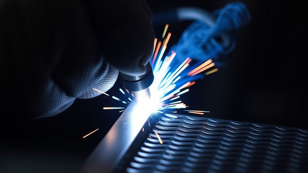
Straight and consistent MIG weld beads come from a repeatable setup, not from copying one voltage and wire-speed combination. Clean the joint, match the wire and shielding gas to the metal, brace your body, hold a stable gun angle and contact-tip-to-work distance, and watch the leading edge of the puddle while you move at an even pace.
Quick Answer
To run a straight MIG bead, clean and clamp the metal, use your welder’s chart for the first settings, brace both hands, and hold a steady 5- to 15-degree travel angle. Keep the contact tip roughly 3/8 to 1/2 inch from the work, watch the puddle’s front edge, and adjust one variable at a time.
Key Takeaways
- Start with the settings chart inside your welder, the owner’s manual, or an approved welding procedure instead of treating one voltage and wire speed as universal.
- Clean metal, a solid work-clamp connection, smooth wire feeding, and stable gas coverage prevent many bead problems before you start.
- Brace your hands and keep work angle, travel angle, contact-tip-to-work distance, and travel speed steady.
- Use straight stringer beads while learning. Add only a small controlled motion when the joint or procedure requires it.
- Judge the bead by tie-in, profile, consistency, and defects, not by appearance alone. Structural work must follow the drawing, code, or WPS.
At a Glance
| Time Required | 20 to 45 minutes for setup and several practice beads |
| Difficulty | Beginner to intermediate |
| Tools Needed | MIG welder, correct wire and gas, PPE, clamps, cleaning tools, scrap metal, soapstone, and weld gauges if required |
| Cost | Low for practice if you already own the welder and safety gear; wire, gas, tips, and scrap are the main consumables |
Warning: MIG welding creates electric-shock, fire, ultraviolet-radiation, hot-metal, gas-cylinder, and fume hazards. Wear a welding helmet with the correct shade, safety glasses, flame-resistant clothing, and welding gloves. Remove or shield combustibles, keep suitable fire-extinguishing equipment ready, and use ventilation that controls fumes without blowing away the shielding gas.
What’s in This Article
- What You Need for Consistent MIG Weld Beads
- Choose Safe Starting Settings
- Prepare Your Welding Workspace
- Run a Straight MIG Weld Bead Step by Step
- Control Gun Angle, Stickout, and Travel Speed
- Practice Drills for Straighter Beads
- Troubleshoot Common MIG Welding Defects
- Reliable MIG Welding Learning Resources
- Frequently Asked Questions
- Conclusion
- Sources
What You Need for Consistent MIG Weld Beads
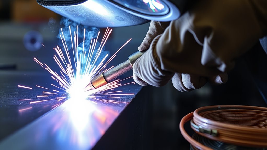
Good beads start before you pull the trigger. You need equipment that matches the material, consumables in good condition, clean base metal, and enough output for the joint you plan to weld.
- MIG welder: Use a machine rated for the material thickness, wire diameter, duty cycle, and input power available.
- Correct filler wire: ER70S-6 is a common solid wire for mild steel. Match the wire classification and diameter to the base metal, machine, and job requirements.
- Correct polarity: Most solid-steel MIG wire runs on direct-current electrode positive, or DCEP. Confirm the wire label and welder manual because some self-shielded flux-cored wires use the opposite polarity.
- Shielding gas: A 75% argon and 25% CO2 mix, often called C25, is a common choice for short-circuit MIG welding on mild steel because it supports a stable arc, good bead shape, and relatively low spatter.
- Consumables: Fit the correct drive-roll groove, liner, contact tip, diffuser, and nozzle for the wire. Replace damaged tips and clear spatter from the nozzle.
- Safety gear: Use a welding helmet, safety glasses, welding gloves, hearing protection where needed, leather footwear, and flame-resistant clothing that covers exposed skin.
- Preparation tools: Keep clamps, a grinder or suitable abrasive, a dedicated wire brush, soapstone, pliers, and clean practice coupons nearby.
For 1/4-inch mild steel, 0.035-inch solid wire can be suitable on many 230-volt machines, but the joint may need beveling, multiple passes, or a larger machine. Do not assume that wire diameter alone proves the weld will have enough fusion or strength.
The most useful starting settings are the ones listed for your exact machine, wire, gas, material thickness, joint, and welding position.
Products Worth Considering

Package Including 10pcs x 0.035" Contact Tip, 2pcs x Gas Nozzle, 2pcs x Gas Diffuser.

COMPATIBILITY: Designed for Lincoln Magnum 100L (K530 series) and Tweco Mini/#1 welding torches. This kit is also a direct fit for YESWELDER FLUX-135PRO Old Version/MIG-140DS PRO/YWM-160/MIG-165DS PRO/MIG-185DS PRO/MIG-205DS PRO/MIG-250PRO/MCT-520.

Package Including 10pcs x 0.030" Contact Tip, 2pcs x Gas Nozzle, 2pcs x Gas Diffuser.
Choose Safe Starting Settings
Voltage, wire feed speed, and travel speed work together. Wire feed speed largely controls amperage in constant-voltage MIG welding, while voltage changes arc length and bead width. Travel speed then controls how much heat and filler metal you place along each inch of the joint.
Use the chart inside the welder’s wire compartment or the owner’s manual first. If you are doing code, structural, pressure, vehicle-frame, lifting, or safety-critical work, follow the approved welding procedure specification and drawing instead of a general online setting.
| Variable | Practical Starting Point for Mild-Steel Practice | What to Verify |
| Wire | 0.030- or 0.035-inch ER70S-6 solid wire | Machine range, base metal, joint, and required filler classification |
| Polarity | DCEP for most solid-steel MIG wires | Wire package and welder manual |
| Shielding gas | 75% argon / 25% CO2 | Wire recommendation and transfer mode |
| Gas flow | About 20 to 30 CFH indoors; 25 CFH is a common test point | Nozzle flow, drafts, leaks, cup size, and manufacturer guidance |
| Contact-tip-to-work distance | Roughly 3/8 to 1/2 inch for common short-circuit steel practice | Transfer mode, wire size, access, and manual |
| Travel angle | About 5 to 15 degrees | Push or drag technique, position, and joint |
The original 21-volt and 375-IPM combination may produce a usable bead on some machines with 0.035-inch wire and C25 gas, but it is not a universal setting for 1/4-inch steel. Treat it only as a scrap-test example when it is close to your machine’s recommended range. If the chart calls for different values, follow the chart.
Note: Do not raise gas flow automatically when you see porosity. Excessive flow can create turbulence and pull air into the shielding envelope. Check for drafts, leaks, a blocked nozzle, an excessive gun distance, and contaminated metal first.
Preparing Your Welding Workspace
A stable workspace makes it easier to keep the gun straight and helps prevent fire, fume, electrical, and quality problems.
- Remove fire hazards: Move paper, fuel, solvents, sawdust, oily rags, and other combustibles away from sparks. Shield anything that cannot be moved and keep suitable extinguishing equipment ready.
- Ventilate the area: Use general ventilation or local fume extraction that pulls fumes away from your breathing zone without drawing the shielding gas off the puddle.
- Identify coatings: Do not weld unknown, painted, plated, galvanized, lead-coated, or solvent-contaminated metal until you understand the hazard and follow the required control method.
- Prepare the material: Remove oil and grease before grinding. Then clean rust, paint, scale, and coating from the weld zone and work-clamp area.
- Secure the work: Clamp the pieces so joint gap and alignment cannot change while you weld.
- Attach the work clamp: Place it on clean metal as close to the weld as practical. Check that cables, connectors, and the gun are tight and undamaged.
- Check the wire path: Confirm the spool brake, drive-roll size, drive-roll tension, liner, contact tip, and polarity. Keep the gun cable as straight as practical during feeding.
- Check gas coverage: Open the cylinder correctly, check the regulator and hoses, set the flow while gas is moving, and clear spatter from the nozzle.
- Set your body position: Dry-run the whole bead with the gun off. Make sure you can reach the end without locking your wrist, lifting your elbow, or losing your view.
Use grinder-rated accessories when you clean or prep your material. Match the wheel to the grinder’s maximum speed and the metal, and keep the guard installed.
Warning: Never weld, cut, or grind a drum, tank, pipe, or closed container that held a flammable or toxic substance unless a qualified procedure has made it safe. Vapors or trapped pressure can cause an explosion or release toxic gases.
Products Worth Considering
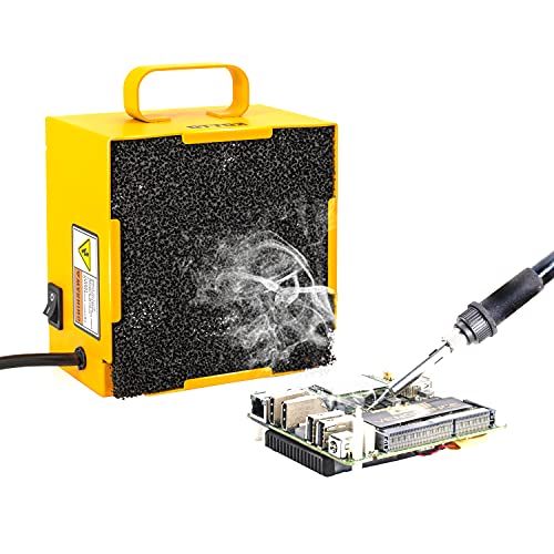
Solder Fume Extractor/Smoke Trap/Smoke Eater/Smoke Filter/Solder Sucker Prevention Absorber DIY Working Extractor Fan for Solder Station.

Powerful & Energy-Efficient: Equipped with a high-performance 585W AC motor, it delivers outstanding ventilation performance, achieving an airflow volume of 3198CFM. Quickly and thoroughly eliminate smoke, odors, and hot air.

Fume-Free Workspace in Minutes: The KQZ B1 Fume Extractor equips a high-efficiency centrifugal motor with 168 m³/h airflow. Strong instant suction captures fumes and fine particles. H13 HEPA filter with coal-based activated carbon delivers full purification for a safer working environment
Step-by-Step Process for Straight MIG Weld Beads
Practice first on flat scrap that matches the type and thickness of your project. Beads on plate are useful for hand control, but joint coupons are better for learning tie-in and work angle.
- Clean the practice area: Expose bright metal where the bead and work clamp will sit.
- Draw a guide line: Mark a straight soapstone line. Place it where you can follow it with the nozzle edge without hiding the puddle.
- Set the machine: Select the wire, gas, polarity, voltage, and wire feed speed from the welder chart or approved procedure.
- Set gas flow: With gas flowing, set the recommended CFH and check the nozzle for blockage.
- Trim the wire: Leave a clean wire end and establish the intended contact-tip-to-work distance.
- Dry-run the path: Move from start to finish with the trigger released. Adjust your feet, chair, cable, and forearm support until the motion feels smooth.
- Use two hands: Hold the gun with your dominant hand and support the neck or dominant wrist with the other hand. Keep fingers away from hot metal.
- Set the angles: Use the correct work angle for the joint and a small 5- to 15-degree travel angle. Avoid leaning the gun excessively.
- Start the puddle: Pull the trigger and let the arc establish. Begin moving as soon as a controllable puddle forms so the start does not pile up.
- Watch the leading edge: Look through the arc at the front and sides of the puddle. Keep the arc near the leading edge instead of chasing the cooling bead behind it.
- Move your forearms, not only your wrist: Let your supported arms slide or pivot smoothly. Keep nozzle distance and angle steady through the full pass.
- Hold a constant pace: Match travel speed to puddle size. Do not speed up because the arc gets brighter or slow down to make the bead look larger.
- Finish the crater: At the end, use the machine’s crater control when available or make a brief controlled pause without creating a large lump. Release the trigger and keep the gun near the weld during post-flow if the machine provides it.
- Let the metal cool safely: Mark hot material and use pliers when needed. Do not touch or quench practice coupons unless the procedure allows it.
- Inspect and record: Note voltage, wire speed, gas flow, wire, joint, position, travel direction, and the defect you are trying to correct.
Pro Tip: Place the guide line beside the joint, not directly under the arc. Follow it with one edge of the nozzle while your eyes stay on the puddle and both toes of the weld.
Mastering MIG Welding Techniques
Four technique variables have the biggest effect on whether your MIG bead stays straight: work angle, travel angle, contact-tip-to-work distance, and travel speed.
Use the Correct Work Angle
Work angle points the wire into the joint. It changes with joint shape, even when your travel direction stays the same.
- Butt joint: Hold the gun close to 90 degrees to the plate so the wire points into the joint.
- T-joint or fillet weld: Start near 45 degrees so the wire divides heat and filler between both pieces.
- Lap joint: Start around 60 to 70 degrees and direct the arc toward the lower edge of the top sheet while still fusing the lower sheet.
Change the angle only when thickness, position, fit-up, or a multi-pass sequence requires it. If one fillet leg becomes much larger, correct the work angle before changing the machine.
Keep the Travel Angle Small
A small travel angle helps the arc stay stable. For common steel MIG work, 5 to 15 degrees is a useful range. Angles beyond roughly 20 to 25 degrees can increase spatter, reduce penetration, and make the arc less stable.
On mild steel, either push or drag may work when the procedure allows it. Pushing usually gives you a clearer view of the joint and a wider, flatter bead. Dragging often makes a narrower bead with more buildup and can increase penetration. Keep the selected direction consistent for the whole practice pass.
Control Contact-Tip-to-Work Distance
Stickout is the wire extending beyond the contact tip. Contact-tip-to-work distance includes that wire plus any recessed tip-to-nozzle distance. Welders often use the terms loosely, so focus on measuring from the contact tip to the work.
For common short-circuit steel practice, roughly 3/8 to 1/2 inch is a useful starting range. Holding the gun too far away can reduce heat at the work, weaken gas coverage, and make the bead wander. Moving too close can cause the tip to contact the puddle or fill with spatter.
Use Travel Speed to Hold Puddle Size
Travel speed should keep the puddle large enough to wet into both sides without becoming difficult to control.
- Too fast: The bead becomes narrow, uneven, or convex and may show poor tie-in or undercut.
- Too slow: The bead becomes too wide or tall, heat input rises, and thin metal may distort or burn through.
- Correct pace: The arc stays near the puddle’s leading edge, the bead width remains steady, and both toes blend into the base metal.
Start With a Stringer Bead
A straight stringer bead is the best motion for learning consistency. Keep the gun steady and move forward without drawing large circles, cursive letters, or exaggerated patterns. A small controlled oscillation can help with a wide joint, gap, or multi-pass weld, but the procedure and joint should decide the motion.
Good ventilation matters for every weld. It matters even more around coated or galvanized metal because heating zinc can create hazardous fumes. Review the precautions for zinc fume exposure, and use the controls required for the workplace and coating.
Practice Drills for Straighter Beads
Random practice can repeat the same mistake. Use short drills that isolate one skill and keep the other variables fixed.
- Dry-motion drill: With the machine off, follow five parallel lines while maintaining the same nozzle height and angle.
- Beads-on-plate drill: Run five 3- to 4-inch stringer beads. Keep the settings unchanged and focus only on spacing, direction, and travel speed.
- Distance drill: Run one bead with your normal distance, one intentionally too long, and one slightly shorter. Compare arc stability and bead shape, then return to the correct range.
- Travel-speed drill: Divide a line into three sections. Travel too fast, then too slow, then at your best pace. Label the coupon after it cools.
- Fillet-joint drill: Tack two coupons into a T-joint and practice maintaining a 45-degree work angle with equal weld legs.
- Restart drill: Practice stopping and restarting on noncritical scrap without leaving a deep crater, cold lap, or oversized lump.
Change only one variable between beads. Record the result so you can separate a machine-setting problem from a hand-control problem.
Note: A smooth-looking practice bead does not prove full fusion. For important work, use the inspection, testing, acceptance criteria, and welder qualification required by the applicable code or procedure.
Troubleshooting Common MIG Welding Defects
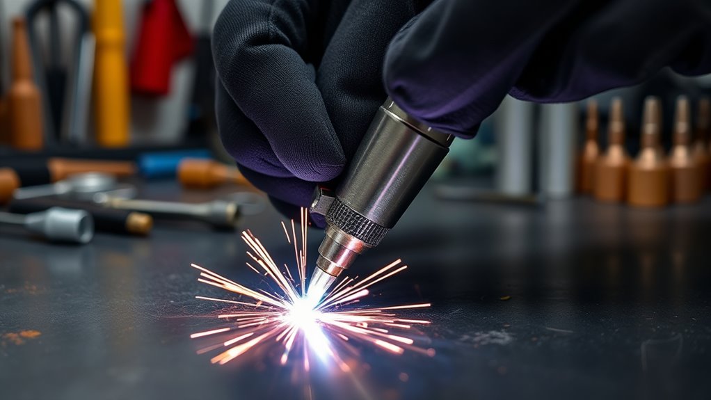
Use the bead shape, arc behavior, and surface condition as clues. One symptom can have several causes, so begin with the simplest checks and change one variable at a time.
| Problem | Likely Causes | Checks and Fixes |
| Wandering bead | Poor body position, unsupported hands, dirty lens, hidden joint, inconsistent distance, or cable drag | Clean the lens, improve lighting, dry-run the path, brace both hands, reposition the cable, and follow a guide beside the joint |
| Tall, narrow, convex bead | Voltage too low, wire feed too low or mismatched, travel too fast, long distance, or poor work angle | Return to the chart, correct distance and angle, then fine-tune voltage and wire speed in small steps |
| Very wide or flat bead | Travel too slow, voltage too high, excessive weaving, or too much heat for the joint | Increase travel speed, reduce unnecessary motion, and compare the voltage with the chart or WPS |
| Porosity | No gas, low or turbulent flow, leaks, drafts, blocked nozzle, long distance, wet wire, paint, oil, rust, or coating | Stop welding, confirm gas at the nozzle, repair leaks, block drafts, clean the nozzle and joint, and replace contaminated consumables |
| Undercut | Excessive voltage, travel too fast, wrong angle, or failing to fill the toes | Correct the work angle, reduce excessive heat, slow slightly if needed, and keep the arc positioned so both toes fill |
| Lack of fusion or poor tie-in | Cold settings, travel too fast, wrong angle, dirty joint, poor preparation, or machine too small | Clean and prepare the joint, correct the angle, use the proper setting or process, and bevel or make multiple passes when the procedure requires it |
| Heavy spatter or erratic arc | Voltage and wire speed mismatch, wrong polarity, poor clamp, worn tip, feed slip, contamination, or excessive gun angle | Verify polarity and chart settings, clean the clamp point, inspect feeding parts, replace the tip, and reduce the angle |
| Start or stop crater | Lingering too long at the start, stopping abruptly, or poor restart placement | Begin moving as the puddle forms, use crater-fill controls when available, and practice restarts on scrap |
Good shielding gas flow reduces porosity only when the gas reaches the weld without leaks, blockage, wind, or turbulence. More CFH is not always better.
Note: Grind out and repair cracks, slag inclusions, or porous sections only under a suitable repair procedure. Do not cover a defect with another pass and assume the joint is sound.
Top Online Resources to Enhance Your MIG Welding Skills
Online learning helps most when it supports structured practice. Start with manufacturer and safety sources, then use videos or classes to see body position and puddle control in real time.
- Welder owner’s manual: Use it for polarity, setup, consumables, input power, duty cycle, and machine-specific settings.
- Wire manufacturer’s data sheet: Check classification, gas, polarity, operating range, storage, and mechanical properties.
- Miller and Lincoln Electric education pages: Use their parameter, technique, and defect guides as general references, then confirm the advice against your own machine.
- OSHA welding resources: Review fire prevention, PPE, ventilation, confined-space, and coating hazards.
- Hands-on instruction: A qualified instructor can see angle, distance, travel speed, and unsafe habits that are difficult to diagnose from a finished bead photo.
Course platforms such as Udemy and Coursera may offer structured lessons, while YouTube channels can show gun movement and puddle behavior. Check the instructor’s qualifications, compare advice with official documentation, and avoid copying settings without matching the material, wire, gas, joint, position, and machine.
Welding forums and community groups can help you compare results. When asking for feedback, include clear photos plus material type and thickness, joint, position, wire classification and diameter, gas mix and flow, polarity, voltage, wire feed speed, and contact-tip-to-work distance.
Before testing a new technique, focus on proper metal preparation. Clean material and a sound setup make feedback easier to trust because they remove several variables.
Frequently Asked Questions
How do you get more consistent MIG welds?
Use the same preparation and setup each time. Clean and clamp the joint, follow the machine chart or WPS, brace both hands, and keep work angle, travel angle, contact-tip-to-work distance, and travel speed steady. Change only one variable between practice beads.
Can you MIG weld in a straight line?
Yes. A straight stringer bead is often the best motion for practice and many joints. Dry-run the path, support your arms, follow a guide beside the joint, and move your forearms smoothly instead of steering only with your wrist.
Should you push or pull a MIG weld?
On mild steel, either may be acceptable when the procedure allows it. Pushing usually improves your view of the joint and makes a wider, flatter bead. Pulling often makes a narrower bead with more buildup and can increase penetration. Aluminum MIG normally requires a push technique.
What is the correct MIG gun angle?
Use a travel angle of about 5 to 15 degrees for common steel work. Set the work angle to the joint: about 90 degrees for a butt joint, 45 degrees for a T-joint, and roughly 60 to 70 degrees for a lap joint. Adjust when the procedure or welding position requires it.
How far should the MIG gun be from the metal?
For common short-circuit steel practice, keep the contact tip roughly 3/8 to 1/2 inch from the work unless your manual or procedure gives another value. Hold the distance steady because moving farther away changes heat, arc behavior, and gas coverage.
How can you improve MIG weld bead appearance?
Clean the metal, stabilize gas coverage, use the correct polarity and consumables, and keep your motion steady. Then compare the bead with the machine chart and adjust voltage, wire feed speed, or travel speed one at a time. Do not trade fusion for a cosmetic bead.
How should a good MIG bead look?
A good bead has consistent width and height, smooth tie-in at both toes, and no visible cracks, porosity, undercut, or unfilled crater. The exact profile and weld size depend on the joint and procedure, so appearance alone cannot prove fusion or strength.
Why does my MIG weld bead wander?
A wandering bead usually comes from poor body position, unsupported hands, an obstructed view, inconsistent contact-tip-to-work distance, or cable drag. Improve lighting, clean the helmet lens, dry-run the path, brace your arms, and use a soapstone guide beside the joint.
Safety Disclaimer: This article provides general educational information and does not replace hands-on training, the welder manual, a job hazard assessment, an engineered weld design, or an approved welding procedure. Follow applicable laws, codes, workplace rules, and manufacturer instructions.
Conclusion
Straight and consistent MIG weld beads come from a controlled process: clean metal, correct consumables, safe starting settings, stable gas coverage, supported hands, steady angles, a fixed contact-tip-to-work distance, and even travel speed.
Use the chart or WPS first, then practice on matching scrap and adjust one variable at a time. Watch the leading edge of the puddle, inspect both toes, and record what changed. With repeatable practice, you will learn to separate setup problems from movement problems and correct the bead faster.
Sources
- Miller, MIG Welding: Setting the Correct Parameters — wire-size ranges, setting relationships, and bead-based adjustment guidance
- Miller, MIG Welding Tips and Techniques for Beginners — hand support, stickout, work angles, travel angle, and travel speed
- Miller, What Type of Gas Is Best for MIG Welding? — C25 gas, flow-rate guidance, gas coverage, and contact-tip-to-work distance
- Miller, Common MIG Weld Defects — porosity, lack of fusion, craters, burn-through, and setting symptoms
- OSHA 29 CFR 1910.252 — fire prevention, PPE, ventilation, coated-metal, and confined-space requirements
- CDC/NIOSH, Welding Fumes and Manganese — welding-fume exposure and confined-space risk information




