
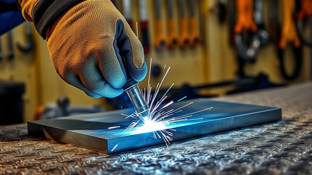
A portable spot welder can join overlapping sheet metal quickly, but the weld is only reliable when the material, machine capacity, electrode force, current, and weld time work together. Start with clean, tightly fitted test coupons, follow the settings in your machine manual, and prove the setup with a destructive test before you weld the finished part.
Quick Answer
To use a spot welder, clean and overlap the sheets, align the electrode tips, set the force and weld schedule from the machine manual, and test the setup on matching scrap. Clamp the sheets between the electrodes, complete the weld cycle without moving the joint, then inspect and peel-test the scrap coupon before welding the final part.
Key Takeaways
- Use the settings and combined-thickness limit listed for your exact spot welder, tongs, electrodes, and material.
- Make the sheets fit tightly before applying electrode force. Do not use the tongs to pull a gap closed.
- Keep your hands out from between the tips and protect yourself from sparks, hot metal, fumes, and electrical hazards.
- Test on scrap that matches the final sheet thickness, coating, overlap, and material.
- Use a destructive peel test on the scrap coupon to validate the weld instead of relying on appearance alone.
- Stop and correct the setup if you see expulsion, burn-through, off-center marks, overheated tips, or changing weld quality.
At a Glance
| Time Required | About 15 to 30 minutes for cleaning, setup, test welds, adjustment, and a small finished joint |
| Difficulty | Beginner to intermediate, depending on the material and required joint strength |
| Tools Needed | Suitable spot welder, correct electrodes, clamps, approved cleaner, test coupons, eye and face protection, insulated gloves, and fire-resistant clothing |
| Cost | Varies by machine and material; resistance spot welding normally uses no filler wire or shielding gas |
What’s in This Article
- Understand the Basics of Spot Welding
- Know Your Machine’s Limits
- Essential Tools and Safety Gear
- What You’ll Need Before You Start
- Prepare the Metal Pieces for Welding
- Plan the Joint and Weld Locations
- Get Your Spot Welder Ready
- Choose Pressure, Current, and Weld Time
- Complete the Spot-Welding Process
- Inspect and Test the Weld
- Spot-Welding Troubleshooting Tips
- Frequently Asked Questions
- Conclusion
- Sources
Understand the Basics of Spot Welding
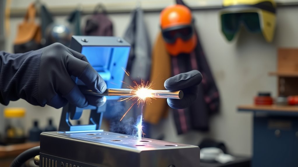
Spot welding, also called resistance spot welding, joins overlapping sheets at separate contact points. It does not use filler wire. Instead, shaped copper-alloy electrodes press the sheets together and carry a high electrical current through the joint.
Electrical resistance creates concentrated heat where the sheets touch. A small molten zone forms between the sheets. The current then stops while electrode force remains in place, allowing the molten area to solidify into a weld nugget. The TWI explanation of resistance spot welding illustrates this process.
A sound spot weld depends on the combined effect of current, electrical resistance, electrode force, and current-on time. Changing one variable can change the result of the others.
A controlled spot-welding cycle may include four stages:
- Squeeze time: The electrodes close and establish the required force before current begins.
- Weld time: Current passes through the joint and forms the molten nugget.
- Hold time: Current stops, but the electrodes remain closed while the nugget solidifies.
- Off or recovery time: The machine rests before the next cycle, where applicable.
Manual tong welders may not let you adjust every stage separately. Follow the controls and sequence described in your machine manual rather than assuming that every spot welder operates the same way.
Note: This guide focuses on tong-style resistance spot welders used for overlapping sheet metal. Battery-tab welders, stud welders, dent-repair machines, robotic cells, and projection welders use different controls and safety procedures.
Know Your Machine’s Limits
Do not choose a spot welder or weld schedule from sheet thickness alone. Check all of these limits in the manual:
- Combined material thickness: A capacity rating may refer to both overlapping sheets together, not the thickness of each sheet.
- Material: A machine rated for uncoated low-carbon steel may not be suitable for aluminum, copper, hardened steel, or every coated steel.
- Tong length: Longer tongs can reduce available welding current on some portable machines.
- Electrode style and face diameter: The installed tips must match the machine and application.
- Input power: The outlet, circuit, plug, and protection must match the nameplate and manual.
- Duty cycle: The welder needs recovery time to avoid overheating.
The capacity listed for one model does not create a universal limit for all spot welders. The Miller MSW-series manual, for example, lists different combined-thickness capacities for different portable models and instructs users to respect the machine’s rated duty cycle.
Warning: Do not spot-weld a structural vehicle part, airbag-area component, fuel-system component, closed container, pressure vessel, or unknown material from general internet instructions. Use the vehicle or equipment maker’s repair procedure and qualified help where the joint affects safety.
Essential Tools and Safety Gear
Spot welding has no exposed arc like MIG or stick welding, but it can still eject sparks and molten metal. The electrode tongs also create a serious pinch point.
Wear the protection specified by the manufacturer. For a typical portable tong welder, this includes:
- Approved safety glasses or goggles with side protection
- A face shield when sparks or metal expulsion may occur
- Dry, hole-free, heat-resistant welding gloves
- Flame-resistant long sleeves or a welding jacket
- Cuffless trousers and closed, high-top work shoes
- Hearing protection when required by the work environment
Keep other people away from the work or protect them with suitable fire-resistant screens. OSHA’s resistance-welding requirements address guarding, flying-spark shields, switch protection, and machine grounding in covered workplaces.
Warning: Never place a finger, hand, loose sleeve, cable, or tool between the electrode tips. Keep clear of the tongs, lever, linkage, and every moving pinch point before applying pressure or power.
Remove paper, oily rags, aerosol cans, fuel, solvents, sawdust, and other combustibles from the area. Keep a suitable fire extinguisher nearby and inspect both sides of the work after welding because hot metal and sparks can reach hidden areas.
Use the welder only in a dry location. Connect it to the voltage, circuit, and grounded receptacle required by its manual. Do not remove the grounding pin, use a damaged extension cord, or operate a unit with cracked insulation, loose plugs, exposed conductors, or missing guards.
A tong-style resistance spot welder normally does not use a separate work-ground clamp. “Grounding” refers to the machine’s approved equipment-grounding system and electrical installation.
Strong electromagnetic fields may affect pacemakers and other implanted medical devices. Anyone with such a device should follow medical and equipment-manufacturer guidance before approaching resistance-welding work.
Products Worth Considering

EYE & FACE PROTECTION - Jackson Safety’s GPL550 Safety Goggles with a detachable flip-up face shield ensure your safety in the most demanding environments with indirect vents and anti-fog coating

Soft Material: The items are made of flexible TPU polyurethane which is friendly to humans.They will provide the softest care for your eyes.

SUPERIOR PROTECTION — Experience all-around face protection thanks to the curved design of this faceshield. The visor of this face guard is ANSI Z87+ certified, and up to 2x thicker for increased durability. Plus, you can comfortably wear your grinding face shield over prescription glasses.
What You’ll Need Before You Start
- Spot welder rated for the material and combined sheet thickness
- Correct tongs and electrode tips
- Representative scrap coupons matching the finished material
- Clamps or locking pliers that will not obstruct the electrodes
- Approved, nonflammable metal cleaner or degreaser
- Clean lint-free cloths
- Abrasive pad or other preparation tool approved for the material
- Safety glasses or goggles with side protection
- Face shield where sparks or expulsion may occur
- Dry insulated gloves and flame-resistant clothing
- Bench vise and suitable hand tools for destructive coupon testing
- Fire extinguisher suitable for the work area
- The exact machine manual and material safety information
Use scrap from the same material batch when possible. Match the sheet thickness, coating, overlap, number of layers, and surface preparation used on the final joint. A test made on clean bare mild steel does not validate a setting for coated, hardened, stainless, or unequal-thickness material.
Products Worth Considering

Material: Aluminum oxide copper

2 Pair of 1/8" Contact Tips w/ M8-1.25 Metric Thread

Quantity: 10Pcs , Copper Welding Pin Soldering Needle for Spot Welder Machine
Prepare the Metal Pieces for Welding
Unplug or isolate the welder before cleaning, installing, aligning, or dressing the electrodes. Let hot tongs and tips cool before touching them.
Inspect the sheets for oil, paint, rust, scale, adhesive, sealer, plating, and unknown residue. Clean both sides around each planned weld so the electrodes make consistent contact. Heavily oiled sheet should be degreased with a product approved for welding preparation, then allowed to dry fully.
Do not use a chlorinated cleaner or weld near active degreasing and spraying operations. Heat can react with some vapors and produce highly toxic gases. Read the cleaner’s Safety Data Sheet before use.
Warning: Paint, galvanizing, cadmium, lead, sealers, and other coatings can release hazardous fumes or contaminate the weld. Identify the coating, review its SDS and repair procedure, remove only what the approved procedure requires, and use effective local exhaust. Respiratory protection must be selected through a proper hazard assessment, not guessed.
OSHA recommends cleaning welding surfaces of coatings that could create toxic exposure and placing local exhaust close to the fume source. Its welding-fume fact sheet also warns that an open door or outdoor location does not automatically provide adequate ventilation. Heating galvanized material can expose a worker to zinc oxide fume, which is associated with metal fume fever.
Inspect the electrode tips after cleaning the sheets. The faces should be aligned, clean, and shaped to the dimensions specified by the manufacturer. Dress or replace mushroomed, pitted, contaminated, cracked, or badly worn tips. Do not grind them to an arbitrary shape.
Plan the Joint and Weld Locations
Spot welding normally requires a lap joint because both electrodes must reach opposite sides of the sheets. Mark the approved weld locations before placing the part in the tongs.
The overlap, edge distance, weld spacing, and number of spots depend on the material, sheet thickness, load, electrode size, and applicable repair or engineering procedure. Do not invent a weld count for a structural joint.
Bring the sheets into close contact with ordinary clamps before using the welder. The electrodes supply welding force; they should not be used to pull a large gap closed. Poor fit can produce arcing, expulsion, inconsistent resistance, or a small nugget.
Keep temporary clamps clear of the electrode path. Also consider current shunting: a nearby completed weld or conductive fixture can divert part of the current away from the next location. Follow the specified weld sequence and spacing rather than placing spots randomly.
Pro Tip: Mark the first coupon with the machine setting and preparation method. When you find a successful setup, keep the tested coupon as a reference for the rest of that job.
Get Your Spot Welder Ready
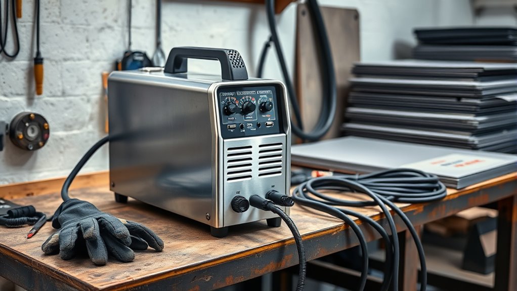
Set up the welder only after the work area, joint, electrodes, and test coupons are ready. This reduces the chance that you will reach around energized equipment or handle hot material unnecessarily.
Complete the Pre-Weld Safety Check
- Remove combustibles and check both sides of the planned weld area.
- Confirm that ventilation or local exhaust is suitable for the material and coating.
- Put on approved eye, face, hand, body, and foot protection.
- Inspect the power cord, plug, grounding pin, controls, tongs, guards, and electrode insulation.
- Verify that the outlet and circuit match the nameplate and manual.
- Keep bystanders outside the spark and pinch-point area.
- Confirm that no fuel vapor, flammable dust, or explosive atmosphere is present.
- Place the fire extinguisher where you can reach it without crossing the hot-work area.
For vehicle work, follow the vehicle maker’s body-repair procedure before connecting the welder. Isolate batteries and sensitive electronics exactly as directed, inspect for fuel lines and hidden trim, and keep welding current away from modules, wiring, airbags, and bearing paths.
Arrange the Tools
Place the test coupons, clamps, cleaner, inspection light, and peel-test tools within easy reach but outside the tong and spark path. Keep clean and contaminated cloths separate.
Support a heavy portable gun or transformer so it cannot fall, twist the joint, or strain its power cable. Do not balance a hot welder on the workpiece.
Check the Equipment
- With power disconnected, confirm that both electrode tips are secure and meet face-to-face.
- Check that the tips close squarely rather than touching at one edge.
- Inspect water hoses and coolant flow if the machine is water-cooled.
- Confirm that the lever, trigger, foot control, timer, and guards operate normally.
- Make sure the machine has not exceeded its inspection or maintenance interval.
- Connect the welder only after the mechanical checks are complete.
Stop if the circuit trips, the plug or cord becomes hot, the transformer smells overheated, coolant leaks, or a control sticks. Disconnect power and have the problem corrected before welding again.
Choose Pressure, Current, and Weld Time
Use the starting schedule in the exact machine manual or approved repair procedure. Do not copy a setting from a different machine merely because the sheet thickness looks similar.
The three main variables are connected:
- Electrode force: Holds the sheets and tips in consistent contact before, during, and after current flow.
- Welding current: Strongly affects how quickly heat develops at the sheet interface.
- Weld time: Controls how long current contributes heat to the joint.
Some portable welders provide only a timer, while others also allow current or force adjustment. A timer marked from 0 to 5 seconds does not mean that 3 to 5 seconds is correct for every weld. Use the manufacturer’s starting point and verify it on a coupon.
| Variable | When It Is Too Low | When It Is Too High |
|---|---|---|
| Current or heat input | Small nugget, weak peel test, little or no button pullout | Expulsion, burn-through, deep indentation, rapid tip damage |
| Weld time | Incomplete nugget growth or an easily separated coupon | Excessive heating, distortion, expulsion, or overheated electrodes |
| Electrode force | Arcing, poor contact, expulsion, or unstable results | Excessive indentation or insufficient interface heating for the selected schedule |
Make one test weld, let the machine complete its full cycle, and inspect the coupon. Change one adjustable variable at a time so you know what caused the result. Repeat until the coupon passes the required test without excessive expulsion or indentation.
Complete the Spot-Welding Process
- Position the sheets: Place the tightly fitted lap joint between the electrode tips at the first marked location.
- Support the work: Hold or fixture the sheets so their weight will not pull the joint apart or twist the tongs.
- Check the electrode path: Confirm that no finger, clamp, cable, trim, or hidden component is between or near the tips.
- Apply electrode force: Close the tongs fully so the tips contact the sheets squarely.
- Start the weld cycle: Activate the trigger, switch, or foot control exactly as described in the manual.
- Keep the joint still: Do not release pressure or move the work while current is flowing.
- Complete the hold stage: Keep the electrodes closed until the machine’s cycle ends or the manual directs you to release them.
- Open the tongs: Remove the work without touching the hot weld or electrode faces.
- Inspect the spot: Check for expulsion, off-center impressions, cracks, holes, severe indentation, or visible separation.
- Continue in the approved sequence: Make the remaining spots while respecting weld spacing, machine duty cycle, and changing tip condition.
Do not automatically increase time when a weld is weak. First check surface cleanliness, sheet fit, tip alignment, tong pressure, line voltage, machine capacity, and electrode condition. A longer cycle can overheat the tips without correcting the real cause.
Follow the duty cycle on the machine nameplate or manual. If the unit overheats or its thermal protection activates, stop and allow the specified recovery period. Do not bypass fuses, breakers, thermal protection, or safety controls.
Inspect and Test the Weld
Visual inspection can reveal surface problems, but it cannot prove that the hidden nugget has the required size or strength. Validate the setup with the test method required by the job.
Visual Inspection
Look at both electrode impressions and check for:
- Centered, reasonably even marks on both sides
- No burn-through or open hole
- No crack or visible separation between the sheets
- No severe dishing or crushing
- No heavy expulsion or metal stuck to the tips
- Consistent appearance from one spot to the next
An off-center or crescent-shaped mark often points to misaligned tips. A deep indentation can indicate excessive heat, excessive force, a damaged tip face, or a schedule that does not suit the material.
Destructive Peel Test on Scrap
- Make one or more welds on a coupon prepared exactly like the final joint.
- Secure one end of the coupon in a vise.
- Peel or twist the sheets apart with a suitable tool while wearing eye and hand protection.
- Inspect the failure. A useful result normally pulls a distinct metal button from one sheet instead of separating cleanly at the original interface.
- Measure or evaluate the button and failure mode against the machine, repair, engineering, or quality requirement.
Warning: A peel test destroys the sample. Perform it on representative scrap or a designated qualification coupon, not on a finished safety-critical joint unless the approved procedure specifically requires it.
Pro Tip: Compare later coupons with the first approved test. A gradual change in button size or surface marking can reveal tip wear or contamination before the finished welds fail.
Spot-Welding Troubleshooting Tips
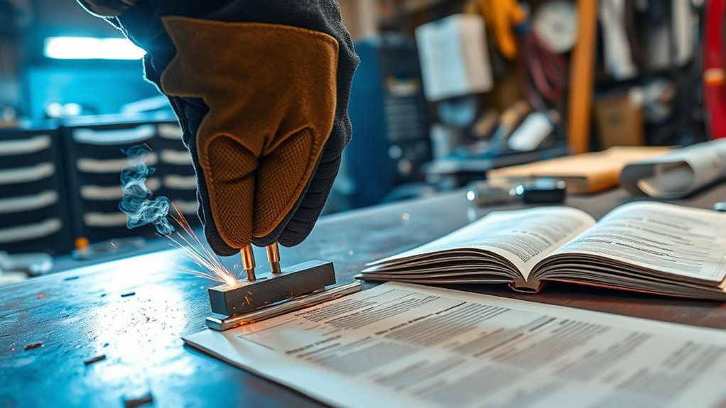
Begin with the simplest causes: dirty material, loose fit, worn tips, poor alignment, incorrect force, an unsuitable schedule, or material beyond the machine’s capacity. Disconnect input power before cleaning, aligning, dressing, or replacing electrodes.
| Issue | Likely Causes | What to Check |
|---|---|---|
| Weak weld or no pulled button | Dirty interface, low heat input, poor fit, insufficient force, worn tips, low line voltage, excessive tong reach, or material beyond capacity | Clean and refit the coupon, inspect the tips, verify input power and capacity, then adjust the approved schedule one step at a time |
| Expulsion or heavy sparks | Too much current or time, poor fit, low force, misaligned tips, surface contamination, or excessive force for the selected schedule | Stop, inspect both sides, correct fit and alignment, and return to the manual’s starting schedule |
| Burn-through or hole | Excessive heat, damaged or undersized tip face, wrong material setting, or sheet below the machine’s usable range | Reduce heat only after checking tip condition, force, material, and the approved procedure |
| Off-center or uneven impression | Tips do not meet squarely, work moved, tongs are bent, or the joint is poorly supported | Disconnect power, realign the tips, support the work, and repeat the coupon test |
| Tips overheat or stick | Low force, long weld time, contamination, wrong tip face, excessive duty cycle, or inadequate cooling | Let the machine cool, inspect cooling flow where fitted, dress or replace tips, and correct the schedule |
| Results change after several welds | Tip pickup, mushrooming, overheating, shunting, inconsistent overlap, or changing coating thickness | Compare with the approved coupon, inspect the tips, confirm spacing and fit, and repeat a destructive test |
| Welder trips protection or loses output | Wrong circuit, overheated machine, damaged cable, loose connection, or internal fault | Disconnect the unit and follow the electrical troubleshooting section of the manual; do not bypass protection |
Frequently Asked Questions
How do you operate a spot welder?
Prepare a representative lap-joint coupon, clean the contact areas, align the electrodes, and select the manufacturer’s starting schedule. Apply electrode force, trigger the complete weld cycle without moving the work, and validate the setup with visual inspection and a destructive coupon test before welding the finished part.
What are the basics of spot welding?
Resistance spot welding presses overlapping sheets between copper-alloy electrodes and passes a high current through the joint. Resistance creates heat at the sheet interface, forming a molten nugget that solidifies while electrode force remains applied.
What do F1, F2, F3, and F4 mean on a spot welder?
F1, F2, F3, and F4 have no universal meaning across spot welders. They may identify stored programs, controller functions, pulse stages, or fault codes on a particular machine. Check the manual for the exact model before changing any of them.
What is the correct sequence for spot welding?
Clean and fit the sheets, mark the weld locations, clamp the joint, confirm the electrodes and settings, apply force, run the weld cycle, maintain force through the hold stage, release the work, inspect the spot, and continue in the approved weld sequence.
How long should you hold a spot welder?
There is no universal number of seconds. Use the current-on time and hold sequence specified for your machine, material, combined thickness, electrodes, and force. Test the setting on matching scrap and stop increasing time if you see expulsion, burn-through, deep indentation, or overheated tips.
Why do my spot welds break?
Common causes include dirty contact surfaces, loose fit, insufficient heat input, incorrect electrode force, worn or misaligned tips, current shunting, unsuitable material, or sheets beyond the welder’s capacity. Correct the setup and repeat a destructive test on a representative coupon.
Can you spot-weld galvanized steel?
Some equipment and approved procedures can spot-weld galvanized steel, but the coating changes electrical contact, shortens electrode life, and can produce hazardous zinc-containing fumes. Follow the machine and repair procedure, use suitable ventilation, and restore corrosion protection as specified after welding.
Does a spot welder need a ground clamp on the workpiece?
A typical tong-style resistance spot welder does not use a separate arc-welding work clamp. Its two electrodes complete the secondary welding circuit through the sheets. The machine must still be connected and equipment-grounded exactly as its electrical instructions require.
Safety Disclaimer: This article provides general information and does not replace the equipment manual, an engineered weld schedule, a vehicle-maker repair procedure, workplace rules, or professional training. Resistance spot welders use high current and strong clamping force. Obtain qualified help whenever the material, electrical supply, coating, joint strength, or repair procedure is uncertain.
Conclusion
Good spot welding starts before current flows. Confirm the machine’s capacity, prepare a tight lap joint, align clean electrodes, protect yourself from pinch points and sparks, and begin with the manufacturer’s schedule.
Prove the setup on matching scrap instead of relying on a generic time setting or surface appearance. Once the coupon produces the required failure pattern without burn-through or heavy expulsion, make the finished welds in the approved sequence while watching tip condition and duty cycle.
Sources
- TWI: What Is Spot Welding? — explains electrode pressure, electrical-resistance heating, nugget formation, and the basic process.
- Miller Resistance Spot Welding Handbook — covers heat, time, pressure, surface condition, electrode care, and destructive testing.
- Miller MSW-41/MSW-41T/LMSW-52 Manual — supports portable-welder safety, electrical grounding, duty-cycle, capacity, tip maintenance, controls, and troubleshooting.
- OSHA 29 CFR 1910.255: Resistance Welding — covers guarding, spark shields, protected controls, and equipment grounding in applicable workplaces.
- OSHA: Controlling Hazardous Fume and Gases During Welding — supports coating removal, ventilation, local exhaust, and respiratory-protection precautions.
- CDC: Metal Fume Fever — supports the warning about zinc oxide fume from heated galvanized material.




