
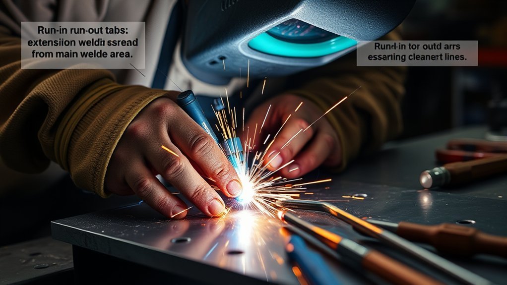
Run-in and run-out tabs give your arc a temporary place to start and finish beyond the edges of the final joint. When the tabs match the workpiece and continue the same joint geometry, they help you establish the puddle before entering the weld and carry the end crater away from the finished part.
Quick Answer
Fit compatible metal tabs at both ends of the joint, continue the groove or corner profile through them, and tack them outside the finished weld area. Start on the run-in tab, weld across the joint without pausing at the edge, finish and fill the crater on the run-out tab, then remove and blend the tabs after cooling.
Key Takeaways
- Run-in tabs move the unstable arc-start area away from the finished joint.
- Run-out tabs let you complete and fill the end crater beyond the finished part.
- Match the tab’s weldability and thickness to the workpiece, and continue the same root opening, bevel, backing, or fillet geometry.
- There is no universal 2- or 3-inch tab rule; size each tab for the process, joint, and approved welding procedure.
- Remove tabs without tearing or gouging the base metal, then inspect the start and stop areas closely.
At a Glance
| Time Required | Usually 15 to 45 extra minutes for a small shop joint; thick, multi-pass, or inspected work can take longer. |
| Difficulty | Beginner to intermediate for practice work; follow the drawing, WPS, and applicable code for structural or safety-critical welds. |
| Tools Needed | Welder, compatible tab stock, clamps or fixtures, cleaning tools, cut-off or removal tool, grinder, inspection light, and process-appropriate PPE. |
| Cost | Usually low when suitable, traceable scrap is allowed; critical work may require specified tab material and documented removal. |
Understanding Run-In and Run-Out Tabs for Welding
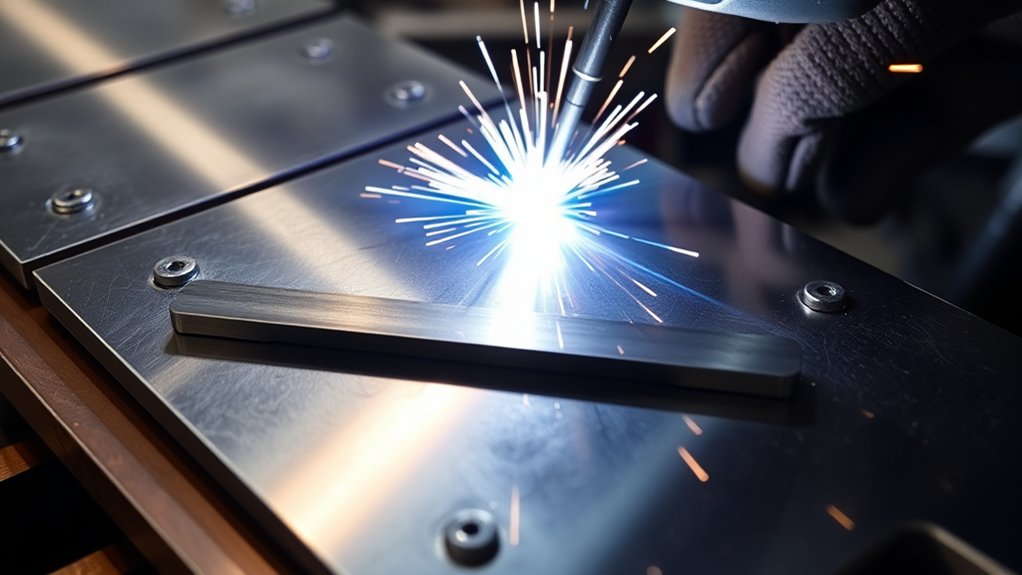
Run-in and run-out tabs are temporary extensions attached at the ends of a weld joint. A run-in tab gives you room to strike the arc, establish shielding and puddle control, reach the intended bead size, and settle into a steady travel speed before the weld enters the finished part.
A run-out tab, also called a runoff tab, gives you room to continue beyond the opposite edge. Instead of stopping on the workpiece, you complete the bead and fill the crater on the temporary extension. This is useful because an abruptly terminated crater can become a weak, crack-prone area, especially in aluminum and other crack-sensitive applications. Miller recommends continuing filler while reducing current or using crater control to prevent TIG crater cracking. See Miller’s TIG crater guidance.
Tabs can also help prevent edge-related cold lap or incomplete fusion in some applications. Lincoln Electric specifically lists run-on and run-off tabs as one possible remedy when cold lapping occurs during aluminum welding. See Lincoln Electric’s aluminum welding guide.
Not every weld needs tabs. They offer the most value on groove welds, test coupons, mechanized seams, open-root practice, plate edges, and joints where full-size weld metal must continue through the end of the required weld. They may add unnecessary work to short, noncritical, intermittent, or hidden welds when the approved procedure uses another sound start-and-stop method.
Good tabs do more than add scrap to each end. They continue the weld path so the puddle crosses onto and off the workpiece without a sudden change in root opening, bevel angle, backing support, corner shape, or heat flow. Clean metal preparation remains essential because tabs cannot correct contamination, poor shielding, or a badly fitted joint.
Note: You may hear these pieces called run-on plates, run-off plates, weld tabs, runoff tabs, lead-on tabs, lead-off tabs, or start-and-stop extensions. The drawing, welding procedure specification, or governing code controls the required design and terminology for inspected work.
A weld tab is successful when the unstable start and stop remain on the temporary metal, while the required joint begins and ends with a sound, full-size weld profile.
When You Should Use Run-In and Run-Out Tabs
Use tabs when the weld start or termination must maintain the required contour, fusion, and size at the edge of the finished joint. They are especially useful when the ends will be inspected, loaded, machined, or exposed.
- Groove welds: Tabs can carry the root, fill, and cap beyond the plate edge so the required joint is not used as the arc-start or arc-stop zone.
- Open-root practice and qualification coupons: A run-in area gives you room to establish the keyhole or puddle before entering the test section.
- Submerged arc and mechanized welding: Extensions provide room for the process to stabilize before and after the production seam.
- Aluminum welds: Tabs can help with cold starts and allow the final crater to be completed beyond the part.
- Visible fillet or edge welds: Tabs may reduce oversized starts, underfilled stops, and abrupt end profiles when the joint arrangement permits them.
- Critical repairs: A qualified procedure may use tabs to keep arc starts, stops, and repair tie-ins away from a highly stressed location.
Do not assume tabs are automatically permitted or required. On structural, pressure, bridge, aerospace, vehicle, lifting, or other regulated work, follow the fabrication drawing, WPS, engineer’s instructions, and applicable code. The approved procedure may specify tab shape, material, tack location, removal method, inspection, and final contour.
Essential Materials for Successful Tab Welding
Products Worth Considering

Enhanced Strength and Durability: These steel tabs offer increased structural strength and durability. Welding table accessories facilitate the even distribution of load, which mitigates stress concentration and potential failure points. Once properly welded, these light tabs become an integral part of the structure, necessitating minimal maintenance while providing enduring reinforcement and reducing the likelihood of structural failure.

🚗【High quality materials】Made of 1/8-inch thick high-quality steel, these trick tabs offer superior strength and durability, making them ideal for a variety of welding projects.
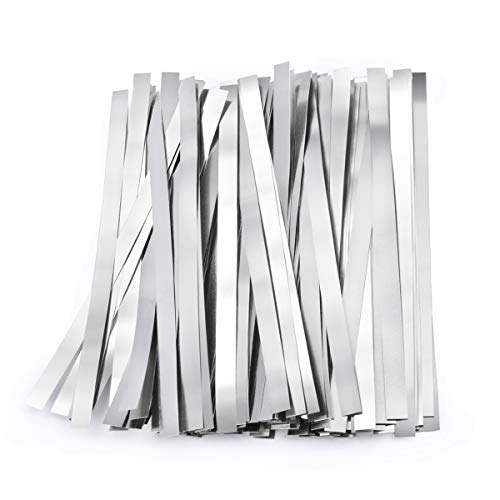
99.6% PURITY: 99.6% pure nickel strip is the material you want, the nickel strip here will never corrode and come loose after welded to a 18650 cell, lithium ion batteries, and any other circuit systems. Nickel strip is commonly used in battery building due to its ease of use in spot welding and soldering as well its high corrosion resistance over time. Nickel is magnetic at or near room temperature.
Match the Tab to the Workpiece
Choose tab stock with compatible weldability and similar thermal behavior. For ordinary mild-steel shop work, clean mild-steel scrap of similar thickness is often suitable. Stainless, aluminum, high-strength steel, and code work need more care because an unknown or incompatible alloy can affect fusion, cracking risk, contamination, and traceability.
Match thickness as closely as practical. A much thinner tab may overheat or burn away before the puddle stabilizes. A much thicker tab can act as a heat sink and make the transition onto the workpiece feel colder. When the WPS or drawing names a material or thickness, use that requirement instead of a general shop rule.
Continue the Joint Geometry
The tab should act like an extension of the joint. Continue the groove angle, root face, root opening, backing arrangement, and alignment into the tab area. For a fillet weld, continue the same corner, tee, or lap geometry so your work angle does not change at the workpiece edge.
A rectangular tab is adequate for many plate joints, but shape alone is not the deciding factor. The tab must support the intended bead width, allow access for the torch or electrode, and remain rigid enough that the groove or root gap does not close during welding.
Size Tabs for the Process, Not a Fixed Rule
There is no universal rule that every run-in or run-out tab must be 2 or 3 inches long. The correct length depends on process startup, material thickness, joint design, position, number of passes, preheat, travel speed, automation, and the governing procedure.
- Length: Provide enough distance to establish the required puddle and bead profile before entering the workpiece, and enough runoff to complete the weld beyond it.
- Width: Support the entire groove or fillet zone without forcing the puddle over an unsupported edge.
- Thickness: Match the workpiece or the WPS closely enough to avoid a sharp change in heat behavior.
- Fit-up: Continue the designed root opening and backing condition. Do not hide an oversized gap with a tab.
- Access: Leave enough room for the gun, torch, electrode, slag removal, interpass cleaning, and inspection.
Keep arc length and the other welding variables consistent as the puddle crosses between the tab and workpiece.
Pro Tip: Make a dry travel pass before welding. Move the torch, gun, or electrode holder from the run-in tab to the run-out tab and check that clamps, tacks, cables, and joint edges will not force an angle or speed change.
Before You Begin: Check the Procedure and Joint
Before cutting tabs, confirm what the job actually requires. For practice pieces, you can choose a sensible tab design based on the joint and process. For production work, review the drawing and WPS before changing the joint or attaching temporary material.
- Confirm the joint details: Check bevel angle, root face, root gap, backing, weld size, position, and required final contour.
- Check tab requirements: Verify the specified material, dimensions, attachment, preheat, removal, and inspection method.
- Inspect the tab stock: Do not use painted, galvanized, oily, cracked, heavily pitted, or unidentified metal on critical work.
- Prepare the work area: Remove combustible material, position screens, arrange ventilation, and keep an extinguisher available where required.
- Plan removal: Leave access for cutting and grinding without striking the finished weld or thinning the base metal.
Warning: Tabs add welding, cutting, and grinding hazards. OSHA requires suitable eye and face protection for arc welding and for flying-particle hazards, plus fire precautions around sparks and hot work. Use the machine guard, safety glasses with side protection, a face shield for grinding, flame-resistant clothing, gloves, hearing protection, and effective fume control.
How to Size and Position Welding Tabs
Position each tab so the weld path remains straight and fully supported. A tab that sits high, low, twisted, or offset can change the work angle and produce undercut, overlap, incomplete fusion, or an irregular cap at the plate edge.
- Extend the joint centerline: Mark the weld path across both tabs before tacking.
- Match the edge preparation: Reproduce the groove, corner, lap, or tee arrangement on the temporary pieces.
- Maintain the root opening: Use spacers or fixtures when needed, then verify the gap after tacking.
- Keep surfaces flush: Align the top and root surfaces so the puddle does not climb or drop at the transition.
- Place tacks outside the required weld: Keep attachment tacks from blocking the groove or becoming trapped in the finished joint.
- Control distortion: Use balanced tacks and a rigid fixture, but do not over-restrain thin material.
For multi-pass groove welds, make sure the tab remains wide and long enough for every pass, not just the root. The fill and cap should also continue beyond the finished joint unless the WPS states otherwise.
Products Worth Considering

Abundant Quantity: you will get 30 pieces of steel weld tabs, the quantity is enough to meet your daily needs and replacements, and you can also share with your family and friends to increase their productivity

Welding Brackets: Crafted from 1/8-inch thick solid steel with rust-resistant treatment, our heavy-duty welding brackets ensure lasting durability and strong support; They withstand high pressure and tension, providing reliable reinforcement for diverse projects

Multi-Purpose: These flat bottom weld on iron tabs can be weld on beams, columns and joints, such as the AC compressors, roof rack, trailer tractor bases, etc. Also can be used for shock absorption of light strips, frames, and suspensions in daily life
Step-by-Step Guide to Attaching and Welding Tabs
- Clean the workpiece and tabs: Remove rust, scale, paint, oil, moisture, and cutting residue from the weld zone and the attachment points.
- Cut compatible tabs: Use the specified material or suitable clean stock with similar thickness and weldability.
- Reproduce the joint: Continue the bevel, root opening, backing, or fillet geometry into the run-in and run-out areas.
- Clamp the full assembly: Support the workpiece and tabs so they cannot sag, twist, or close the root gap.
- Tack the tabs securely: Place small, sound tacks where they will not interfere with the production weld or final inspection zone.
- Recheck fit-up: Measure alignment, root opening, bevel continuity, and access after tacking.
- Set the welding variables: Use the WPS or proven settings for the base material, filler, position, and process.
- Start on the run-in tab: Establish the arc, shielding, puddle, and intended bead profile before entering the finished joint.
- Cross the first edge smoothly: Hold travel speed, arc length, work angle, and travel angle steady. Do not pause on the edge.
- Complete the joint: Watch both puddle toes and maintain the required penetration, fill, and bead size.
- Continue onto the run-out tab: Carry the weld completely beyond the finished joint.
- Fill the crater: Use the approved technique or machine crater function, then end the arc on the temporary tab.
- Clean between passes: Remove slag, oxide, and defects before placing the next bead on multi-pass work.
- Allow controlled cooling: Follow the WPS for interpass and cooling limits. Do not quench unless the procedure specifically permits it.
- Remove and blend the tabs: Use a controlled cut and final grinding step rather than forcing the tab away from the part.
- Inspect the finished joint: Check the weld ends, toes, root, and blended edges before coating or placing the part in service.
Keep the required weld size in mind throughout the transition. A tab does not correct an undersized or oversized bead, so confirm the specified profile and, where relevant, the maximum fillet weld size.
Welding Technique Tips for Cleaner Tab Transitions
MIG and Flux-Core
- Establish stable wire feeding and shielding before the puddle reaches the workpiece.
- Keep contact-tip-to-work distance and gun angle steady across the tab edge.
- Do not accelerate at the edge to escape a growing puddle; correct voltage, wire feed speed, or travel speed before the production weld.
- For flux-core, remove slag completely between passes and from the tab-to-workpiece transition.
Stick Welding
- Start far enough onto the run-in tab to establish a stable arc and full-size bead.
- Keep arc length short and consistent as you cross the edge.
- Plan electrode changes so you do not create an unnecessary stop at the workpiece edge.
- Clean every restart and fill the final crater on the run-out tab.
TIG Welding
- Establish shielding and a controlled puddle on the run-in tab before adding speed.
- Feed filler consistently through the transition so the bead does not become concave or underfilled.
- At the end, continue adding filler while tapering current or use the machine’s crater-control function.
- Maintain post-flow over the hot crater and electrode for the time recommended by the machine or procedure.
Submerged Arc and Mechanized Welding
- Make the tabs long enough for process startup, travel stabilization, and the complete weld sequence.
- Continue backing, flux support, groove geometry, and restraint into the tab area.
- Check that the carriage, seam tracker, torch, and cables can travel beyond both ends without collision.
Common Pitfalls That Compromise Weld Quality With Tabs
- Using a fixed tab size for every job: Startup distance that works for thin MIG sheet may be too short for thick multi-pass or submerged arc welding.
- Changing the joint at the edge: A different root gap, bevel, backing condition, or surface height creates an abrupt puddle transition.
- Using unknown scrap: Unidentified alloys, coatings, and contamination can create cracking, porosity, fumes, or metallurgical problems.
- Over-tacking: Large attachment tacks increase removal work and can damage the part when cut away.
- Pausing at the tab edge: A pause can enlarge the puddle, wash out the edge, and create undercut or burn-through.
- Stopping before the full joint is passed: Ending at the workpiece edge defeats the purpose of the run-out tab.
- Ignoring crater fill: A run-out tab moves the crater, but the crater should still be filled to prevent cracking and make removal easier.
- Poor shielding or dirty metal: Tabs cannot solve gas leaks, drafts, blocked nozzles, damp electrodes, or contamination. Check shielding gas and machine setup before blaming the tab.
- Aggressive removal: Hammering, twisting, or cutting too close can tear the weld end or gouge the base metal.
Troubleshooting Tab Welding Problems
- Cold or narrow bead at the workpiece edge: Start farther back, allow the puddle to reach full size, confirm heat input, and check whether a thick tab is drawing excessive heat.
- Burn-through at the transition: Reduce excess heat, improve fit-up, match tab thickness, and cross the edge without pausing.
- Undercut near the edge: Correct high voltage or current, long arc length, excessive travel speed, and angle changes.
- Overlap or a piled-up start: Increase travel consistency, avoid entering the joint before the puddle stabilizes, and correct low heat input.
- Porosity on the run-in side: Clean the surfaces, check gas coverage, eliminate drafts, inspect the nozzle and hoses, and use dry consumables.
- Slag trapped at the edge: Improve cleaning, groove access, bead placement, and travel angle before the next pass.
- Crater or centerline crack on the run-out tab: Fill the crater, taper current where applicable, and follow the filler-metal and WPS guidance.
- Root gap closes after tacking: Improve fixturing, reduce tack shrinkage, balance tack placement, and remeasure before welding.
- Tab is difficult to remove: Use smaller attachment tacks in a better location and leave a controlled cut allowance for final blending.
When a weld is code-governed or safety-critical, do not repair an indication by guesswork. Stop, identify the discontinuity, and follow the approved repair and inspection procedure.
Final Steps: Remove Tabs and Check Weld Integrity
Let the weld cool as required by the procedure before handling or removing the tabs. Mark a cut line that leaves a small amount of temporary material for controlled grinding. This is safer than cutting directly against the finished part.
Depending on the job, tabs may be removed with a saw, cut-off wheel, machining process, thermal cutting method, or air carbon arc gouging. Choose a method that is permitted for the material and procedure. Keep the tool directed away from the required weld and base-metal edge.
Do not assume that breaking a tab off is harmless. For inspected or fatigue-sensitive work, uncontrolled prying or hammering can tear metal, leave a notch, or start a crack. Use the specified removal method and inspect the area after blending.
- Cut outside the final contour: Leave enough material to prevent accidental gouging.
- Blend gradually: Grind the remaining tab flush without thinning the workpiece or removing required weld metal.
- Clean the surface: Remove slag, oxide, grinding dust, and sharp burrs.
- Inspect the weld ends: Look for cracks, undercut, overlap, underfill, visible porosity, arc strikes, incomplete fusion indications, and an abrupt contour.
- Inspect the root where accessible: Check for burn-through, incomplete penetration, slag, or an irregular backside profile.
- Measure when required: Verify weld size, reinforcement, undercut, alignment, and final contour against the drawing or acceptance standard.
- Use further NDT when specified: Visual inspection does not replace penetrant, magnetic particle, ultrasonic, radiographic, or other examination required by the job.
ESAB’s visual inspection guidance lists surface cracking, porosity, undercut, overlap, underfill, incomplete root penetration, burn-through, and reinforcement problems among common visible discontinuities. See ESAB’s visual weld inspection guide. Correct amperage settings help, but acceptance must be based on the applicable drawing, WPS, and inspection criteria.
Pro Tip: Use a straightedge and bright side lighting after blending. Low-angle light makes shallow undercut, grinding grooves, torn edges, and abrupt transitions easier to see.
Safety Checks Before and After Using Weld Tabs
Run-in and run-out tabs add extra hot work and abrasive cutting, so treat setup and removal as separate hazard steps rather than as minor cleanup.
- Control fire hazards: Remove or shield combustibles, inspect hidden spaces and the opposite side of the work, and keep suitable fire-extinguishing equipment ready. OSHA’s general welding standard requires hot-work fire precautions and, under specified conditions, a fire watch. Review OSHA 1910.252.
- Protect eyes and face: Wear a welding helmet for arc welding. During cutting and grinding, use safety glasses with side protection and a face shield selected for the hazard. Review OSHA 1910.133.
- Use guards correctly: Keep the grinder or cut-off tool guard installed and positioned between you and the wheel. Inspect the wheel, verify its rating, and disconnect power before adjustment.
- Control fumes: Keep your head out of the plume and use effective general or local exhaust ventilation. Coatings and alloying elements can change the fume hazard. NIOSH recommends reducing welding-fume exposure with engineering controls and safe work practices. Review NIOSH welding-fume guidance.
- Mark hot metal: Tabs and freshly ground edges can remain hot after the weld appears dull. Use tools or heat-resistant gloves and warn others.
- Secure the work: Clamp the part before welding, cutting, or grinding so the tab cannot move, pinch the wheel, or fall.
- Protect nearby people: Use welding screens and control the direction of sparks, slag, and fragments.
Frequently Asked Questions
What is a runoff tab in welding?
A runoff tab is a temporary extension at the end of a weld joint. It lets the welder carry the bead, required weld profile, and final crater beyond the edge of the finished part. After welding, the tab is removed and the edge is blended and inspected.
What is the difference between a run-in tab and a run-out tab?
A run-in tab sits at the beginning of the weld and gives the arc and puddle room to stabilize before entering the required joint. A run-out tab sits at the opposite end and lets the welder finish and fill the crater beyond the part.
How long should run-in and run-out tabs be?
Use the length shown on the drawing or WPS. When no formal requirement applies, make each tab long enough to establish the full intended bead before the workpiece and to complete the weld beyond it. Material thickness, process startup, position, travel speed, and number of passes all affect the needed length.
Should welding tabs match the base metal?
They should have compatible weldability and similar thickness and thermal behavior. Exact grade matching may be required by a WPS, drawing, material-control system, or code. Avoid unknown scrap on critical, alloy, stainless, aluminum, or traceable work.
What is the Rule of 33 in TIG welding?
There is no broadly recognized AWS or ASME welding rule called the “Rule of 33” that sets a universal TIG travel speed. TIG speed must suit the material, thickness, joint, amperage, filler, position, and WPS. Treat any “33 inches per minute” advice as application-specific unless it comes from the approved procedure.
What is the golden rule in welding?
Welding has no single official “golden rule,” but a reliable principle is to follow the approved procedure and keep preparation, fit-up, settings, shielding, arc length, travel speed, and puddle control consistent. Clean metal and repeatable technique prevent more defects than cosmetic bead tricks.
What are the common 2F welding mistakes?
Common horizontal fillet, or 2F, mistakes include poor cleaning, incorrect work angle, excess heat, long arc length or stickout, uneven travel, weak tie-in at the upper toe, overlap at the lower toe, and an unfilled crater. Tabs can improve edge starts and stops, but they do not correct these technique problems.
Do you always need run-in and run-out tabs?
No. Use them when the drawing, WPS, code, inspection plan, joint geometry, or quality target calls for them. Small noncritical welds may use another sound start-and-stop method. Never add or omit tabs on regulated work without checking the approved procedure.
Conclusion
Run-in and run-out tabs improve weld starts and stops by moving those unstable zones beyond the required joint. The best results come from treating each tab as a true continuation of the workpiece: compatible material, matching thickness, correct joint geometry, rigid alignment, and enough length for the process to stabilize and finish.
After welding, remove the tabs with a controlled method, blend the edges without thinning or gouging the part, and inspect the start and stop zones closely. For structural or other safety-critical work, the drawing, WPS, governing code, and inspection plan always take priority over general shop practice.
Sources
- Lincoln Electric: A Guide to Aluminum Welding — supports the use of run-on and run-off tabs as a possible response to cold lapping.
- Miller: Common TIG Welding Problems — supports gradual current reduction, continued filler addition, and crater-control use to prevent crater cracking.
- OSHA 29 CFR 1910.252 — supports hot-work fire prevention, welding eye protection, protective clothing, ventilation, and hot-metal warnings.
- OSHA 29 CFR 1910.133 — supports eye and face protection for flying particles, molten metal, and harmful light radiation.
- CDC/NIOSH: Welding Fumes and Manganese — supports welding-fume hazard awareness and exposure control.
- ESAB: Visual Inspection of Welded Connections — supports the list of visible discontinuities checked after tab removal.



