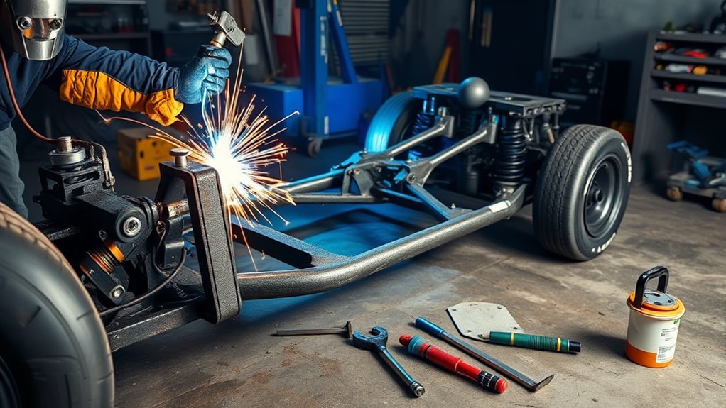
Welding coilover mounts is structural suspension work, not a basic bracket repair. The mounts must carry vehicle weight and repeated impact loads while keeping the coilover aligned through full compression and droop. Use the suspension manufacturer’s dimensions and hardware, and have a qualified chassis fabricator design, weld, or inspect the installation before the vehicle is driven.
Quick Answer
To weld coilover mounts safely, set the vehicle at its loaded ride height, calculate compression and rebound reserve, clamp and tack compatible brackets, then cycle the suspension with the spring removed. Reinforce the load path, finish-weld with controlled heat, verify alignment, inspect the welds, and recheck everything after a low-speed shakedown.
Warning: Coilover mounts are safety-critical chassis parts. Do not weld near fuel vapors, a fuel tank, fuel or brake lines, undercoating, upholstery, wiring, batteries, or enclosed cavities until the hazards have been removed or made safe under a proper hot-work procedure. Keep suitable extinguishing equipment ready, inspect both sides of every panel, and maintain a fire watch for at least 30 minutes after welding when combustible materials or hidden spaces are exposed.
Key Takeaways
- Use mounts, spacers, bolts, and reinforcement that match the coilover and the chassis material.
- Set the vehicle at its intended loaded ride height and measure both sides from fixed chassis points.
- Confirm shock travel with measurements, then cycle the suspension with the springs removed before final welding.
- Do not use a universal shock-angle limit. Follow the suspension design and account for motion ratio, spring rate, damping, and side loading.
- Tack first, remeasure, reinforce the full load path, control welding heat, and inspect the finished assembly before road use.
At a Glance
| Time Required | Several hours to multiple days, depending on mockup, fabrication, welding access, cooling, alignment checks, coating, and reassembly |
| Difficulty | Advanced fabrication; structural automotive welding and suspension-layout experience required |
| Tools Needed | Suitable MIG or TIG equipment, grinder, wire brush, non-chlorinated cleaner, jack stands or chassis stands, level, plumb bob, tape measure, angle finder, clamps, marker, PPE, and fire extinguisher |
| Cost | Varies widely with the mount kit, crossmember or tubing, hardware, coatings, alignment work, and professional fabrication or inspection |
Before You Weld: Confirm the Conversion Plan
Start with the coilover or suspension-kit instructions, not a generic bracket position. Confirm that the kit is intended to carry the vehicle’s sprung weight at the proposed mounting points. A factory shock mount designed only for damper loads may not be strong enough for a coilover that also carries the spring load.
Identify the material and thickness of every part you plan to weld. Do not assume an unknown bracket, axle center section, frame section, or suspension component is mild steel. Cast iron, cast steel, aluminum, high-strength steel, plated parts, and heat-treated components may need a different design, filler metal, preheat, post-weld treatment, or no welding at all. When the material or load path is uncertain, stop and have the design reviewed.
Check local inspection, registration, insurance, and motorsport rules before modifying a road vehicle. Requirements vary, and a sound weld does not automatically make an unapproved suspension layout road-legal.
Choose Coilover Mounts and Verify the Plan
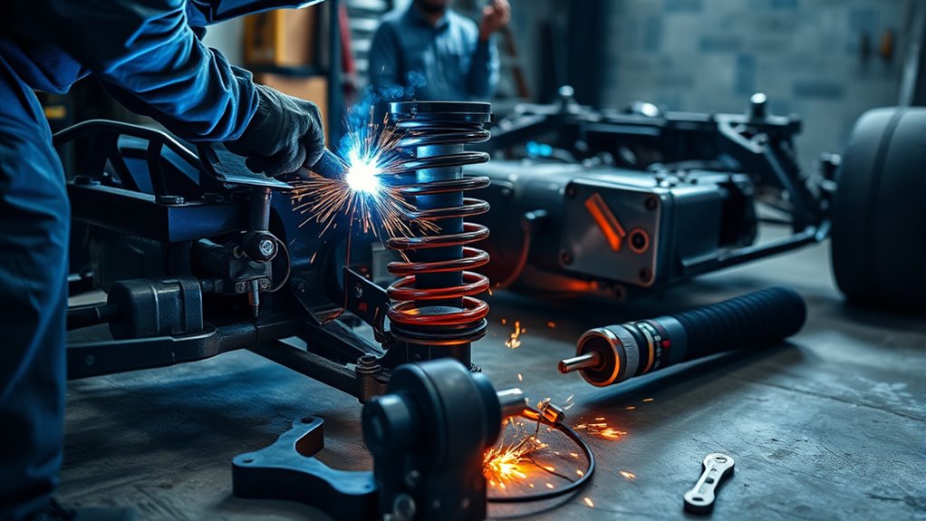
Choose coilover mounts that match the vehicle, coilover eyelet width, bolt diameter, bushing or spherical-bearing style, and suspension layout. The brackets must sit square to the shock ends without twisting the body or pinching the bearing. Use the correct misalignment spacers, sleeves, tabs, and manufacturer-specified hardware. Do not enlarge holes at random or use stacks of washers to make a narrow shock fit a wide bracket.
For most mild-steel chassis and frame-rail work, use weldable steel brackets and steel reinforcement tubing specified for the kit. Aluminum mounts are suitable only when they are part of an engineered system designed for that material and attachment method. Material compatibility matters because the bracket, weld, fastener, crossmember, and surrounding chassis must act as one load path.
Where the suspension design allows it, support the coilover eye in double shear, with a bracket tab on both sides of the bearing. A single-shear mount places more bending load on the bolt and bracket, so it should be used only when the engineered kit specifically calls for it.
Products Worth Considering
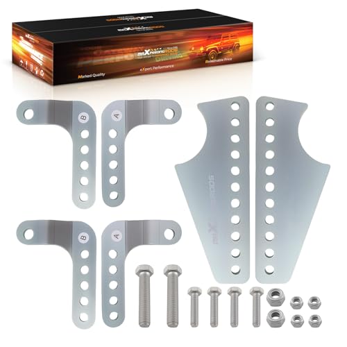
[Fitment] Universal weld-on shock mount brackets, for 3” diameter axle tubes, for most Coilover shocks

Coil-over shock mounting bracket is a wide flat mount model and is a weld-on style
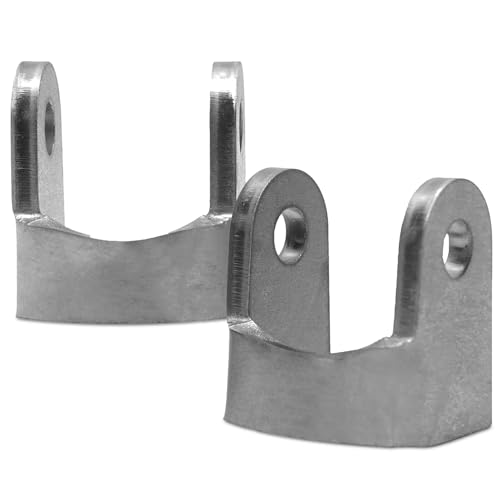
HEAVY-DUTY STEEL CONSTRUCTION: Manufactured from 1/4 inch raw steel, this flat shock mount bracket is designed for durability and consistent performance. Ideal for weld-on suspension setups, it provides a solid mounting solution for shock absorbers and coilovers in off-road, racing, and custom vehicle builds.
Record Coilover Dimensions and Travel
Before cutting or welding, record the coilover’s compressed length, extended length, total stroke, eyelet width, bolt size, spring outside diameter, bump-stop arrangement, and manufacturer’s recommended ride-height length. Measure eyelet-to-eyelet shocks from the center of one mounting hole to the center of the other.
Use these simple checks during mockup:
- Compression reserve = installed shock length at ride height minus compressed length.
- Rebound reserve = extended length minus installed shock length at ride height.
- Usable stroke must remain within the manufacturer’s limits after accounting for the bump stop, droop limiter, motion ratio, and suspension arc.
QA1’s custom coilover measuring guide recommends setting the vehicle at its intended stance, measuring between the planned mounting points, and checking that the suspension still has adequate compression and extension travel. Do not copy a travel split from another vehicle; street, drag, off-road, and road-course applications can need different compression and rebound reserves.
Set Coilover Angle From the Suspension Geometry
Keep the coilover aligned as closely as practical with the suspension’s intended motion, but do not use a universal angle limit. Measure the angle from true vertical and compare it with the kit or shock manufacturer’s instructions. Leaning a coilover changes its motion ratio and reduces the spring and damper effect at the wheel, which can require different spring rate and valving.
The upper and lower bearings must articulate freely through the complete suspension arc. If the body, shaft, spring, reservoir hose, or adjuster is forced sideways at any point, change the pickup point or bracket orientation before welding.
Note: QA1 explains that coilover angle changes the effective spring and damping behavior. Treat angle as a suspension-design input, not a cosmetic choice or a fixed “under 30 degrees” rule.
Prepare the Frame Rails and Rear Axle Housing
Support the vehicle on rated stands placed under structurally sound points, with the chassis stable and level. Remove the coil springs and any shock, bushing, hose, fuel component, wiring, trim, or heat-sensitive part that could be damaged. Follow the vehicle service information for battery disconnection and protection of electronic modules before welding.
Products Worth Considering

Well-woven Fiberglass Blanket: Constructed from 24.7 oz/yd² fiberglass material, this welding blanket serve as an excellent shield against heat and fire. Tight stitching and exquisite weaving. Our heat resistant mat shield is a nice addition to welding equipment. Standard size : 4x6 ft (122x183cm), thickness: 0.31” (8mm)

Extreme Heat Resistance (3000°F+) – Carbon Fiber Welding Blanket Made of high-density carbon felt welding blanket, our fireproof welding blanket certified to ASTM D6413 and UL94-V0, withstands extreme temperatures over 3000°F — Outperforms standard fiberglass welding blankets (1000°F limit)Much more effective at stopping spatter than fiberglass offerings, and doesn't shed glass fibers!

【Fiberglass Welding Blanket】 : Made of 24.7 oz/yd² fiberglass fabric, the welding blanket provides excellent thermal protection and withstands up to 1,022℉ (550℃) working temperatures. Effectively protecting welders and property from heat, embers, sparks and spatter. NOTE: There are fiberglass on the surface of the welding blanket, please wear gloves when you check it.
Control Fire, Fumes, and Hidden Combustibles
Follow the hot-work controls in OSHA 29 CFR 1910.252. Move combustible material away from the work area where practical, shield anything that cannot be moved, keep suitable extinguishing equipment ready, and inspect openings or the opposite side of panels where sparks and conducted heat can reach hidden material.
OSHA calls for a fire watch when significant combustibles are within 35 feet, when sparks can reach easily ignited material, or when openings expose hidden combustibles. When those conditions apply, keep the fire watch in place for at least 30 minutes after welding.
Remove paint, seam sealer, rubberized undercoating, oil, zinc coating, and unknown plating from the weld zone using a safe method. Provide effective ventilation for welding fumes. Never use chlorinated brake cleaner or allow chlorinated-solvent vapors near an arc; use a manufacturer-approved non-chlorinated cleaner, let the metal dry fully, and keep the cleaner container away from the hot-work area.
Do not weld in an explosive atmosphere or on an uncleaned cavity, tank, or part that may contain flammable vapor. Hollow spaces that will be heated must be safely vented or handled by a qualified professional under an approved procedure.
Clean and Inspect the Frame Rails
Clean the frame rails, crossmember area, and axle housing to bright metal. The weld zone must be free of rust scale, paint, sealer, grease, moisture, and plating. Place the welding work lead on clean metal close to the joint when practical, following the welder and vehicle manufacturer’s instructions.
| Step | Action |
|---|---|
| 1 | Remove paint, rust, undercoating, seam sealer, plating, and scale from the complete weld zone. |
| 2 | Clean with an approved non-chlorinated product and let every surface dry fully. |
| 3 | Inspect for cracks, deep pitting, thin metal, prior collision damage, or questionable repairs. |
| 4 | Mark the mount locations, remove burrs, and clean the contact areas again. |
| 5 | Remove or shield lines, wiring, upholstery, coatings, and combustible material on both sides of the work. |
Repair or replace weak metal before adding a coilover load. A thick bracket does not make a rusted, thin, or cracked frame section safe.
Check Chassis and Rear Axle Alignment
Level the chassis front to back and side to side, then measure from fixed chassis points to the axle housing on both sides. Check axle centering, wheelbase, pinion angle, frame-rail width, tire position, and the centerline of the planned crossmember. Hold the axle at the intended ride height and orientation before marking brackets.
Confirm that the rear axle housing is weldable in the proposed area. Do not weld directly to a cast center section or unknown housing material without an approved procedure. Welding heat can distort axle tubes and crossmembers, so plan a balanced tack and weld sequence and verify alignment again after cooling. A housing that contains finished gears, bearings, seals, or lubricant may need to be stripped, jigged, and welded by an axle specialist.
Set Ride Height and Mark the Mount Points
Set the vehicle at its intended loaded ride height. If the build is incomplete, simulate the expected engine, fuel, battery, interior, cargo, and driver weight as accurately as practical. Mark all measurements from fixed chassis references rather than the floor alone, because tire pressure and floor irregularities can mislead you.
Set Ride Height Under Load
Measure the chassis at several points and make sure it is level before you locate the mounts. Record the target chassis height and the coilover’s installed eye-to-eye length. QA1’s shock ride-height guidance explains that shock ride height is the distance between the shock mounting points at the vehicle’s assembled stance, not simply the ground clearance.
Compare the installed length with the compressed and extended lengths. The shock must have enough usable movement for the intended application without reaching an internal stop. The bump stop should control maximum compression before the shock bottoms internally, and a limit strap or the suspension geometry should control droop when the manufacturer does not allow the shock to act as the extension stop.
Mark Shock Centers and Mount Width
Use a plumb bob, level, straightedge, tape measure, and angle finder to transfer each shock centerline to the frame and axle brackets. Measure both sides from the same fixed references and record the distances before tacking.
Mock up the actual bearings, bushings, sleeves, and misalignment spacers. The bracket width should support the eye without crushing the bearing or leaving a gap that must be pulled closed with the bolt. The upper and lower bolts should remain parallel unless the manufacturer specifies another arrangement.
Verify Mount Alignment and Clearance
Install the coilover body without the spring and move the suspension through full bump, ride height, and full droop. Check that the bearings rotate freely and that the shaft is not side-loaded. Use the real spring or a tube cut to the spring’s outside diameter during the clearance check so the final assembly does not contact the tire, frame, body, exhaust, brake hose, sway bar, panhard bar, or other suspension links.
Pro Tip: Write the ride-height length, compressed-length reserve, rebound reserve, shock angle, bracket width, and left-to-right reference measurements on tape beside the work area. Recheck that list after every tack.
Tack Weld the Coilover Mounts
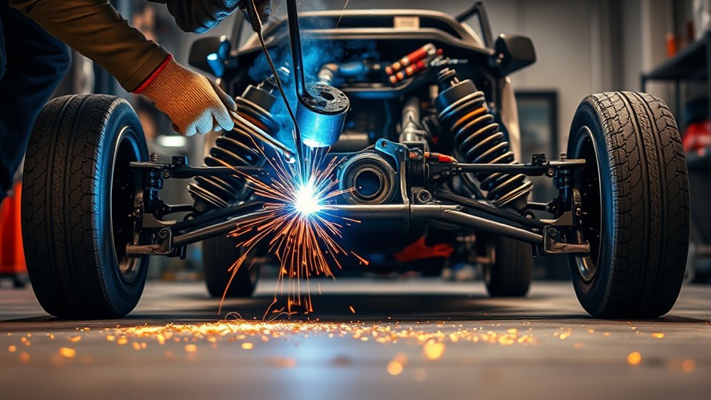
Clamp the coilover mounts so they cannot move, then place short tack welds on opposing sides of each bracket. Alternate the tack locations instead of heating one edge continuously. The tacks must be strong enough for mockup but small enough to remove cleanly if a measurement changes.
After each set of tacks, check the bracket against the centerline, ride-height, angle, and width measurements. Reinstall the springless coilover and cycle the suspension again. If a mount moved, cut the tack, restore the clean fit, and correct the position before adding more weld.
Use welding equipment with enough output and duty cycle for the joint thickness and position. The person welding should be trained and qualified for the process and material. OSHA 29 CFR 1910.254 requires arc-welding operators to be properly instructed and qualified to use the equipment safely.
Cycle the Coilover Through Full Travel
Do not judge the layout only at ride height. Move the suspension slowly through the full usable stroke with the spring removed. Check the shock body, shaft, bump stop, bearing spacers, adjuster, reservoir hose, brake hose, tire, wheel, exhaust, frame, crossmember, and suspension links at several points in the arc.
At full compression, confirm that the designed bump stop engages before the shock bottoms and before the spring reaches coil bind. At full droop, confirm that the spring remains correctly seated if the design requires it, the brake hose and wiring retain slack, and the shock is not used as a hard travel stop unless the manufacturer explicitly permits it.
Turn or articulate any component that changes clearance during use. On a front suspension, check lock-to-lock steering at bump and droop. On a live rear axle, check both sides together and one side at a time to simulate body roll and axle articulation.
A coilover mount that clears at static ride height can still bind, bottom out, damage a brake hose, or contact a tire when the suspension rolls or reaches full travel.
Reinforce the Frame and Crossmember
Reinforce the frame and crossmember with steel tubing, plate, gussets, or kit-supplied structures that carry the load into sound chassis metal. The load path should not end at a small tab welded to thin, unsupported sheet metal. Tie upper mounts into a rigid crossmember or reinforced tower, and spread the load over enough sound material to avoid local tearing or fatigue.
On a unibody vehicle, the mount may need reinforcement that connects several structural layers, a cage, subframe connectors, or a manufacturer-designed conversion structure. Do not guess at the reinforcement for a unibody, back-halved, caged, off-road, or competition vehicle.
Set the crossmember at ride height, tack it first, and verify that it remains level and square. Check exhaust, driveshaft, floor, seat, fuel tank, and service access before final welding.
The bracket, weld, crossmember, frame reinforcement, bolt, and coilover bearing must work as one continuous load path.
Weld the Final Passes and Control Heat
Remove the coilover, spring, rubber or polyurethane bushings, wiring, hoses, fuel-system parts, and other heat-sensitive components before final welding. Clean the joint again and confirm the bracket fit-up, root opening, weld access, and material specification.
Use the correct welding process, filler metal, shielding gas, polarity, and settings for the verified base metals and thicknesses. Practice on matching scrap and cut or bend a test coupon when practical. A bead that looks smooth does not prove adequate fusion or penetration.
Finish-weld in a planned sequence, using short sections and alternating sides or brackets to limit distortion. Let the assembly cool naturally between sections. Do not quench a structural weld with water. When welding to an axle tube or long crossmember, monitor alignment as the work progresses and recheck it after the part reaches ambient temperature.
Do not grind a structural weld flat for appearance. Remove only defects that will be repaired, sharp spatter, or material that interferes with assembly or inspection. If a weld shows cracking, undercut, lack of fusion, porosity, or burn-through, remove the defect using an approved repair method and reweld it rather than covering it with another pass.
Test Clearance and Inspect the Welds
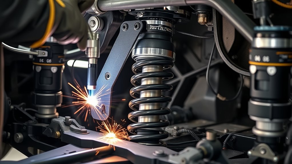
After the welds cool, measure the mounting points again and cycle the suspension through compression, rebound, body roll, and steering movement where applicable. Recheck the installed shock length at ride height, compression reserve at full bump, rebound reserve at full droop, and spring clearance through the complete arc.
Inspect each weld with bright light and clean access. Look for visible cracks, undercut, missed edges, porosity, overlap, incomplete tie-in, burn-through, arc strikes, and distortion. Visual inspection cannot confirm everything inside a structural weld. If the material, joint, penetration, or load path is uncertain, have a qualified inspector or chassis fabricator examine it before assembly.
| Check | Pass Standard |
|---|---|
| Full compression | The designed bump stop engages before internal shock bottoming, spring coil bind, or component contact. |
| Full droop | The shock, spring, brake hose, wiring, and suspension links are not overextended or unseated. |
| Alignment | Both sides match the recorded ride-height, angle, centerline, and bracket-width measurements. |
| Weld face | The weld is continuous where specified, tied into both parts, and free of visible cracks, severe undercut, overlap, or porosity. |
| Clearance | No tire, spring, shock, exhaust, brake-line, frame, body, or linkage contact occurs through the full motion. |
| Fasteners and bearings | Correct bolts, spacers, washers, locking hardware, and free bearing articulation are present. |
Correct any interference, questionable weld, or shifted dimension before the vehicle is driven. Keep a written record of ride height, shock length, shock angle, mount spacing, fastener specifications, and the changes made during fabrication.
Protect the Finished Work and Road-Test Carefully
After final inspection, clean the bare steel and apply a compatible primer, paint, cavity coating, or other corrosion protection. Do not coat the weld until the inspection is complete. Restore any seam sealer, heat shield, line clip, or underbody protection without covering a problem or trapping moisture.
Install the coilovers with the specified bolts, spacers, washers, and locking hardware. Torque every fastener to the coilover, suspension-kit, or chassis manufacturer’s specification. If no reliable torque value exists for a safety-critical fastener, do not guess; obtain the specification from the component maker or a qualified engineer.
Lower the vehicle carefully, settle the suspension, and measure ride height again. Check alignment before normal driving. Start with a low-speed shakedown in a controlled area, listen and feel for contact or movement, then inspect every mount, weld, bolt, hose, and clearance point again. Recheck fastener torque at the interval specified by the component manufacturer.
Common Coilover-Mount Welding Mistakes
- Locating the mounts before the vehicle is at its intended loaded ride height.
- Using a universal shock angle instead of checking motion ratio, spring rate, damping, and bearing articulation.
- Final-welding before cycling the springless suspension through bump, droop, roll, and steering movement.
- Attaching a coilover bracket to thin sheet metal or an original shock mount that was not designed to carry spring load.
- Using the shock as the compression or droop stop without manufacturer approval.
- Pulling a bracket closed with the mounting bolt instead of using the correct spacers and bracket width.
- Welding over paint, undercoating, plating, rust, grease, or cleaner residue.
- Concentrating heat on one side and failing to recheck axle-housing or crossmember alignment.
- Grinding away a sound structural weld to make it look flat.
- Assuming a good-looking bead proves penetration, material compatibility, or a safe load path.
Frequently Asked Questions
Can you weld suspension mounts?
Yes, suspension mounts can be welded when the design, base material, joint, welding procedure, reinforcement, and load path are correct. Because the mounts are structural, a qualified automotive or motorsport fabricator should perform or inspect the work before the vehicle is driven.
What kind of welder do I need for steel coilover mounts?
A properly configured MIG or TIG welder may be suitable for verified weldable steel, but the machine must have enough output and duty cycle for the joint thickness and position. Process choice alone does not make the weld safe; material identification, filler selection, fit-up, penetration, and operator skill also matter.
Should coilover mounts be double shear?
Double-shear mounting is generally preferred when the suspension design and available space allow it because the shock eye is supported on both sides. Use the bracket arrangement supplied or approved by the suspension manufacturer rather than converting a designed single-shear or double-shear mount without engineering review.
Can you weld coilover mounts to a unibody car?
Only with a properly designed reinforcement structure. Thin unibody sheet metal usually cannot accept a concentrated coilover load through a small tab. The mount may need to tie into multiple structural layers, a reinforced tower, subframe connectors, or a roll structure designed by an experienced chassis fabricator.
Can you weld coil springs?
No. Welding heat can change the properties of spring steel and create a dangerous failure point. Use the correct spring, spacer, seat, mount, or manufacturer-approved adapter instead.
Can a shock absorber or coilover body be welded?
Do not weld a complete shock absorber or coilover body. Heat can damage seals, oil, gas pressure, internal valving, bearings, and plating. Remove the coilover and weld only the approved external chassis or axle brackets.
How much coilover angle is too much?
There is no single safe angle for every suspension. Measure the angle from vertical and follow the coilover or suspension manufacturer’s limits. Greater angle changes motion ratio and reduces effective spring and damping force at the wheel, so spring rate, valving, travel, and side loading must be checked together.
Should I paint the coilover mount welds?
Yes, after the welds have cooled and passed inspection. Clean the area and apply a compatible primer, paint, or corrosion coating. Leave the welds visible until inspection is finished, then protect the bare steel and restore any necessary seam sealer or cavity protection.
Does the vehicle need an alignment after coilover-mount fabrication?
Yes. Changing ride height or suspension pickup points can alter alignment, axle position, pinion angle, and corner weights. Measure the chassis after welding, align the vehicle before normal driving, and recheck the mounts and fasteners after the initial shakedown.
Conclusion
Safe coilover mount fabrication depends on more than making a strong-looking weld. Confirm the materials and load path, set the vehicle at its intended loaded ride height, measure shock travel, tack the brackets, and cycle the springless suspension through its complete motion. Reinforce the chassis, control heat, verify alignment after cooling, and have questionable structural welds inspected before final assembly. After the first controlled shakedown, recheck ride height, clearance, alignment, weld condition, and every fastener.
Sources
- OSHA 29 CFR 1910.252, Welding, Cutting, and Brazing: General Requirements — fire prevention, 35-foot combustible controls, fire-watch duration, ventilation, coatings, confined spaces, and cleaning-solvent precautions.
- OSHA 29 CFR 1910.254, Arc Welding and Cutting — arc-welding equipment and operator instruction requirements.
- QA1: How to Measure for Custom Coil-Overs — ride-height measurement, shock travel, mount-load capacity, and springless mockup guidance.
- QA1: What Is Shock Ride Height and How Do You Measure It? — installed shock length, compression and rebound reserve, and loaded ride-height setup.
- QA1: Does the Angle of My Coilover Shocks Matter? — how coilover angle changes motion ratio, effective spring rate, and damping behavior.
- Miller: The Fundamentals of Welding — joint cleaning, process selection, and basic welding-equipment considerations.