
Welding a vehicle frame rail is a structural collision repair, not a general fabrication job. Before you cut, grind, straighten, or weld anything, identify the exact rail, material, damage limits, and repair procedure for the vehicle’s year, make, model, and body style. If the manufacturer does not authorize the repair, replace the specified component or send the vehicle to a qualified structural repair facility.
Quick Answer
You should weld a frame rail only when the current vehicle-specific repair procedure permits it. Measure and secure the structure, identify the material, electrically isolate the vehicle, remove coatings and fire hazards, use the specified joint and attachment method, test the welder on matching material, then inspect, measure, scan, align, and protect the completed repair.
Key Takeaways
- The vehicle maker’s current repair procedure controls whether a rail may be repaired, sectioned, or welded.
- Material thickness alone does not determine the welding process, wire, joint, reinforcement, or weld location.
- Documented three-dimensional measurements are needed before, during, and after structural work.
- Follow the OEM procedure for 12-volt isolation, SRS precautions, and hybrid or electric vehicle high-voltage disablement.
- Complete weld testing, corrosion protection, diagnostic scans, alignment, and required calibrations before returning the vehicle to service.
At a Glance
| Time Required | Varies by damage, measuring, disassembly, replacement procedure, curing time, inspections, scans, alignment, and calibration. This is rarely a quick repair. |
| Difficulty | Expert structural collision repair. It requires training in vehicle construction, measuring, welding, electrical safety, and quality control. |
| Tools Needed | Current OEM repair information, approved frame bench or rack, three-dimensional measuring equipment, specified welder and wire, clamps or fixtures, test coupons, fume extraction, PPE, fire protection, scan tool, and alignment equipment. |
| Cost | Damage-dependent. OEM information subscriptions, approved equipment, structural measuring, replacement parts, scans, alignment, and calibrations make this a professional-shop repair. |
What’s in This Article
- Before You Weld Frame Rails
- Why Frame Rail Integrity Matters
- Determine Whether the Frame Rail Can Be Welded
- Prepare and Measure the Vehicle
- Choose the Approved Attachment Method
- Follow the Specified Welding Procedure
- Inspect and Verify the Repair
- Restore Corrosion Protection
- Common Mistakes to Avoid
- Frequently Asked Questions
- Conclusion
- Sources
Before You Weld Frame Rails
First, confirm what the word frame rail means on the vehicle in front of you. A pickup or body-on-frame SUV may have a separate ladder-type frame. A unibody vehicle uses welded structural rails, side members, reinforcements, floors, pillars, and crossmembers as one load-carrying structure. The repair rules for these designs are not interchangeable.
Obtain the current body repair or collision repair procedure by vehicle identification number when possible. Do not rely on a saved procedure from another model year, a general welding chart, or a repair that looks similar. Construction materials, internal reinforcements, attachment methods, and approved sectioning locations can change within the same model line.
Warning: Do not weld a vehicle frame rail when you cannot confirm the material, repair limits, sectioning location, attachment method, joint design, electrical-isolation procedure, and final inspection requirements.
Do Not Start the Repair When
- The rail has severe rust-through or widespread internal corrosion.
- The damage extends beyond an approved sectioning or partial-replacement location.
- The rail contains a kink, tear, crush, buckle, or heat damage that the manufacturer classifies as non-repairable.
- The part is made from an unknown material or steel strength.
- The repair would cross a reinforcement, crush initiator, suspension mounting point, steering mounting point, powertrain mount, seat-belt anchorage, or other restricted area.
- The required replacement part, fixtures, welder, wire, training, or measuring equipment is unavailable.
- The vehicle cannot be safely de-energized.
- Local inspection, insurance, salvage, or roadworthiness rules prohibit the proposed repair.
Tools, Information, and Safety Equipment
- Current vehicle-specific body repair procedure and dimensions
- Approved frame bench, rack, anchoring system, or dedicated fixtures
- Three-dimensional measuring system or the exact measuring method required by the manufacturer
- Specified welding, brazing, riveting, bonding, or fastening equipment
- Approved wire, electrodes, adhesives, rivets, primers, sealers, and corrosion-protection products
- Matching material for welder setup and destructive test coupons
- Welding helmet, safety glasses, gloves, jacket, hearing protection, and suitable footwear
- Local exhaust ventilation and respiratory protection selected for the coating and welding hazards
- Fire-resistant blankets, shields, extinguisher, and a fire watch when required
- Scan tool, battery-support equipment, wheel-alignment equipment, and any required ADAS calibration targets
Review basic arc welding protective clothing before working around sparks, ultraviolet radiation, hot metal, and grinding debris.
Why Frame Rail Integrity Matters
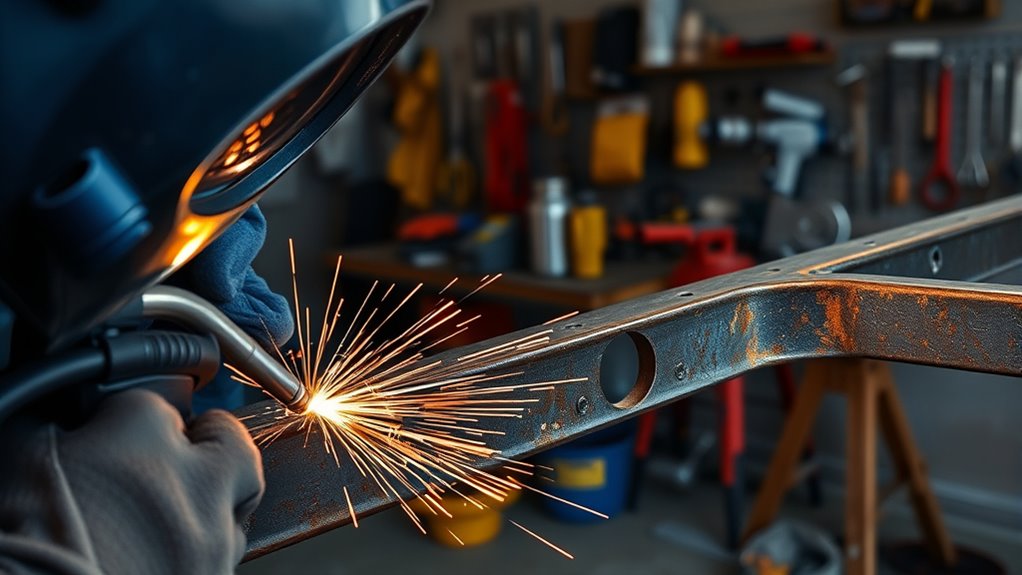
Frame rails help manage suspension, steering, powertrain, towing, payload, and collision loads. Their shape, material, thickness, reinforcements, holes, joints, and crush zones are part of the vehicle’s engineered load path.
A repair can look straight while the structure remains high, low, twisted, diamond-shaped, or shifted sideways. That hidden movement can affect panel fit, suspension geometry, wheel alignment, steering behavior, sensor aiming, occupant protection, and future collision performance.
A smooth-looking bead does not prove that a frame rail has been restored to its original dimensions, material properties, attachment strength, or crash-management function.
Look for rust perforation, cracks, torn spot welds, buckling, kinks, stretched holes, damaged crossmembers, displaced suspension mounts, cracked coatings, and signs of an older repair. Continue the inspection beyond the visible damage because collision force can travel into another rail, floor, pillar, rocker, crossmember, or mounting point.
Determine Whether the Frame Rail Can Be Welded
Do not choose a welding process until you know that the rail is repairable. The current OEM procedure must answer four questions:
- May the damaged part be straightened, repaired, sectioned, partially replaced, or only replaced at factory seams?
- Where may the cut and joint be placed?
- Which attachment methods are approved?
- Which materials, tools, settings, wire, joint design, and quality tests are required?
Rules can differ sharply between manufacturers. Some makers publish limited rail sectioning locations. Others prohibit sectioning on particular full-frame vehicles or structural components. Honda and Acura also limit approved steel welding methods according to tensile strength and the model-specific procedure. Review the Honda and Acura welding and sectioning guidelines for an example of how detailed these restrictions can be.
Identify the Material Before Applying Heat
A modern rail may contain more than one steel strength, a tailored blank, a reinforcement, an aluminum extrusion, a casting, or a mixed-material joint. A magnetic test or thickness measurement alone does not identify the grade or tell you whether welding is permitted.
Uncontrolled heat can change the properties of high-strength and ultra-high-strength steel. Aluminum parts may also have strict repair, heat, contamination, tooling, and inspection limits. Use the material map and repairability guidance in the body repair manual.
Note: Replacement at factory seams is not automatically the same as sectioning. Sectioning creates a new joint in a location selected or approved by the manufacturer.
Prepare and Measure the Vehicle
1. Document the Damage
Photograph the vehicle, damaged areas, corrosion, previous repairs, panel gaps, suspension positions, warning lights, and any disconnected parts. Record pre-repair diagnostic trouble codes and complete any OEM-required pre-repair scan.
2. Measure Before Cutting
Mount and anchor the vehicle as required. Obtain vehicle-specific datum dimensions and measure the structure in length, width, and height. Check nearby suspension, crossmember, body, and mounting points. Record the results so you can compare them during and after the repair.
A straightedge, tape measure, tram gauge, or visual check may help with preliminary inspection, but it does not replace a required three-dimensional measuring system or dedicated fixture.
3. Restore Alignment Before Final Fit-Up
Correct permitted structural movement with the specified rack, bench, anchoring method, pulling direction, and fixtures. Some manufacturers prohibit particular pulling or heating operations. Do not use heat to straighten a rail unless the current procedure expressly permits it.
Measure throughout the operation rather than waiting until the end. Test-fit adjoining panels, crossmembers, suspension parts, and replacement sections before final welding.
4. Electrically Isolate the Vehicle
Follow the OEM sequence for the 12-volt battery, supplemental restraint system, capacitors, memory functions, and sensitive electronic modules. Do not assume that removing one battery cable completes the procedure.
Hybrid and electric vehicles require model-specific high-voltage disablement, personal protective equipment, verification that voltage is absent, and any specified waiting period. Only trained personnel should perform those steps. Tesla, for example, instructs repairers to complete its vehicle electrical-isolation procedure before welding.
Warning: Never cut, drill, clamp, pull, or weld near an energized high-voltage battery, cable, busbar, pyrotechnic device, airbag component, fuel line, fuel tank, brake line, refrigerant line, or pressurized system.
5. Inspect Both Sides of the Work Area
Remove or protect wiring, control modules, hoses, brake lines, fuel-system parts, carpet, trim, foam, insulation, sound deadener, seam sealer, undercoating, cavity wax, and other combustible materials. Heat can travel through a rail and ignite material on the opposite side or inside a closed section.
Keep a suitable extinguisher within reach. Use fire-resistant blankets and shields without trapping heat against sensitive parts. Assign a fire watch when the hot-work assessment or local rules require one, and inspect the area again after welding has stopped.
6. Clean Only the Required Area
Remove rust, oil, dirt, paint, sealer, undercoating, and damaged coating far enough to complete the specified joint and inspect the surrounding metal. Do not thin the rail while grinding.
For general cleaning principles, review these clean base metal tips. However, the vehicle procedure and coating-product instructions control the abrasive, cleaning method, and amount of coating removal.
Coated steel can release hazardous fumes. Use source extraction and the respiratory protection required by the hazard assessment. General guidance on removing zinc-containing coatings does not replace the vehicle-specific preparation instructions.
7. Prepare the Joint and Replacement Part
Reproduce the specified cut line, overlap, open-butt joint, backing plate, sleeve, flange, plug-weld hole, adhesive area, or factory-seam arrangement. Do not create your own fish plate, gusset, sleeve, bevel, scarf, lap joint, or reinforcement.
Remove only the coatings required for the approved attachment method. Protect surfaces that will become inaccessible after installation with the exact primer or corrosion product required by the procedure.
Choose the Approved Attachment Method
The word MIG is often used loosely in automotive repair. The procedure may instead call for gas metal arc welding, commonly written as GMAW or MAG, squeeze-type resistance spot welding, MIG brazing, structural adhesive, rivets, bolts, flow-form rivets, self-piercing rivets, or a combination of methods.
| Attachment Method | Use It Only When |
| Squeeze-type resistance spot welding | The procedure specifies spot welds and the machine can produce the required current, force, access, and test results. |
| GMAW or MAG plug welding | The plug-weld location, hole size, weld count, spacing, wire, gas, and preparation are specified. |
| GMAW or MAG butt welding | The sectioning procedure permits a butt joint at the named location and defines the gap, backing, sequence, and finishing limits. |
| MIG brazing | The procedure calls for brazing wire and the technician has the specified equipment and training. |
| Adhesives and mechanical fasteners | The product, surface preparation, bead pattern, fastener type, installation tool, cure conditions, and combination with welds are specified. |
| Stick welding or SMAW | The vehicle or frame maker expressly approves it for that component and provides a qualified procedure. Do not assume it is acceptable for a modern vehicle structure. |
Products Worth Considering

Heavy-Duty HSS Spot Weld Cutter : Made from premium High-Speed Steel (HSS) with cutting edge hardness up to 63–66 HRC, this spot weld cutter delivers exceptional durability, sharpness, and strong penetration power for fast and efficient metal cutting

Durable HSS Construction: Our spot weld cutter set is made of HSS for better durability and wear resistance. The double-sided blades ensure long-term use and consistent performance, making it the ideal tool of choice for metal cutting

Separates Spot Welded Panels.
Choose the Correct Wire and Consumables
Match the wire to the repair procedure, base material, welder, transfer mode, shielding gas, and required strength. Standard ER70S-6 wire is not automatically suitable for every high-strength steel joint.
E7018 is a covered electrode for shielded metal arc welding, not MIG wire. A general stick welder settings chart may help with ordinary SMAW practice, but it does not authorize stick welding on a vehicle frame rail.
Use Process-Specific Primer Instructions
Do not apply weld-through primer to every hidden flange. Honda’s current general guidance, for example, calls for zinc-rich weld-through primer on specified resistance spot-welded mating surfaces but says not to use it for MAG plug welds, MAG butt welds, or MIG brazing. Follow the vehicle maker’s procedure and the approved product instructions.
Set Up the Welder on Matching Material
Use matching material, thickness, coating condition, layers, wire, gas, joint geometry, and welding position. Set the machine according to the OEM procedure, approved equipment instructions, and test results. A chart on the welder is a starting reference, not proof that the structural joint is acceptable.
Pro Tip: Complete the required test welds before touching the vehicle. Peel, twist, bend, chisel, or cut the coupons as specified so you can inspect nugget size, penetration, fusion, porosity, and failure location.
Follow the Specified Welding Procedure
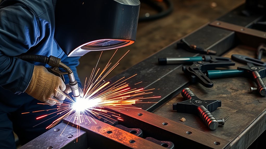
Complete every step in the published order. The procedure may control the rail position, support points, weld sequence, joint gap, plug-weld diameter, weld count, spacing, access holes, adhesive placement, cooling time, and grinding limits.
Products Worth Considering

Value Pack: The package includes 24 packs of butt welding clamps, enough quantity to meet your daily needs and replacements. Each butt welding clamps is individually wrapped in a small bag, convenient to carry and use.

16-Pack Welding Clamps Set: Includes 16 butt welding clamps designed for precise edge-to-edge welding, ideal for body repair, floor patching, door skins, and sheet metal alignment.

PACKAGE INCLUDES - You will receive 24 pack silver butt welding clamps, each measuring 2.3 × 1 inch, lightweight and compact, a necessary tool for sheet metal, body repair and other industries.
Maintain Fit-Up and Dimensions
Clamp or fixture the replacement section so it cannot move. Confirm measurements before tacking, after tacking, during welding, and after the joint cools. Recheck adjoining parts and panel fit without forcing them into place.
Control the Heat-Affected Zone
Use the specified voltage, wire feed, current, pulse program, gas flow, torch angle, stickout, travel speed, and weld sequence. Do not replace the published sequence with a generic “short welds in different places” method unless the procedure allows it.
Avoid unnecessary starts, stops, overwelding, excessive buildup, undercut, incomplete fusion, burn-through, porosity, and grinding. Do not heat-shrink, flame-straighten, or quench the rail unless the manufacturer expressly permits the operation.
Do Not Add Unapproved Reinforcement
A large fish plate, sleeve, or gusset may make one area stiffer while moving stress to the edge of the reinforcement. It can also interfere with the intended crush path. Install reinforcement only when the repair procedure gives its material, shape, thickness, length, location, orientation, attachment method, and corrosion treatment.
Protect the Vehicle During Welding
- Position the work return clamp as instructed and close enough to the weld to limit current paths through bearings, modules, or wiring.
- Keep welding cables away from high-voltage parts, fuel components, pyrotechnic devices, and sensitive harnesses.
- Watch the rear side and inside of the rail for heat, smoke, molten metal, or ignition.
- Maintain fume extraction without pulling away the shielding gas.
- Stop immediately if the part moves, a crack grows, contamination appears, the weld test changes, or an electrical or fire hazard develops.
Inspect and Verify the Repair
Inspect the joint before grinding, coating, sealing, or installing trim. Compare it directly with the repair procedure and the accepted test coupon.
Check the Weld or Attachment
- Correct joint location, shape, overlap, gap, backing, sleeve, or flange
- Correct weld type, number, diameter, length, spacing, and sequence
- Complete fusion without cracks, pinholes, porosity, undercut, burn-through, cold lap, or excessive buildup
- Correct rivets, fasteners, adhesive coverage, squeeze-out, cure conditions, and combinations of attachment methods
- No excessive grinding or thinning of the rail or adjoining panel
- No damaged wiring, hoses, lines, modules, glass, trim, coatings, or nearby components
Use only the nondestructive test method required or suitable for the material and joint. Dye penetrant, magnetic-particle, ultrasonic, or other methods are not universal substitutes for the specified weld test or structural measurement.
Measure the Structure Again
Repeat the vehicle-specific measurements after the joint cools and before removing the vehicle from its fixture or rack. Confirm length, width, height, suspension mounting points, crossmember locations, and any required symmetry or datum checks.
Complete Scans, Alignment, and Calibrations
Reconnect and initialize the vehicle according to the OEM procedure. Complete the required post-repair scan and resolve repair-related diagnostic trouble codes. Perform a four-wheel alignment when required, and save the measurements.
Check the calibration requirements for cameras, radar sensors, steering-angle sensors, occupant systems, ride-height sensors, parking sensors, and other driver-assistance components. Structural repair, suspension work, alignment, battery disconnection, sensor removal, or bumper and body work may trigger different calibration requirements on different vehicles.
Do not assume a system is correctly aimed because no warning light appears. Follow the OEM static or dynamic calibration procedure and document the result.
Restore Corrosion Protection
Welding, grinding, drilling, cutting, and straightening remove or damage factory coatings. Restore every layer required by the vehicle maker, including areas that will be hidden after assembly.
- Clean the joint without contaminating bare metal.
- Apply the specified epoxy primer or other approved coating to exposed steel.
- Restore seam sealer in the original locations and profiles.
- Apply chip protection, undercoating, or topcoat where required.
- Treat closed rails, overlaps, and cavities with the specified cavity wax or internal corrosion compound.
- Keep drains, access holes, fastener holes, grounds, sensors, and mounting surfaces clear.
- Inspect both sides of the repair for complete coverage.
Note: Do not spray a flammable coating into a hot or smoldering rail. Allow the structure to cool, complete the fire inspection, and follow the coating manufacturer’s temperature and ventilation instructions.
Common Mistakes to Avoid When Welding Frame Rails
- Starting work without the current vehicle-specific repair procedure
- Assuming every rail can be sectioned or repaired
- Choosing MIG, stick, TIG, flux core, wire, or gas from personal preference
- Identifying material only by appearance, thickness, or a magnet
- Measuring with only a tape, straightedge, or panel gaps
- Cutting before the vehicle is measured, anchored, and restored to the required position
- Skipping 12-volt, SRS, hybrid, or EV isolation steps
- Leaving wiring, fuel parts, insulation, undercoating, or cavity materials behind the weld
- Welding over rust, oil, paint, sealer, primer, or damaged coatings
- Using weld-through primer with a process that prohibits it
- Skipping destructive test coupons
- Changing the joint, backing plate, sleeve, weld count, spacing, or sequence
- Adding an unapproved fish plate or gusset
- Grinding the weld or rail too thin
- Judging the repair only by bead appearance
- Skipping post-repair measurements, scans, alignment, calibrations, or corrosion protection
- Returning the vehicle to service without documented quality control
Frequently Asked Questions
What type of welding is best for frame repair?
There is no universal best process. Use the exact attachment method in the current vehicle-specific repair procedure. Depending on the part, that may include resistance spot welding, GMAW or MAG plug welding, an approved butt weld, MIG brazing, adhesive, rivets, or complete replacement at factory seams.
What method is used for welding vehicle frame rails?
The method depends on the frame design, rail location, material, steel strength, joint, and manufacturer. Many modern procedures use resistance spot welding or gas-shielded GMAW or MAG in named locations. The body repair manual may instead require brazing, bonding, riveting, or full component replacement.
Can you repair a damaged frame rail?
Some rails can be straightened, partially replaced, or sectioned within published limits. Others must be replaced at factory seams. Severe corrosion, a prohibited kink or tear, damage outside an approved location, an unknown material, or unavailable equipment can make welding an unacceptable repair.
How do you weld in a “dead rail”?
“Dead rail” is not a standardized collision-repair term. Some people use it informally for a closed, boxed, inactive, or hard-to-access rail section. Identify the actual component name in the body repair manual, then follow its access, sectioning, attachment, corrosion-protection, and inspection procedure. Do not select a repair method from the informal term.
When should you not weld a frame rail?
Do not weld when the manufacturer prohibits repair or sectioning, the damage exceeds published limits, the rail has severe rust-through, the material is unknown, the approved procedure or equipment is unavailable, or the vehicle cannot be measured and electrically isolated correctly.
Can you weld a frame rail over rust?
No. Remove surface contamination and inspect the remaining metal. A weld cannot restore steel lost to deep pitting or perforation. If corrosion extends into a joint, reinforcement, mounting point, or closed section, the vehicle maker’s replacement limits and a professional structural assessment should decide the repair.
Should you fish-plate a welded frame rail?
Only when the manufacturer or frame builder specifies the plate. An unapproved fish plate can create an abrupt stiffness change and move stress to the plate edge. The procedure must define its material, thickness, length, shape, orientation, weld pattern, and corrosion protection.
Do you need to disconnect the battery before welding a vehicle frame?
Follow the vehicle-specific electrical-isolation procedure. It may include more than disconnecting a battery cable, such as waiting for capacitors to discharge, protecting modules, disabling the SRS, maintaining stored data, or isolating and verifying an electric vehicle’s high-voltage system.
Safety Disclaimer: This article provides general educational information and does not replace vehicle-specific OEM repair procedures, professional structural-repair training, workplace safety rules, or local inspection requirements. Have a qualified structural collision repair technician assess and verify any frame-rail repair before the vehicle returns to service.
Conclusion
Safe frame-rail welding begins with a repairability decision, not with a welder setting. Confirm that the vehicle maker permits the repair, identify the material and joint, measure and secure the structure, isolate electrical systems, control fire and fume hazards, and qualify the attachment method on matching material.
After welding, verify the specified joint, repeat structural measurements, restore corrosion protection, complete scans and alignment, perform required calibrations, and document the results. When the damage, material, procedure, or equipment falls outside your verified capability, replacement or professional structural repair is the safer choice.
Sources
- I-CAR: Structural Sectioning Procedures, Ford and Lincoln — explains why sectioning locations and methods must be supported by vehicle-maker information.
- American Honda: Body Repair Manual Welding and Sectioning Guideline Revisions — supports steel-strength limits, approved welding methods, wire selection, primer use, and sectioning controls.
- I-CAR: Three-Dimensional Measuring System Setup and Operation — supports documented measurements before and after structural repair.
- Tesla: Body Repair Procedure and Electrical-Isolation Warning — provides an example of manufacturer-required electrical isolation and approved welding controls.
- OSHA 29 CFR 1910.252: Welding, Cutting, and Brazing — supports ventilation, fire prevention, combustible-material protection, and hot-work safety.
- American Welding Society Free Safety Resources — provides ANSI Z49.1:2021 and welding safety guidance on fumes, PPE, coated steel, fire, and ventilation.




