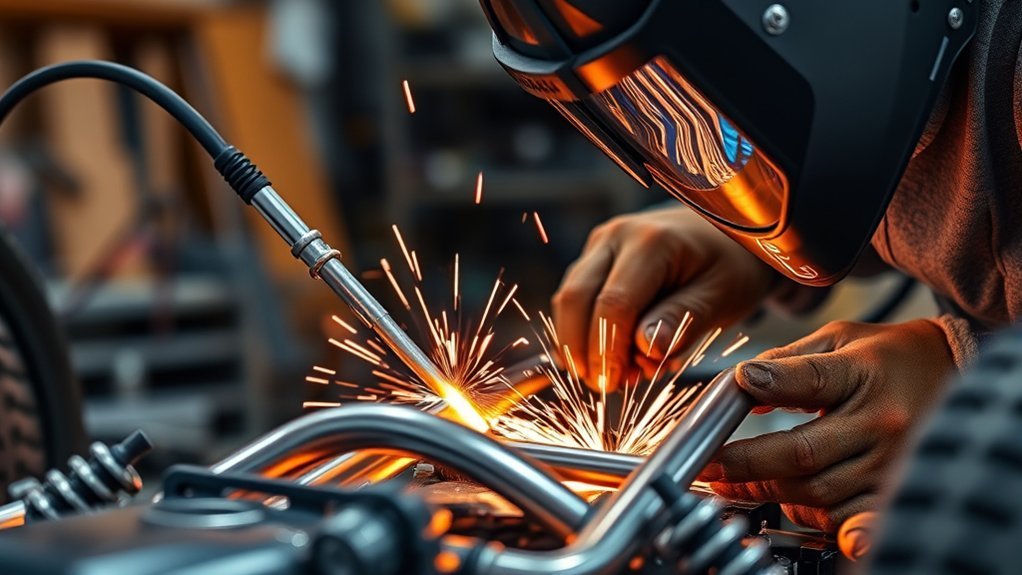
Welding a tubular chassis for racing is structural fabrication, not a casual welding project. Your goal is to build a straight, rule-compliant frame with clean tube fit-up, controlled heat, strong welds, and documented inspection. Start with the class rulebook, a proven chassis plan, and the correct tubing specification before you cut or weld anything.
Quick Answer
To weld a tubular chassis, confirm the racing rulebook first, choose approved tubing, build on a rigid jig, notch every tube for tight fit-up, tack the frame square, then MIG or TIG weld with a qualified procedure. Inspect every joint for cracks, porosity, undercut, and alignment before finishing or painting.
Key Takeaways
- Start with your sanctioning-body rulebook, not a generic tubing or gusset thickness.
- Good chassis welds depend on fit-up first: accurate cuts, clean metal, tight notches, and controlled gaps.
- MIG can work well on many mild-steel chassis builds, while TIG gives more control on thin-wall or chromoly work when allowed.
- Use tack sequencing, cross-measurements, and heat control to prevent twist, shrinkage, and misalignment.
- Do not over-grind structural welds. Inspect and document weld quality before primer or powder coat hides defects.
At a Glance
| Time Required | Several days to several weeks, depending on chassis complexity, jig setup, bends, notching, welding, and inspection |
| Difficulty | Advanced; structural welding experience, measuring accuracy, and rulebook knowledge are required |
| Tools Needed | Rulebook, chassis plan, jig table, tube bender, tubing notcher, saw or cutoff tool, deburring tools, clamps, squares, angle finder, level, MIG or TIG welder, PPE, ventilation, and inspection tools |
| Cost | Varies widely by tubing material, class rules, tooling, welder qualification, fixture needs, and inspection requirements |
Warning: A racing chassis is a safety-critical structure. Follow the current rulebook for your class, use approved materials and welding methods, and have the work inspected by a qualified fabricator, engineer, or sanctioning-body inspector before competition use.
What You Need to Know Before Designing a Tubular Chassis
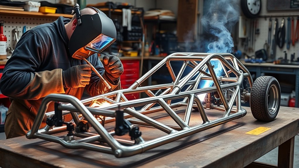
Before you design a tubular chassis, identify the racing class, vehicle weight, engine location, suspension layout, driver position, and inspection rules. Current competition organizations publish rulebooks and technical regulations for vehicle safety, so the first step is always compliance, not cutting tube. Review the latest rules from your series, such as the SCCA General Competition Rules resources, NASA rules resources, or the FIA regulations library, depending on where the car will run.
A strong chassis uses clear load paths. Tubes should meet at nodes wherever possible, especially around suspension mounts, engine mounts, roll-over protection, seat mounts, harness mounts, and impact zones. Avoid ending tubes in the middle of unsupported spans unless the design has reinforcement there. Triangulation matters because triangles resist flex better than open rectangles.
Plan the chassis around access, too. You need room to notch, tack, and weld completely around the tube joints. If a joint becomes hidden before final welding, you may create an unwelded or under-welded area that is hard to inspect later. Good planning also leaves room for pedals, steering, fuel lines, brake lines, exhaust, cooling, fire system, seat, belts, and future service work.
Fillet weld size, weld length, tube wall thickness, and gusset placement must work together. Use class rules or engineering guidance for critical connections, and review proper fillet weld sizing when you are designing brackets, tabs, and gusseted joints.
Choosing the Best Materials for Your Tubular Chassis
Choosing the right material can make or break your chassis. Do not treat “steel tube” as one universal product. Many race builds use mild-steel DOM or CDS tubing because it is predictable, weldable, and widely accepted in many rulebooks. Some higher-end chassis use 4130 chromoly, but chromoly requires more careful welding control, filler selection, heat management, and inspection.
Use the tubing diameter, wall thickness, and material grade required by your class rules. If the rulebook gives a minimum tube size, do not reduce it for weight savings. If your design adds load beyond the original rule intent, such as heavier engine output, aero loads, off-road impacts, or suspension changes, get engineering input before finalizing the layout.
Gusset plates and filler panels also need context. A gusset is structural when it reinforces a node, bracket, suspension mount, or cage intersection. A filler panel may be non-structural if it only closes a gap or mounts bodywork. Do not assume one gauge works everywhere. Match the plate thickness, weld size, and base material to the load and the rulebook.
Note: Keep material certificates, tubing invoices, filler-wire labels, and rulebook notes with the build file. Inspectors may ask what material was used and how the chassis was welded.
For brackets and panels, accurate cutting matters. A saw, abrasive cutoff wheel, shear, or plasma cutter can work depending on the part. A plasma cutter is useful for plate and tab work when it is set up correctly, and a well-matched cutter can improve cutting accuracy and efficiency. Clean all cut edges before welding.
Top Tools You Need for Tubing Fabrication
When fabricating a tubular chassis, the right tools help you hold repeatable dimensions and reduce rework. The main tools fall into four groups: measuring tools, cutting and notching tools, bending tools, and welding/holding tools.
Products Worth Considering
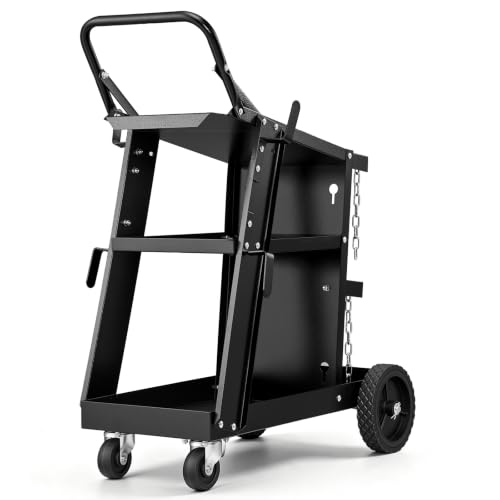
Strong Weight Capacity: VEVOR 3-tier welding cart can effortless handle various heavy loads, with 400LBS maximum static weight capacity and 370LBS maximum dynamic weight capacity. Heavy-duty welder cart is suitable for a variety of welding tasks such as manual welding, gas shielded welding, and argon arc welding.

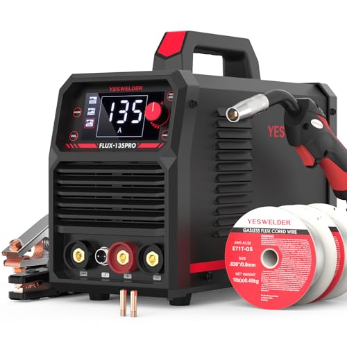
READY OUT OF THE BOX: Start welding immediately! It masterfully handles Gasless Flux Core MIG, Stick, and Lift TIG (Extra Lift TIG torch required). This budget-friendly 3-in-1 machine includes extra E71T-GS .030''&.035'' flux core wires, known for its smooth arc and high feedability. Say goodbye to heavy shielding gas cylinders—perfect for outdoor, windy, or all-position welding.
Essential Welding Equipment
A MIG welder is often used on mild-steel chassis work because it is fast, productive, and practical for many tube-wall thicknesses. A TIG welder gives more control over heat, puddle placement, and filler addition, especially on thin-wall tubing, chromoly work, or visible joints. The best choice depends on the material, rulebook, weld procedure, and welder skill.
You also need shielding gas, correct filler wire or rod, a clean ground connection, suitable amperage range, and a way to test settings on scrap from the same tubing. Never tune the welder for the first time on the chassis itself. Cut coupons from the same tube size and practice tack welds, lap joints, and notched joints before moving to the frame.
Safety equipment is part of the tool list. OSHA states that helmets or hand shields must be used during arc welding or arc cutting, and welding can produce hazardous fumes and gases that require adequate ventilation. Use a welding helmet, gloves, flame-resistant clothing, hearing protection, eye protection for grinding, and fume control that fits the work area.
Measurement and Alignment Tools
Measurement tools keep the chassis square. Use a tape measure, steel rule, digital caliper, angle finder, machinist square, magnetic square, plumb bob, centerline string, and level. A flat jig table or frame bench is strongly preferred because it lets you hold datum points and check diagonals throughout the build.
| Tool | Purpose | Why It Matters |
|---|---|---|
| Digital caliper | Checks tube OD, wall, and bracket thickness | Confirms material matches the plan |
| Tube bender | Forms controlled bends | Prevents crushed or wrinkled tubing |
| Tubing notcher | Cuts fishmouth joints | Improves fit-up and weld consistency |
| Jig table and clamps | Holds chassis geometry | Reduces twist during tacking and welding |
Measuring and Cutting Tubing: A Step-by-Step Guide
Accurate measuring and cutting start with a drawing, CAD model, full-size layout, or proven chassis plan. Do not use a random “standard” tube length. Every tube length depends on the distance between nodes, bend tangent points, bend allowance, notch depth, and final trim allowance.
Products Worth Considering

Mini cylindrical level small horizontal bubble levels 9.5x40mm bubble spirit level measuring layout tools.

Measures Threaded Pipe sizes 1/8 to 2in Measures Tubing sizes 1/8 to 1in Measures Hose ID sizes 1/4 to 1in

Acrylic Construction:Made from durable acrylic material, ensuring clarity and precision. The transparent design allows for easy visibility of the bubble, enhancing accuracy.
Accurate Measurement Techniques
Use this workflow before cutting any main tube:
- Mark a chassis centerline and fixed datum points on the jig table.
- Confirm tube size, wall thickness, and material against the rulebook and plans.
- Measure from node to node, not just outside-to-outside tube edges.
- Mark bend start, bend centerline, rotation angle, and tube orientation.
- Add conservative trim allowance when notching complex joints.
- Label each tube before it leaves the bench.
Check both sides of the chassis against the same datum. A small measuring error on the left side and another on the right side can add up to a twisted frame. Use diagonal measurements often, especially around suspension pickup points and cage intersections.
Precision Cutting Methods
Cut tubing with a horizontal band saw, cold saw, abrasive saw, or cutoff wheel that can hold the tube securely. Before using a cutoff wheel, check the tool, guard, wheel condition, and speed rating. A detailed cutoff wheel process can help you avoid crooked cuts and unsafe setup, especially when you inspect your cutting tool before starting.
After each cut, deburr the inside and outside edges. Remove oil, mill scale, paint, rust, and marker residue from the weld zone. A clean edge helps the tack weld start smoothly and reduces the risk of porosity.
How to Notch and Fit Tubing Before Welding
Tube notching is where many chassis welds succeed or fail. A good fishmouth notch wraps around the mating tube with even contact and a small, controlled gap. A poor notch leaves large gaps that force the weld to bridge empty space, raising heat input and reducing consistency.
Use a hole-saw notcher, belt notcher, mill, grinder, or carefully controlled hand tools. Test-fit often. The tube should sit in the correct rotation and angle without clamp force pulling it into place. If the tube springs away when unclamped, the notch or bend is wrong.
Pro Tip: Sneak up on the final notch. Leave the tube slightly long, test-fit it, mark the high spots, then trim slowly until the joint sits naturally in the jig.
How to Bend Tubing Accurately
Accurate bends require more than pulling the handle on a bender. You need the correct die for the tubing diameter, the correct bend radius, a known springback value, and repeatable tube orientation. Mark the bend start, bend centerline, and rotation line before loading the tube.
Follow these bending practices:
- Use the bender manufacturer’s instructions for minimum bend radius and die setup.
- Make a test bend from the same tubing before bending critical chassis tubes.
- Record springback so repeated bends match the drawing.
- Keep the tube indexed so bends rotate in the correct plane.
- Reject tubing that wrinkles, flattens, kinks, or thins beyond acceptable limits.
Preload and clamp pressure matter because loose clamping can let the tube slip, while excessive force can mark or distort the tubing. Check the angle during the bend, then check it again after release because springback can change the final angle.
If you are working with galvanized or coated parts near the chassis, remove coatings from the weld area and control fumes. Welding galvanized steel can create zinc oxide fumes, so understand zinc fumes before any hot work near coated metal.
How to Align Tubing for Maximum Strength
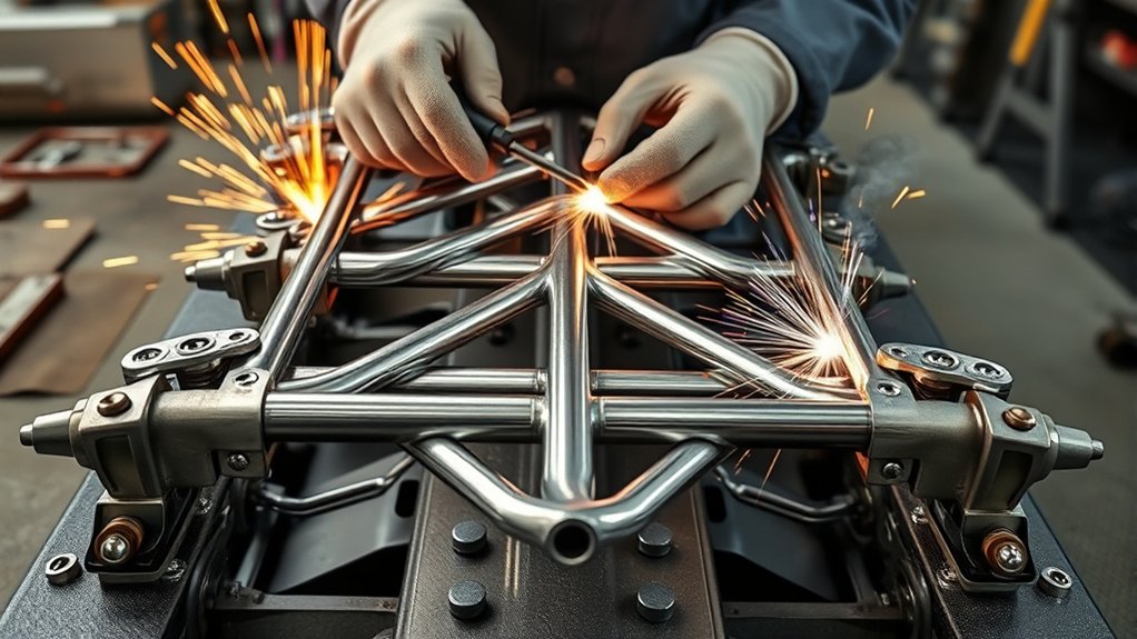
Strong chassis alignment starts with a rigid fixture. Bolt or clamp main rails, bulkheads, suspension mounts, and cage nodes to known datum points. Keep the frame level, but do not rely on a bubble level alone. Cross-measure, plumb down to the table, and verify the chassis against the drawing.
Proper Tubing Positioning
Position each tube so it lands at a node whenever possible. The strongest chassis joints usually connect multiple tubes at a shared point instead of spreading forces across an unsupported tube span. When adding braces, aim for direct load paths from suspension, engine, seat, harness, and roll-over loads into the surrounding structure.
Use temporary supports during fitting so tubes do not sag before tacking. Do not pull a tube into alignment with a heavy clamp and then weld it under stress. Once the clamp is removed, that stored tension can move the chassis.
Consistent Angle Checks
Check angles during fitting, after tacking, and after each major welding sequence. A tube can move after only a few tack welds. Measure diagonals across rectangular openings, compare left and right suspension pickup points, and keep notes so you know when the chassis began to move.
Preload Settings Importance
Preload is useful in a tube bender, but it should not be used as a shortcut for forcing the chassis into shape. In fabrication, controlled clamping holds parts at the correct datum. Excessive clamping hides fit-up problems and may create stress in the finished frame.
If zinc, paint, plating, or primer is present near a joint, strip it before welding. Removing zinc coatings and other surface contamination helps protect the weld pool and reduces fume risk.
Joining Tubing: Welding Techniques and Alternatives
When you weld a tubular chassis, choose the process that matches the material, rulebook, wall thickness, and welder qualification. MIG and TIG can both produce strong welds when used correctly, but neither process guarantees a safe chassis by itself.
MIG welding is common for mild-steel DOM or CDS chassis work because it is efficient and practical on many tube joints. Use the right wire, shielding gas, polarity, and voltage/wire-speed settings. Test on scrap first, cut and inspect practice welds, and confirm penetration without excessive burn-through.
TIG welding gives precise puddle control and can be preferred for thin-wall tubing, chromoly applications, or high-visibility joints. TIG also makes it easier to control filler addition around complex fishmouth joints. However, TIG demands clean material, steady fit-up, and strong skill. Follow the rulebook and any required welding procedure.
For shielding and heat settings, make sure your setup matches the base metal and filler. A settings guide such as shielding gas flow information can help you think through gas coverage, but chassis welds still need material-specific setup and testing.
Warning: Do not weld sealed tube sections without venting. OSHA requires hollow spaces, cavities, or containers to be vented before preheating, cutting, or welding. Vent holes also reduce pressure buildup and help trapped gases escape.
Assembling Your Tubular Chassis: Key Steps
Assembly should move from stable reference points to smaller braces and tabs. Build the main structure first, then add secondary tubes, brackets, tabs, and panels after the frame is square.
- Set the jig: Mark centerline, axle lines, wheelbase, suspension pickup points, and floor height.
- Fit the main tubes: Cut, bend, notch, deburr, and clean the main rails and primary structure.
- Tack lightly but securely: Use enough tack welds to hold alignment, but leave room for correction.
- Cross-measure: Check diagonals, height, side-to-side symmetry, and tube rotation.
- Add braces: Fit triangulation tubes so they land cleanly at nodes.
- Review access: Make sure every joint can be fully welded before closing sections.
- Final weld in sequence: Alternate sides and locations to balance heat and shrinkage.
Large tack welds can hold the assembly, but they should not hide poor fit-up. If a tube moves during tack welding, stop and correct the fit before final welding. Clean metal surfaces are essential because rust, oil, paint, and mill scale can create poor weld quality and weak-looking beads.
Controlling Heat and Distortion
Heat shrinkage can pull a tubular chassis out of square. Even a clean weld shrinks as it cools. If every weld is made on one side of the chassis before the opposite side is welded, the frame can twist.
Use a balanced weld sequence. Move around the chassis, weld opposing joints, and allow hot sections to cool naturally. Do not quench structural welds with water. Re-check the chassis after major weld groups and before adding brackets that depend on exact alignment.
Common heat-control habits include:
- Use tight fit-up so you do not overfill gaps.
- Set the welder on scrap of the same material before final welding.
- Keep the arc length short and consistent.
- Use stitch sequencing only when the design and procedure allow it.
- Let the jig hold the chassis until the welded structure cools.
Fit-up controls weld quality. If the joint is clean, tight, square, and stress-free before welding, you need less heat and less filler to make a sound joint.
Finishing Your Welds: Cleaning and Preparation Tips
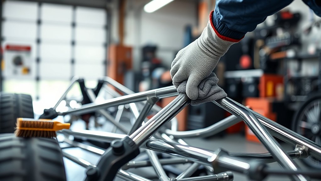
After welding, let the chassis cool naturally while still supported. Then inspect before grinding, coating, or covering anything. A weld that will be hidden by primer, seam sealer, powder coat, or body panels must be checked first.
Use a wire brush, scraper, or light abrasive only to remove spatter, slag, discoloration, and surface contamination. Do not grind structural welds flush unless the design, rulebook, or inspector specifically allows it. Grinding can remove throat thickness and hide undercut, cracks, or lack of fusion.
If rust is present on non-critical loose parts before fabrication, remove it fully before welding. Vinegar can dissolve light oxide on small parts, but it is not a substitute for proper joint preparation on chassis tubing. When using chemical cleaning methods, understand how vinegar affects oxide bonds, then rinse, dry, and mechanically clean the weld area before hot work.
After inspection, protect exposed metal with a compatible rust-inhibiting primer or coating. Avoid coating inside areas that still need welding, and do not trap moisture in tube openings.
Inspection and Quality Control Before Racing
Inspection is not optional on a race chassis. At minimum, perform a visual inspection of every joint after final welding and cooling. For competition work, follow the inspection process required by your sanctioning body and consider professional non-destructive testing for critical joints.
Look for these problems:
- Porosity: pinholes or gas pockets in the weld bead.
- Undercut: a groove along the toe of the weld that reduces base-metal thickness.
- Incomplete fusion: bead sits on the surface without bonding properly to the tube.
- Excessive convexity or cold lap: bead is too piled up and may not have fused at the edges.
- Cracks: any crack is a stop-and-repair issue.
- Distortion: suspension points, cage points, or engine mounts no longer match the drawing.
Document the final chassis with photos before coating. Record tubing material, wall thickness, filler metal, process, shielding gas, and inspection notes. This helps with future repairs and gives inspectors a clearer record of the build.
Troubleshooting Common Tubular Chassis Issues
Most chassis problems trace back to planning, fit-up, heat sequence, or cleaning. Fix the cause before re-welding the same joint.
| Problem | Likely Cause | Fix |
|---|---|---|
| Tube joint has a large gap | Poor notch or wrong tube angle | Re-notch or replace the tube; do not bridge wide gaps with weld |
| Frame pulls out of square | Unbalanced weld sequence or weak jigging | Re-check datum points, clamp correctly, and weld opposing joints in sequence |
| Porosity in welds | Dirty metal, poor gas coverage, wind, or wrong settings | Grind out the defect, clean the joint, fix shielding, and re-weld only if allowed |
| Burn-through | Too much heat, wide gap, or thin-wall tube | Improve fit-up, reduce heat input, and test settings on scrap |
| Grinding damage | Wrong disc, excessive pressure, or poor access | Use the correct abrasive and verify the wheel speed rating before grinding |
Frequently Asked Questions
What are the disadvantages of a tubular chassis?
A tubular chassis can be expensive, time-consuming, and difficult to repair after a hard crash. It also requires accurate jigging, approved materials, skilled welding, and inspection. If the design lacks triangulation or uses poor welds, it may be lighter but not safer.
What type of welding is best for a tubular chassis?
The best welding process depends on the tubing material, wall thickness, rulebook, and welder skill. MIG is common for many mild-steel DOM chassis builds. TIG gives more heat and filler control, especially on thin-wall tubing or chromoly work. Use the process approved by your class rules and welding procedure.
Which metals are difficult or unsuitable for MIG welding?
MIG can weld many steels and aluminum with the right equipment, wire, gas, and technique, but some metals are difficult or unsuitable without special procedures. Cast iron, some high-carbon steels, titanium, magnesium, and many dissimilar-metal combinations require specialized processes and should not be treated like mild steel chassis tubing.
What welder should I use for chassis welding?
Use a welder with enough output control for your tube wall thickness, stable arc performance, correct shielding gas setup, and compatibility with the required filler. For mild steel, a quality MIG or TIG machine can work. For chromoly or thin-wall precision work, TIG is often preferred, but rulebook approval and welder skill matter more than the machine label.
Should chassis welds be ground smooth?
Usually, no. Grinding structural welds can reduce weld throat and hide defects. Only smooth a weld if the rulebook, design, or inspector allows it. Remove spatter and sharp edges, but leave structural weld profiles visible for inspection whenever possible.
Can I weld a racing chassis at home?
You can fabricate at home only if you have the skill, tools, space, ventilation, fire controls, and inspection path required for structural work. For a competition chassis, get the design and welds reviewed by a qualified fabricator or inspector before the car is used on track.
Conclusion
Welding a tubular chassis is about precision, compliance, and safety. Start with the rulebook, build from accurate datum points, fit every tube tightly, keep the metal clean, and use a welding process that matches the material and procedure. A good chassis is not proven by pretty welds alone. It is proven by correct design, controlled fabrication, careful inspection, and approval before it reaches the track.
Sources
- OSHA 1910.252 General Requirements — welding fire prevention, PPE, ventilation, and hollow-space venting guidance.
- OSHA Welding, Cutting, and Brazing Overview — hazards, standards, and safety resources for welding operations.
- NIOSH Welding Fumes and Manganese — welding fume composition, manganese exposure, and health risk context.
- SCCA Cars and Rules — current competition rulebook resources and technical compliance context.
- NASA Rules Resources — current racing rules and class-specific competition requirements.
- FIA Regulations Library — downloadable international sporting and technical regulations.