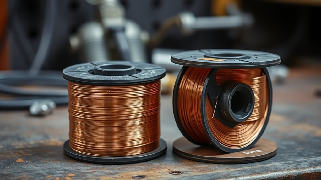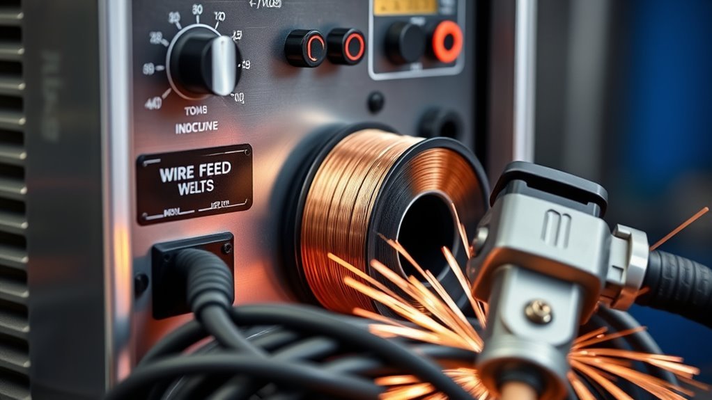
A wire feed welder depends on a complete wire path, not just a motor and a pair of rollers. The spool hub, drive system, wire guides, gun liner, contact tip, shielding-gas parts, and work connection all affect how steadily the wire reaches the arc. When you match, clean, and adjust these parts correctly, you get smoother feeding, more stable starts, and fewer weld defects.
Quick Answer
The main wire feed welder parts are the spool hub, feeder motor, drive rolls, wire guides, gun liner, contact tip, gas diffuser and nozzle, shielding-gas system, trigger controls, and work clamp. Smooth feeding depends on matching each part to the wire, using light tension, keeping the wire path clean, and replacing worn consumables.
What’s in This Article
- Understanding MIG Welding Fundamentals
- Key Components of a MIG Wire Feeder System
- How Wire Travels Through the Feeder
- Drive Rollers: Role and Maintenance Tips
- How the Feeder Motor Ensures Consistent Wire Delivery
- Wire Spool Hubs: Impact on Welding Efficiency
- How Liners Keep Your Wire Feeding Smoothly
- Wire Feeder Contact Tips: Maintenance Essentials
- Gas System, MIG Gun, and Work Clamp
- Wire Feeder Maintenance Checklist
- Wire Feed Troubleshooting Chart
- Signs It’s Time to Replace Wire Feeder Parts
- Choosing Quality MIG Wire Feeder Components
- Frequently Asked Questions
- Conclusion
- Sources
Key Takeaways
- Match the drive-roll groove, liner range, contact-tip size, and wire guides to the electrode diameter and type.
- Use only enough drive-roll and spool-brake tension to feed smoothly without slipping, crushing the wire, or letting the spool overrun.
- Keep the gun cable as straight as practical and clean the liner only by the method and pressure allowed in your manual.
- Replace worn tips, kinked liners, grooved rolls, damaged guides, and cracked gun cables before they create repeated birdnesting or burnback.
- Check gas flow and the work connection separately because a bad arc can look like a feeding problem even when wire speed is steady.
At a Glance
| Time Required | About 10 to 20 minutes for a basic inspection and cleaning |
| Difficulty | Beginner for consumable care; qualified service may be needed for motor or control faults |
| Tools Needed | Owner’s manual, safety glasses, side cutters, clean brush, lint-free cloth, and dry compressed air only if the manual permits it |
| Cost | Usually none for inspection; replacement-part cost varies by welder, gun, and wire size |
Understanding MIG Welding Fundamentals
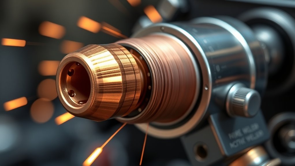
Gas metal arc welding (GMAW), commonly called MIG welding, uses a continuously fed consumable wire electrode and shielding gas to join metal. The contact tip transfers welding current to the moving wire, and the arc forms between that energized wire and the workpiece.
The name MIG originally means metal inert gas. However, many steel setups use carbon dioxide or an argon and carbon dioxide blend, so GMAW is the more accurate umbrella term. In everyday shop language, people still use MIG for most gas-shielded wire welding.
The wire feeder sends electrode wire from the spool to the gun at a controlled speed. In a constant-voltage GMAW setup, wire feed speed strongly affects welding current, while voltage helps control arc length and bead shape. Stable feeding helps the power source maintain a steady arc.
Shielding gas protects the molten weld pool from the surrounding air. Mild steel often uses carbon dioxide or an argon and carbon dioxide blend. Aluminum commonly uses argon. Stainless-steel gas selection depends on the wire, transfer mode, material, and procedure.
Clean base metal, correct polarity, suitable gas flow, and a solid work connection help prevent porosity, lack of fusion, and unstable starts. Use extra care when MIG welding galvanized steel because heating zinc coatings can produce hazardous fumes.
Gas-shielded MIG welding can join mild steel, stainless steel, and aluminum when the machine, wire, gas, gun, and consumables suit the job. Self-shielded flux-cored wire also uses a wire feeder, but it may not need an external gas cylinder.
Warning: Welding can expose you to electric shock, hot metal, ultraviolet radiation, fire, and hazardous fumes. Disconnect input power before opening the feeder, close the gas cylinder when servicing gas parts, wear proper PPE, and use ventilation that meets your workplace rules and the machine manufacturer’s instructions.
Key Components of a MIG Wire Feeder System
A MIG wire feeder system contains more than the visible drive rolls. Every part from the spool to the contact tip must stay aligned and low in resistance. The gas system and work circuit do not push the wire, but they directly affect arc quality and can confuse troubleshooting.
| Part | What It Does | Common Problem |
|---|---|---|
| Wire spool and hub | Stores the wire and controls spool rotation | Too much drag or spool overrun |
| Feeder motor and gearbox | Turns the drive rolls at the set speed | Surging, stalling, noise, or no movement |
| Drive rolls | Grip and push the electrode wire | Slipping, crushing, shaving, or misalignment |
| Inlet and outlet guides | Keep the wire centered through the drive system | Wire snagging or birdnesting |
| Gun liner | Guides wire through the gun cable | Drag from dirt, kinks, wrong size, or poor trimming |
| Contact tip | Guides the wire and transfers welding current | Burnback, keyholing, poor electrical pickup, or binding |
| Gas diffuser and nozzle | Distribute and direct shielding gas | Spatter blockage or gas leakage |
| Trigger and control circuit | Commands wire feed, gas flow, and welding output | Intermittent response or no feed |
| Gas regulator, hose, and solenoid | Control and deliver shielding gas | No flow, leaks, contamination, or poor coverage |
| Work lead and clamp | Complete the welding circuit through the workpiece | Popping arc, heat, voltage drop, or no arc |
The drive rolls and feeder motor control wire movement, but they cannot overcome a blocked liner, tight tip, bent gun cable, or excessive hub tension. Regular checks on drive-roll tension and the full wire path help prevent slipping, birdnesting, and uneven feeding.
Essential Drive Rollers
Drive rolls grip the wire and move it toward the gun. The groove must match both the wire diameter and the wire type. A correct roll gives enough traction without flattening soft wire or cutting debris from the electrode surface.
Feeder Motor Functionality
The feeder motor powers the drive rolls through a gearbox. A healthy motor should respond smoothly when you change wire feed speed. Surging can come from the motor or control board, but resistance elsewhere in the wire path is more common and should be checked first.
How Wire Travels Through the Feeder
- The spool hub releases wire. Brake tension prevents the spool from coasting after the motor stops.
- The inlet guide centers the wire. It should line up with the drive-roll groove without rubbing.
- The drive rolls push the wire. Roll type, groove size, alignment, and pressure all matter.
- The outlet guide supports the wire. A large gap before the liner can let soft wire buckle and birdnest.
- The liner carries wire through the gun cable. Dirt, kinks, sharp bends, and poor trimming add drag.
- The contact tip guides and energizes the wire. The opening must match the wire and remain round enough for steady current transfer.
- The nozzle directs shielding gas around the arc. Gas coverage protects the weld pool but does not feed the wire.
A steady arc starts with a clean, correctly sized, low-resistance wire path from the spool to the contact tip.
Drive Rollers: Role and Maintenance Tips
Drive rolls affect how consistently your welder feeds wire. If they slip, wear, collect debris, or fail to match the electrode, the arc can become unstable even when the voltage and wire speed settings are correct.
Inspect the roll surface, groove, alignment, and pressure before long jobs. Small feed problems often start here, especially after a wire-size change. These checks also apply when fixing model-specific problems such as Hobart welder wire-feed issues.
Drive Roller Types
The three common drive-roll styles are V-groove, U-groove, and knurled:
- V-groove rolls: Common for solid steel and stainless-steel wire.
- U-groove rolls: Support softer wire, especially aluminum, without concentrating pressure on a sharp edge.
- Knurled rolls: Provide extra grip for many flux-cored wires. Excessive pressure can still distort tubular wire.
Always confirm the groove and size markings against the wire and your welder manual. Some machines use combination rolls with more than one groove.
Maintenance Best Practices
- Disconnect input power before opening the feeder or touching internal parts.
- Remove loose wire dust with a clean, dry brush or the method approved in the manual.
- Look for polished flat spots, deep grooves, rust, packed metal shavings, and damaged bearings.
- Confirm that the inlet guide, roll groove, outlet guide, and liner entrance form a straight path.
- Start with low roll pressure, then increase it only until the wire feeds without slipping.
- Do not use extra roll pressure to force wire through a dirty liner or blocked contact tip.
Common Feeding Issues
Watch for slipping, birdnesting beside the drive rolls, changing motor sound, inconsistent arc sound, and sudden burnback. These signs tell you to inspect the complete path rather than turning up the pressure immediately.
Miller notes that overtightened drive rolls can deform wire, while dirty, damaged, or incorrectly installed liners and contact tips can create similar feed problems.
Check simple causes first: straighten the gun cable, remove the contact tip, trim damaged wire, inspect the guides, clean the rolls, and test whether the wire moves freely through each section. Do not keep increasing tension because too much pressure can make the problem worse.
Pro Tip: When you change wire diameter or type, treat the rolls, guides, liner, contact tip, polarity, and gas as one setup. Changing only the spool often leaves one mismatched part in the feed path.
How the Feeder Motor Ensures Consistent Wire Delivery
The feeder motor turns the rolls that pull wire from the spool and push it through the gun. Smooth motor speed supports a stable arc, but the motor should not have to fight excessive spool drag, a crushed wire, a dirty liner, or a blocked tip.
If the motor surges, slows, or stalls, the arc may pop and wander. You may also see extra spatter, poor starts, or an uneven bead. Before blaming the motor, release drive-roll pressure and check whether the spool turns correctly and whether the wire path is free.
Set voltage and wire feed speed for the material, thickness, wire size, joint, position, and transfer mode. Correct settings cannot compensate for dirty or mismatched feeder parts.
Keep the feeder compartment clean and dry. Inspect visible wiring and plugs for looseness, heat damage, or abrasion, but do not open sealed motor, gearbox, or control assemblies unless the manual allows it and you are qualified to service them.
Grinding, electrical smells, repeated overheating, no speed response, or a motor that runs only when tapped can point to worn brushes, gear damage, a failing control board, or a bad connection. At that stage, use a qualified service technician.
Poor gas flow or a weak work connection can make the arc unstable even when wire speed is steady. Check those systems separately so you do not replace a working motor.
Wire Spool Hubs: Impact on Welding Efficiency
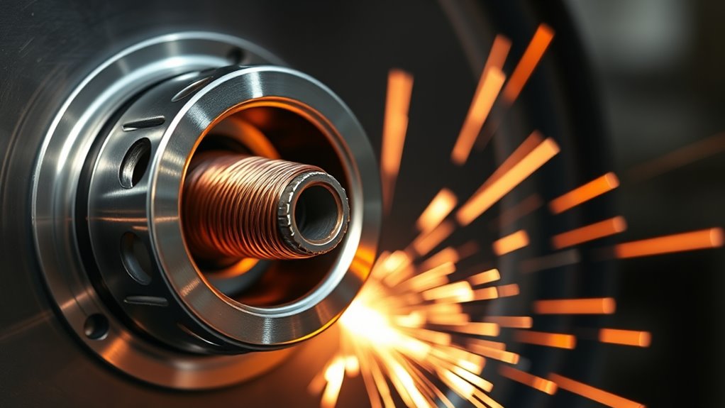
The spool hub holds the electrode spool and applies braking drag. If the hub is too tight, the motor must pull harder and wire speed may fall or surge. If it is too loose, the spool can coast after you release the trigger and create loose loops or tangles.
Install the spool in the feed direction shown in the manual. Keep control of the wire end because springy electrode wire can uncoil quickly. Route the wire through the guides without letting it scrape the feeder case.
| Factor | Effect | Recommended Action |
|---|---|---|
| Hub fit | Controls spool alignment and rotation | Use the correct adapter, retaining hardware, and orientation |
| Brake tension | Prevents drag or overrun | Use only enough tension to stop coasting, following the manual |
| Spool condition | Affects smooth unwinding | Replace damaged spools and keep wire clean, dry, and rust-free |
| Inspection frequency | Finds drag before welding starts | Check installation and rotation whenever you load wire |
Pro Tip: Set the hub brake by the procedure in your manual. The spool should not coast into loose loops after wire feeding stops, but it should turn without making the motor strain.
How Liners Keep Your Wire Feeding Smoothly
The liner guides electrode wire from the feeder through the gun cable to the contact tip. A clean, correctly sized, correctly trimmed liner reduces drag and keeps wire movement steady.
A dirty, kinked, undersized, oversized, or badly trimmed liner can cause wire drag, poor starts, birdnesting, and an unstable arc. Rust, copper flakes, metal shavings, and shop dust can collect inside it over time.
Miller identifies liner wear, kinks, incorrect sizing, and improper trimming as common causes of feeding problems. The same source recommends compressed-air cleaning, but you should follow your specific gun manual for direction, pressure, disassembly, and safety precautions.
Before cleaning, disconnect power, remove the wire as directed, remove the contact tip when required, lay the gun cable straight, and wear eye protection. Use only clean, dry air if the manufacturer permits it. Replace the liner when cleaning no longer restores smooth feeding or when you find kinks, crushed sections, severe wear, or damaged ends.
Match the liner range and material to the electrode. Steel liners commonly guide steel wire. Aluminum often needs a liner and feed system designed for soft wire, along with U-groove rolls and low drive pressure. Many aluminum setups use a spool gun or push-pull gun to shorten the distance that soft wire must travel.
Keep the gun lead as straight as practical while welding. Tight loops and sharp bends increase friction. Good liner care supports a consistent MIG wire feed and helps prevent spatter, burnback, and downtime.
Wire Feeder Contact Tips: Maintenance Essentials
Contact tips guide the wire and transfer welding current to it. The tip opening must suit the electrode size and application. A tip that is too tight can bind the wire, while an oversized or worn opening can reduce electrical pickup and make the arc wander.
Spatter can block the tip face or fuse the wire to the tip during burnback. Turn off the machine before changing consumables. Use the cleaning method approved by the gun manufacturer, and do not enlarge the bore with a drill bit or an improvised tool.
Replace the tip when you see an oval or enlarged opening, repeated burnback, poor starts, visible heat damage, loose threads, or an arc that becomes unstable after the rest of the feed path checks out. Miller describes this oval wear as keyholing and links it to irregular electrical pickup and extra spatter.
Inspect the gas diffuser and nozzle at the same time. The diffuser supports the contact tip and distributes gas. The nozzle directs gas around the weld pool. Remove spatter without damaging threads, insulation, or gas holes.
Contact-tip care matters with solid and flux-cored wire. When using flux-core welding, also account for slag, wire type, polarity, and the possibility of self-shielded operation.
Gas System, MIG Gun, and Work Clamp
Shielding-Gas Parts
A gas-shielded setup normally includes a cylinder, regulator or flowmeter, hose, gas solenoid, gun passages, diffuser, and nozzle. Compressed air is not MIG shielding gas. Use the gas and flow range specified for the electrode and welding procedure.
If gas does not flow, check the cylinder valve, regulator setting, hose kinks, fittings, solenoid action, diffuser holes, and nozzle. Use an approved leak-checking method. Never use an open flame to find a gas leak.
MIG Gun, Trigger, and Cable
The gun carries wire, welding current, trigger signals, and shielding gas. Inspect the handle, neck, cable jacket, strain relief, connector, trigger, and power-pin area. A damaged cable can add wire drag, interrupt current, or leak gas.
An intermittent trigger may point to a damaged switch, plug, control lead, or connection. If the wire feeds with a jog control but not with the gun trigger, inspect the trigger circuit before replacing the feeder motor.
Work Lead and Clamp
The part commonly called a ground clamp is more accurately the work clamp. It completes the welding circuit through the workpiece. Attach it to clean metal close to the weld when practical, and inspect the cable, jaws, lugs, and connections for looseness, corrosion, or heat damage.
A poor work connection can cause a weak, popping, or intermittent arc, but it does not usually change the mechanical wire speed. That distinction helps separate an electrical arc problem from a true feeding problem.
Wire Feeder Maintenance Checklist
- Make the machine safe. Turn off and disconnect input power. Close the gas cylinder when servicing gas components. Follow lockout procedures in a workplace.
- Inspect the spool and hub. Check spool condition, wire cleanliness, retaining hardware, feed direction, and brake tension.
- Inspect the drive system. Check roll type, size, groove condition, alignment, pressure, and guide position.
- Straighten and inspect the gun cable. Look for tight bends, crushed areas, cuts, heat damage, and loose connections.
- Check the liner. Clean it only by the manual’s method. Replace it if kinked, worn, incorrectly sized, or repeatedly troublesome.
- Inspect front-end consumables. Check the contact tip, diffuser, insulator, and nozzle for wear, spatter, loose fit, and blocked gas passages.
- Check gas and work connections. Look for leaks, restrictions, loose fittings, damaged hoses, and a dirty or weak work-clamp connection.
- Reload and test safely. Keep hands away from the drive rolls and point the gun away from your body while feeding wire. Test on scrap before returning to the job.
Note: Maintenance intervals vary with wire type, environment, duty cycle, and equipment design. Inspect more often in dusty shops, when using rusty or dirty wire, or after repeated feed faults. Your owner’s manual takes priority over a general schedule.
Practical Maintenance Schedule
- Before each use: Check wire condition, spool mounting, drive-roll pressure, gun cable, contact tip, nozzle, gas supply, and work clamp.
- At each spool or wire change: Confirm roll, guide, liner, tip, polarity, and gas compatibility. Remove loose debris from the feeder.
- When feed quality changes: Inspect the full path immediately instead of compensating with more pressure.
- Periodically: Clean internal areas, inspect cables and hoses, and service motor or control parts only as the manufacturer directs.
Wire Feed Troubleshooting Chart
| Symptom | Likely Causes | What to Check |
|---|---|---|
| Wire slips at the rolls | Low pressure, wrong groove, worn roll, excessive downstream drag | Roll markings, groove condition, alignment, liner, tip, hub tension |
| Birdnesting near the feeder | Blocked liner or tip, large guide gap, wrong roll, too much pressure, soft wire buckling | Remove damaged wire, free the path, align guides, reduce pressure |
| Erratic or surging feed | Dirty liner, spool drag, worn rolls, loose connections, motor or control fault | Isolate each section of the path before testing the motor |
| Burnback into the tip | Wire stopped, tip blocked, feed too slow for the voltage, poor tip condition | Replace the damaged tip, restore smooth feed, verify settings |
| Motor turns slowly or strains | Hub too tight, liner drag, excessive roll pressure, low supply voltage, motor fault | Remove mechanical resistance first, then seek service if the fault remains |
| Wire feeds but there is no arc | Open work circuit, bad gun connection, contactor or power-source fault | Use the checks in this wire-feeds-but-no-arc guide and the machine manual |
| Arc is unstable but feed looks steady | Worn tip, poor work clamp, wrong polarity, gas problem, dirty metal, bad settings | Separate electrical, gas, and setup checks from mechanical feed checks |
| Spool uncoils after release | Hub brake too loose or spool mounted incorrectly | Reset hub tension and verify retaining parts |
Signs It’s Time to Replace Wire Feeder Parts
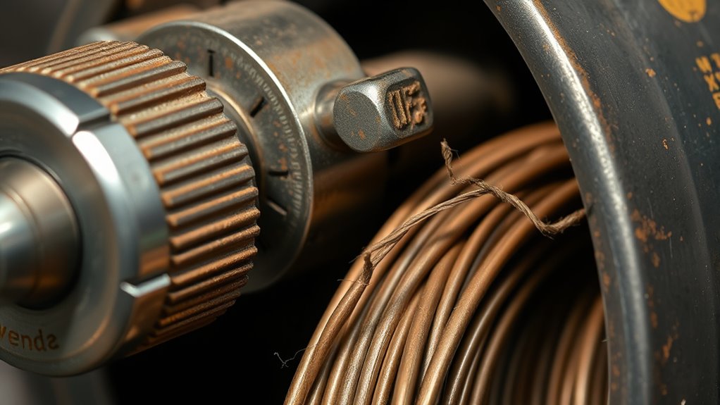
You can often spot worn wire feeder parts before they fail completely. Pay attention to how the welder sounds, how the wire moves, how the trigger responds, and how the arc starts.
- Drive rolls: Replace rolls with deep wear, damaged grooves, flat spots, cracked surfaces, or bearings that do not turn smoothly.
- Wire guides: Replace guides that are worn open, burred, cracked, or impossible to align close to the rolls.
- Liner: Replace it when correct cleaning does not fix drag, or when it is kinked, crushed, badly trimmed, contaminated, or the wrong size.
- Contact tip: Replace it after burnback, keyholing, thread damage, repeated poor starts, or unstable electrical contact.
- Gun cable or trigger: Replace or repair cracked jackets, damaged strain reliefs, gas leaks, hot spots, intermittent trigger action, or broken conductors.
- Spool hub parts: Replace damaged adapters, retaining hardware, or brake parts that cannot hold a stable adjustment.
- Feeder motor or gearbox: Seek service for persistent grinding, surging, overheating, loss of torque, or no speed control after the wire path is cleared.
Irregular wire feed can come from worn rolls, a blocked liner, incorrect hub tension, or a failing drive system. Birdnesting near the rolls usually points to downstream resistance, poor guide alignment, or excessive pressure. Excessive spatter, poor starts, and burnback often point to the contact tip or an interruption in wire movement.
Regular inspection of the feeder, gun, gas parts, and work circuit can prevent many failures before they damage a weld or stop a job.
Products Worth Considering

Scope Of Application: Welding auxiliary machine is suitable for 0.8/1.0mm welding wire, suitable for welding in industry, woodworking and equipment, with fast and smooth wire feeding
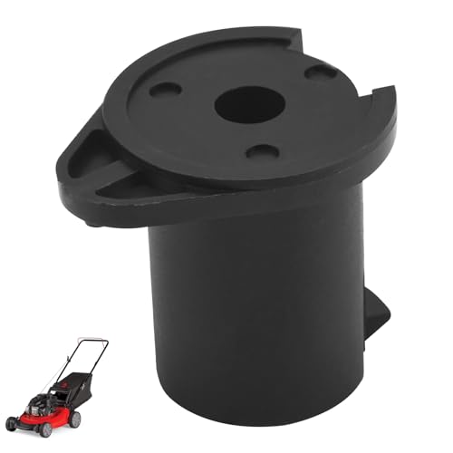
Replace Part Number: M15445-1 M15445 KH720 M15445-R

Choosing Quality MIG Wire Feeder Components
Choose parts that match the welder, feeder, gun, wire type, wire diameter, polarity, and duty requirements. Correct fit matters more than a low purchase price.
The best replacement part is the one that matches the complete feed system, not merely the one that looks similar.
- Drive rolls: Match the groove style and marked size to the electrode.
- Wire guides: Confirm diameter range, shape, mounting style, and alignment.
- Feeder motor: Use the correct voltage, speed range, connector, gearbox, and control design for the exact model.
- Liner: Match wire material, diameter range, gun model, and gun length. Follow the specified trimming method.
- Contact tip: Match the wire and gun system. Consider application heat and access, not just bore size.
- Gas diffuser and nozzle: Use compatible threads, insulation, gas passages, and nozzle geometry.
- Technical support: Prefer suppliers that provide manuals, parts diagrams, fitment help, and warranty support.
Do not choose parts by price alone. A poorly fitting roll, liner, guide, or tip can waste wire, gas, consumables, and troubleshooting time. When in doubt, use the machine serial number and gun model to confirm fitment.
Products Worth Considering

COMPATIBILITY: Designed for Lincoln Magnum 100L (K530 series) and Tweco Mini/#1 welding torches. This kit is also a direct fit for YESWELDER FLUX-135PRO Old Version/MIG-140DS PRO/YWM-160/MIG-165DS PRO/MIG-185DS PRO/MIG-205DS PRO/MIG-250PRO/MCT-520.

【Dual Fit Spool Holder】This spool stand assembly is designed for both 1KG and 5KG reels, providing convenient compatibility for MIG welding machines.
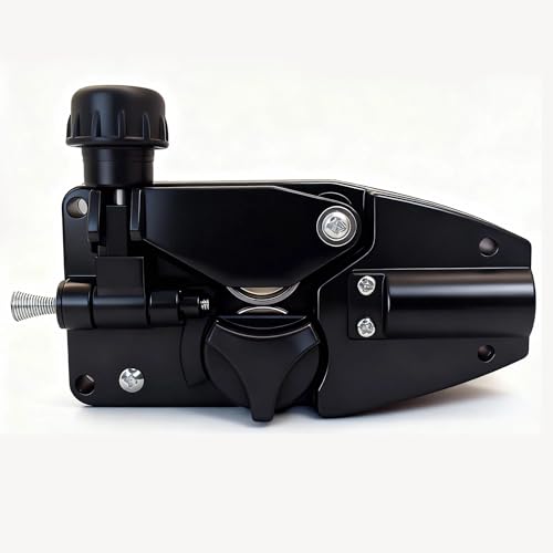
Package List :1pcs Drive Motor(12V or 24V DC 10W Mig Welder Wire Feed Motor Mig Wire Motor Mig Wire Feeder)
Frequently Asked Questions
What are the main parts of a wire feed welder?
The main parts are the power source, wire spool and hub, feeder motor, drive rolls, wire guides, gun liner, MIG gun, contact tip, gas diffuser, nozzle, trigger controls, shielding-gas system, and work lead with clamp. Self-shielded flux-cored setups may not use an external gas system.
What are the 7 parts of a welding machine?
There is no universal seven-part list because welding machines differ. A simple MIG system can be grouped into a power source, wire feeder, welding gun, electrode supply, shielding-gas system, controls, and work circuit. Each group contains smaller service parts such as rolls, guides, a liner, a tip, and a nozzle.
What do 1F, 2F, 3F, and 4F mean in welding?
They identify fillet-weld positions: 1F is flat, 2F is horizontal, 3F is vertical, and 4F is overhead. The number comes before the letter. These labels describe weld position, not wire-feeder control functions.
Can you make $100,000 a year welding?
It is possible, but it is not typical wage-only pay for the occupation as a whole. The U.S. Bureau of Labor Statistics reported a $51,000 median annual wage in May 2024, with the highest 10 percent above $75,850. Reaching $100,000 may involve specialized work, overtime, travel, hazardous locations, supervision, contracting, or self-employment.
How often should you replace a MIG liner?
Replace a MIG liner based on condition rather than a fixed calendar. Change it when approved cleaning no longer fixes drag, jams, or poor starts, or when it is kinked, crushed, contaminated, incorrectly sized, or badly trimmed. High wire usage and dirty environments shorten liner life.
Why does my MIG wire keep birdnesting?
Birdnesting usually means the drive rolls are pushing against resistance. Common causes include a blocked or kinked liner, a damaged contact tip, poor guide alignment, an oversized gap before the liner, the wrong drive roll, excessive pressure, or soft wire being pushed through a long or sharply bent cable.
Why does the wire slip even when the feeder motor is turning?
The rolls may have too little pressure, the wrong groove, poor alignment, packed debris, or worn surfaces. The wire may also face too much resistance from a tight spool hub, bent cable, dirty liner, wrong liner size, or blocked contact tip. Fix the resistance instead of only tightening the rolls.
Can I use the same liner and drive rolls for aluminum wire?
Do not assume the steel setup will work. Aluminum is soft and usually needs U-groove rolls, low pressure, a liner approved for aluminum, and a short, straight feed path. Many machines use a spool gun or push-pull gun. Follow the exact recommendations for your welder, gun, wire alloy, and diameter.
Conclusion
Your MIG wire feeder works best when every part supports smooth wire movement. Start with the simple checks: spool mounting, hub tension, roll type and pressure, guide alignment, gun-cable position, liner condition, contact tip, gas flow, and work connection.
Clean and inspect these parts regularly, and replace worn consumables before they create repeated feed faults. When the wire path is clean and correctly matched but the motor still grinds, surges, overheats, or loses speed control, stop troubleshooting at the consumable level and arrange qualified service.
Sources
- American Welding Society: What Is GMAW? – supports the process definition, continuous electrode feed, and shielding-gas role.
- Lincoln Electric: Drive-Roll Types – supports V-groove, U-groove, and knurled roll selection.
- Miller: Wire-Feeder Myths and Feedability – supports troubleshooting of overtightened rolls, liners, and contact tips.
- Miller: MIG Consumables and Maintenance – supports liner sizing, liner care, contact-tip wear, diffusers, and nozzles.
- OSHA 29 CFR 1910.252 – supports welding-fume, ventilation, and general safety guidance.
- U.S. Bureau of Labor Statistics: Welders, Cutters, Solderers, and Brazers – supports the wage context in the FAQ.