
Welding position changes how gravity acts on the molten weld pool, so a technique that works in the flat position may sag, undercut, or trap slag when you move vertical or overhead. This guide explains the standard plate and pipe welding positions, how to read their codes, and how to adjust your angle, travel, filler metal, and process without replacing the requirements of an approved welding procedure specification.
Quick Answer
The four basic plate welding positions are flat, horizontal, vertical, and overhead. Groove welds use 1G through 4G, while fillet welds use 1F through 4F. As gravity becomes harder to manage, use a smaller weld pool, steadier travel, position-rated filler metal, and the settings required by your WPS.
Key Takeaways
- Flat welding is usually the easiest place to learn because the work supports the molten pool.
- Horizontal, vertical, and overhead welds require tighter control of heat, pool size, arc length, and travel speed.
- G means groove weld, while F means fillet weld; plate and pipe use some different position numbers.
- Vertical-up and vertical-down are not interchangeable. Follow the approved WPS, code, and filler-metal instructions.
- The complete electrode or wire classification must permit the intended position.
- Clean fit-up, stable body position, correct PPE, ventilation, and careful inspection prevent many common defects.
At a Glance
| Time Required | About 15–30 minutes per practice coupon; consistent skill requires repeated sessions. |
| Difficulty | Beginner for flat practice; intermediate to advanced for vertical, overhead, and fixed pipe. |
| Tools Needed | Welder, position-rated filler metal, clean practice coupons, clamps, cleaning tools, measuring tools, full PPE, and suitable fume control. |
| Cost | Varies by process; practice costs mainly include metal coupons, electrodes or wire, shielding gas, cleaning supplies, and PPE. |
What’s in This Article
- Introduction to Welding Positions: Why They Matter
- What Are the Four Basic Welding Positions?
- How to Read Welding Position Codes
- Work Angle vs. Travel Angle
- Understanding Flat Welding Position Techniques (1G/1F)
- Horizontal Welding Challenges and Techniques (2G/2F)
- Vertical Welding Positions: Uphill vs. Downhill Techniques (3G/3F)
- How to Tackle Overhead Welding With Better Control (4G/4F)
- Common Pipe Welding Positions: 1G, 2G, 5G, and 6G
- The Role of Filler Metal in Welding Positions
- How Welding Position Affects Process Choice
- How to Practice Welding Positions
- Avoiding Common Mistakes in Welding Positions
- Safety Rules for Every Welding Position
- Frequently Asked Questions
- Conclusion
- Sources
Introduction to Welding Positions: Why They Matter
Understanding welding positions helps you control the weld pool, bead profile, penetration, fusion, and slag. Flat, horizontal, vertical, and overhead welding each place the joint at a different angle to gravity.
The flat position usually gives a beginner the best view and the most stable pool. Overhead welding places the welder below the joint, where molten metal, sparks, and slag can fall toward the body.
Position knowledge also affects filler metal selection. Some wires and electrodes are designed for all-position welding, while others are limited to flat or horizontal work. Proper fillet weld sizing also matters because a larger-than-needed weld can add heat, time, weight, and distortion without improving the joint.
Position codes appear on welding procedure specifications, filler-metal data sheets, qualification records, and training materials. The American Welding Society maintains standardized terminology through AWS A3.0M/A3.0.
Note: General technique advice does not replace an approved welding procedure specification. The WPS controls permitted process, position, filler metal, polarity, parameter range, joint design, direction of progression, preheat, and other essential details for code work.
What Are the Four Basic Welding Positions?
The four basic plate-welding categories are flat, horizontal, vertical, and overhead. Groove welds commonly use the codes 1G, 2G, 3G, and 4G. Fillet welds use 1F, 2F, 3F, and 4F.
The position code describes the orientation of the test joint. It does not, by itself, tell you every production position for which a welder is qualified. Qualification ranges depend on the governing code, test type, process, material, thickness, diameter, backing, and other variables.
| Position | Plate Codes | How Gravity Acts | Common Problems | Control Priority |
|---|---|---|---|---|
| Flat | 1G / 1F | Supports the pool in the joint | Excess buildup, overlap, burn-through | Steady travel and correct heat |
| Horizontal | 2G / 2F | Pulls the pool toward the lower edge | Sagging, overlap, upper-edge undercut | Small pool and balanced work angle |
| Vertical | 3G / 3F | Pulls molten metal downward | Undercut, slag traps, excessive convexity | Pause at the toes and cross the center quickly |
| Overhead | 4G / 4F | Pulls the pool and sparks toward the welder | Sagging, drop-through, poor tie-in, burns | Short arc, small pool, stable posture |
How to Read Welding Position Codes
The number describes the position, and the letter describes the joint type. For common plate tests:
- 1 means flat.
- 2 means horizontal.
- 3 means vertical.
- 4 means overhead.
- G means a groove weld.
- F means a fillet weld.
A 2G test is therefore a horizontal groove weld. A 3F test is a vertical fillet weld. Pipe uses additional designations because the pipe may rotate, remain fixed, or sit at an incline.
A position code identifies the test-joint orientation. The applicable code and qualification record determine what production welding that test permits.
Work Angle vs. Travel Angle
Welders often say “torch angle” or “electrode angle,” but two separate angles are involved:
- Work angle is the side-to-side angle between the electrode and the joint. A symmetrical T-joint fillet often starts near a 45-degree work angle because the heat must reach both members.
- Travel angle is the forward or backward tilt measured in the direction of travel. The correct travel angle depends on the process, filler metal, position, joint, and whether the procedure calls for a push or drag technique.
Do not apply one 45-degree recommendation to every joint. Groove bevels, unequal thicknesses, lap joints, and out-of-position welds may need the heat aimed more toward one side.
Pro Tip: Watch both toes of the weld instead of staring only at the arc. The edges show whether the pool is tying into the base metal or beginning to undercut, overlap, or sag.
Understanding Flat Welding Position Techniques (1G/1F)
In the flat welding position, the work supports the molten pool. This lets you concentrate on joint fit-up, arc length, work angle, travel angle, speed, and bead placement without fighting gravity as much as you do in other positions.
Clean the joint before welding and use only guards, wheels, brushes, and discs approved for the grinder and its rated speed. Review this angle-grinder safety guidance before fitting unapproved cutting accessories.
Key Techniques for Flat Welding
Keep the arc length or contact-tip-to-work distance within the range recommended for your process. Sudden changes alter heat, shielding, penetration, and bead width.
Use an appropriate work angle for the joint. For an equal T-joint fillet, a work angle near 45 degrees is a common starting point. Center a groove weld so heat reaches both sides of the joint.
Set travel speed by watching the pool. Moving too slowly can create a wide, highly convex bead or burn-through. Moving too fast can leave a narrow bead with undercut, incomplete fusion, or incomplete penetration.
MIG/GMAW, TIG/GTAW, stick/SMAW, and flux-cored/FCAW processes can all be used in the flat position when the procedure and consumable permit them.
Common Flat Welding Mistakes
| Mistake | Likely Result | Correction |
|---|---|---|
| Changing arc length or stickout | Uneven bead, spatter, unstable heat | Brace your hands and maintain a consistent distance |
| Traveling too slowly | Excess buildup, overlap, distortion, or burn-through | Increase travel speed within the approved parameter range |
| Traveling too quickly | Undercut, narrow bead, or poor fusion | Slow down and confirm adequate heat input |
| Welding contaminated metal | Porosity, inclusions, unstable arc, weak bonding | Remove oil, moisture, rust, paint, and loose scale as the procedure permits |
Essential Safety Precautions
Flat welding may feel controlled, but it still produces ultraviolet radiation, fumes, sparks, hot metal, noise, and electrical hazards.
- Protect your eyes and face: Wear safety glasses under a welding helmet fitted with a suitable filter shade.
- Cover exposed skin: Use flame-resistant clothing, welding gloves, suitable boots, and process-appropriate head and hearing protection.
- Control fumes and fire hazards: Use suitable ventilation or local exhaust, remove or shield combustible material, and keep the work area dry and orderly.
Warning: A welding helmet does not replace safety glasses, ventilation, protective clothing, or fire controls. Follow the equipment manual, facility rules, and applicable safety requirements every time.
Horizontal Welding Challenges and Techniques (2G/2F)
In the horizontal welding position, gravity draws molten metal toward the lower side of the joint. A horizontal groove weld, or 2G, usually gives the pool less support than a 2F fillet, where the lower plate acts as a shelf.
Use a controlled pool rather than a wide, fluid weave. Stringer beads often make it easier to manage heat and prevent the lower edge from rolling over.
On a horizontal groove, you may need to aim the work angle slightly toward the upper edge so both sides fuse while gravity pulls the pool downward. Watch the lower toe for overlap and the upper toe for undercut.
Excessive heat can make the pool sag. Insufficient heat or very fast travel can leave incomplete fusion. Change only one variable at a time and remain within the approved parameter range.
Pro Tip: If a horizontal bead sags, first reduce the size and fluidity of the pool. Simply racing ahead may create undercut or incomplete fusion.
Vertical Welding Positions: Uphill vs. Downhill Techniques (3G/3F)
Vertical welding may progress upward or downward. The correct direction depends on the process, material, joint, filler metal, service requirements, and WPS.
- Vertical-up: Common on thicker joints where controlled sidewall fusion and greater fill are needed. The welder supports the pool by pausing at each toe and moving more quickly across the center.
- Vertical-down: Often used for selected thinner-material or pipeline applications because it can reduce heat input and increase travel speed. It must not be substituted when the WPS requires upward progression.
- Pool control: Keep the pool small enough to support. Use only the stringer or weave technique permitted by the procedure.
For vertical-up practice, watch each edge of the pool. Pause long enough for the toe to fill, then cross the center before the pool becomes too large. A wide, slow weave can trap slag or create excessive buildup.
For vertical-down practice, maintain the correct leading position over the pool and avoid outrunning the arc. Fast travel without adequate fusion can produce a smooth-looking bead that does not bond fully.
Adjust voltage, amperage, wire feed speed, arc length, and travel only within the approved range. Basic home welding safety precautions also help you maintain a stable working position.
Note: “Vertical-up is strong” and “vertical-down is weak” are oversimplifications. Either direction can produce an acceptable weld when the process, joint, filler metal, parameters, and procedure are designed and qualified for it.
How to Tackle Overhead Welding With Better Control (4G/4F)
Overhead welding places you beneath the joint. Gravity pulls the molten pool, sparks, and slag toward the welder, so body position and pool size become critical.
Set up so you can complete the pass without stretching, twisting, or losing sight of the joint. Brace yourself when possible while keeping your head away from the direct fall line of sparks and slag.
Maintain the arc length, stickout, work angle, and travel angle recommended for the process. A compact pool and controlled stringer beads are usually easier to manage than a wide weave.
Good overhead welding starts before the arc: secure the work, clear your escape path, cover exposed skin, and confirm that you can reach the whole joint without losing balance.
Use the approved amperage, voltage, polarity, electrode diameter, and travel range. Do not reduce heat so far that fusion suffers. Careful stick-welder settings guidance can provide a starting point, but the electrode data sheet and WPS take priority.
Practice short beads before attempting a long overhead joint. Stop and reposition if your posture, view, or control begins to deteriorate.
Warning: Wear flame-resistant clothing that closes at the neck and cuffs, suitable gloves, boots, a welding cap, and eye and face protection. Hot metal can collect in open pockets, cuffs, footwear, or ears.
Common Pipe Welding Positions: 1G, 2G, 5G, and 6G
Pipe-position codes describe both the pipe axis and whether the pipe rotates. Fixed pipe forces the welder to change technique while moving around the circumference.
| Pipe Position | Pipe Orientation | Rotation | What the Welder Experiences |
|---|---|---|---|
| 1G | Pipe axis horizontal | Pipe rotates | The arc stays near the top, allowing welding mainly in the flat position |
| 2G | Pipe axis vertical | Pipe remains fixed | The groove is welded horizontally around the pipe |
| 5G | Pipe axis horizontal | Pipe remains fixed | The welder moves through flat, vertical, and overhead areas |
| 6G | Pipe fixed at an incline, commonly about 45 degrees in qualification testing | Pipe remains fixed | The angle changes continuously around the joint, combining several difficult orientations |
The 6G configuration is widely regarded as one of the most demanding common qualification tests because the welder must adjust position, angle, speed, and pool control around the fixed pipe. However, the exact test setup and qualification range depend on the governing code.
Do not assume that passing one position automatically qualifies every process, material, thickness, diameter, progression direction, or joint. Read the qualification record and applicable code.
The Role of Filler Metal in Welding Positions
Your filler metal must match the process, base metal, joint design, mechanical requirements, shielding method, polarity, and position. A wire or electrode that works well in flat welding may produce an uncontrollable pool or unsuitable slag behavior overhead.
In common AWS flux-cored classifications such as E70T-XX and E71T-XX, the position digit provides useful guidance:
- 0 commonly indicates use in flat groove welds and flat or horizontal fillet welds.
- 1 commonly indicates all-position capability.
That digit is not the whole specification. Read the complete classification, manufacturer data sheet, diameter limitations, usability designator, shielding-gas requirement, polarity, and WPS before welding out of position. The correct flux-core wire can improve pool support, slag release, deposition rate, and bead profile.
Filler Metal Position Suitability
- Check the position rating: Confirm that the exact wire or electrode permits the planned position and progression direction.
- Check the process requirements: Verify polarity, shielding gas, flow range, stickout or arc length, and recommended parameters.
- Check diameter restrictions: A product family may be all-position, but larger diameters may be limited or harder to control out of position.
- Check storage and condition: Damp, rusty, contaminated, or damaged consumables can cause porosity, hydrogen problems, unstable arcs, and poor slag behavior.
How Filler Metal Specifications Affect Weld Quality
| Filler Metal or Process | General Position Guidance | What to Verify |
|---|---|---|
| E70T-XX flux-cored classification | The zero commonly indicates flat groove and flat or horizontal fillet use | Complete classification, diameter, gas, polarity, and data sheet |
| E71T-XX flux-cored classification | The one commonly indicates all-position capability | Vertical progression, diameter, usability designator, and WPS |
| Stick electrode | Position depends on the complete electrode classification | Position digit, polarity, storage, diameter, and procedure |
| TIG filler rod | Can be used in multiple positions with suitable technique | Alloy match, shielding, joint cleanliness, heat input, and procedure |
How Welding Position Affects Process Choice
Welding position influences which process and transfer mode will give you a controllable pool. The table below provides general guidance, not a substitute for a qualified procedure.
| Process or Transfer Mode | General Position Capability | Main Consideration |
|---|---|---|
| TIG/GTAW | All positions with suitable technique | Precise heat, torch, filler, and shielding control |
| Short-circuit MIG/GMAW | Generally all positions | Good pool control, but inadequate parameters can cause lack of fusion on thicker joints |
| Conventional spray-transfer MIG | Normally flat and horizontal | The hot, fluid pool is difficult to support vertically or overhead |
| Pulsed MIG | Can support all-position welding | Requires compatible equipment, wire, gas, program, and procedure |
| Stick/SMAW | Depends on electrode classification | Arc length, slag behavior, electrode angle, and diameter |
| Flux-cored/FCAW | Depends on wire classification and diameter | Slag support, stickout, heat, shielding, and position rating |
Spray transfer is not the same as pulsed spray. Conventional spray uses a continuously hot, fluid arc and is normally suited to flat and horizontal welding. Pulsed MIG lowers average heat and can make out-of-position welding possible when the system and procedure are designed for it.
Products Worth Considering
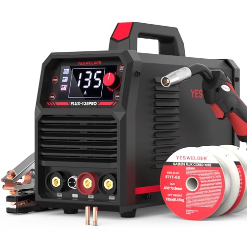
READY OUT OF THE BOX: Start welding immediately! It masterfully handles Gasless Flux Core MIG, Stick, and Lift TIG (Extra Lift TIG torch required). This budget-friendly 3-in-1 machine includes extra E71T-GS .030''&.035'' flux core wires, known for its smooth arc and high feedability. Say goodbye to heavy shielding gas cylinders—perfect for outdoor, windy, or all-position welding.

7 in 1 Welding Machine: The multi-function welding machine included Gas/Solid Wire MIG,Pulse MIG, Gasless Flux Core MIG, Stick/MMA, Spot welding, Lift TIG, spool gun compatible (tig gun and spool gun not included,WP-17V-35,LBT150).

9-IN-1 WELDER:ARCCAPTAIN MIG205MP MIG welder has 9 welding modes: Gas MIG/Gasless MIG/Cut/DC HF TIG/DC Lift TIG/MMA Stick/Clean/Spot Welding/Spool Gun Aluminum Welding (Need to buy extra spool gun). This multiprocess welder perfectly handles all your needs—from home DIY and garage projects to outdoor repairs, farm equipment, and road maintenance and repairs.
How to Practice Welding Positions
Prepare the Practice Joint
- Choose the same material, thickness, joint, process, and filler metal you expect to use.
- Clean the joint and surrounding area as required by the procedure.
- Check the root opening, root face, bevel angle, alignment, and tack welds.
- Secure the coupon so it cannot move, tip, or fall.
- Confirm polarity, gas type, gas flow, consumable condition, and machine settings.
- Arrange cables and hoses so they do not pull your hand or create a trip hazard.
- Make a test bead and adjust only within the permitted parameter range.
Follow a Skill Progression
- Flat beads: Learn arc starts, stops, speed, distance, and bead overlap.
- Flat fillets and grooves: Add joint fit-up and sidewall fusion.
- Horizontal joints: Learn to balance heat between the upper and lower edges.
- Vertical-up and approved vertical-down joints: Practice pool support and toe control.
- Overhead joints: Develop a small pool, short controlled arc, and stable body position.
- Fixed pipe: Move to 2G, 5G, or 6G only after individual plate positions are consistent.
Inspect Every Practice Weld
Let the coupon cool safely, remove slag as required, and inspect it under good lighting. Check:
- Bead width and consistency
- Smooth tie-in at both toes
- Undercut or overlap
- Porosity and visible inclusions
- Excessive convexity or reinforcement
- Cracks, craters, and poor restarts
- Distortion and fit-up movement
- Root penetration when the joint design allows inspection
A visually attractive bead is not proof of internal fusion or mechanical strength. Code work may require bend tests, radiography, ultrasonic testing, macroetch testing, or another specified examination.
Avoiding Common Mistakes in Welding Positions
Position-related defects often begin with poor access, unstable posture, inconsistent fit-up, unsuitable filler metal, or parameters copied from another position.
| Symptom | Possible Causes | What to Check |
|---|---|---|
| Pool sags or rolls downward | Too much heat, pool too large, slow travel, wrong position-rated consumable | Parameter range, bead size, angle, progression, and filler data sheet |
| Undercut at the upper toe | Excess heat, poor work angle, travel too fast, insufficient toe pause | Aim, travel speed, pool width, voltage, and amperage |
| Overlap at the lower toe | Pool too cold or large, poor angle, slow travel | Fusion at the lower edge, heat input, and bead placement |
| Slag inclusion | Inadequate cleaning, poor bead shape, excessive weave, wrong angle | Clean between passes and keep slag behind the pool |
| Porosity | Contamination, moisture, drafts, gas loss, long arc, blocked nozzle | Surface condition, consumables, gas system, nozzle, arc length, and wind protection |
| Lack of fusion | Heat too low, travel too fast, poor angle, oversized pool hiding the leading edge | WPS range, joint access, work angle, speed, and pool visibility |
| Uneven bead | Unstable posture, changing arc length, cable drag, poor visibility | Body position, hand support, lens condition, lighting, and cable placement |
Inspect the joint before striking the arc. Remove oil, moisture, rust, paint, loose scale, and other contaminants using methods allowed by the procedure.
Coated metals require additional precautions. Welding galvanized steel can release zinc-containing fumes, and removing a small strip of coating does not eliminate every exposure. Review safe preparation and ventilation requirements before welding galvanized steel.
Safety Rules for Every Welding Position
Welding hazards do not disappear when the bead looks easy. The Occupational Safety and Health Administration identifies metal fumes, ultraviolet radiation, burns, eye damage, electrical shock, and other hazards associated with welding and cutting.
Wear Complete PPE
- Safety glasses with side protection under the welding helmet
- A helmet and filter shade suitable for the process and current
- Flame-resistant clothing that covers exposed skin
- Dry welding gloves in good condition
- Suitable boots without open tops that collect sparks
- Hearing protection when noise or falling sparks create an ear hazard
- A welding cap or other suitable protection for overhead work
Control Fumes and Coatings
Use suitable general ventilation or local exhaust to keep fumes away from your breathing zone. Respiratory protection may be required after a proper hazard assessment, especially for confined spaces, coated metal, stainless steel, lead, cadmium, beryllium, or other hazardous materials.
Do not use oxygen for ventilation. Keep chlorinated cleaning vapors away from the welding area, and identify unknown coatings before heating them.
Prevent Fire and Explosion
Remove combustible material or protect it with suitable fire-resistant barriers. Keep sparks from entering wall openings, floor cracks, ducts, or hidden spaces. Provide a fire watch when required.
Never weld a used drum, tank, pipe, fuel container, or closed cavity merely because it appears empty. Such items may contain flammable residue or toxic vapors and require approved cleaning, isolation, venting, testing, and work procedures.
Treat Confined Spaces as Specialized Work
A tank, vessel, boiler, or other restricted space can contain a hazardous atmosphere and can make rescue difficult. Confined-space welding may require atmospheric testing, forced ventilation, equipment outside the space, an attendant, a rescue plan, and a permit program. Do not enter without the required training and controls.
Warning: Stop welding if you smell an unknown coating, feel dizzy or ill, lose ventilation, see a fire outside the controlled area, detect damaged cables, or cannot maintain a safe body position. Shut down the equipment and correct the hazard before continuing.
Frequently Asked Questions
What safety gear is essential for each welding position?
Wear safety glasses under a welding helmet with a suitable shade, flame-resistant clothing, dry welding gloves, and suitable boots. Add hearing and head protection when needed. Use proper ventilation or local exhaust, and follow any respiratory-protection requirements identified for the material and work area.
How does welding position affect joint strength and integrity?
Position changes pool behavior, heat distribution, penetration, fusion, bead shape, and slag movement. A qualified procedure can produce sound welds in any approved position, but poor control may cause undercut, overlap, incomplete fusion, incomplete penetration, porosity, or slag inclusions.
Can I switch positions during a welding project?
Yes, when the joint geometry requires it and the procedure permits it. Adjust your body position, work angle, travel angle, speed, and pool control as the joint orientation changes. Do not change process, progression direction, filler metal, or parameters outside the WPS.
What tools are best suited for different welding positions?
Use secure clamps, fixtures, positioners, measuring tools, a wire brush, chipping tools when slag is present, and process-approved grinding equipment. Choose a power source and position-rated filler metal that match the material, joint, and WPS. Good lighting and cable management also improve control.
How do I practice each welding position effectively?
Begin with flat beads, then practice flat joints, horizontal welds, vertical welds, and overhead welds. Use consistent coupons and record the process, filler metal, settings, angle, and result. Inspect every bead before changing a variable. Move to fixed pipe only after the individual plate positions are repeatable.
Which welding position is hardest to learn?
Overhead is often the hardest of the four basic plate positions because the welder works below the joint while gravity pulls the pool and sparks downward. Fixed 6G pipe is commonly considered even more demanding because the welding angle changes continuously around the inclined pipe.
What is the difference between 3G-up and 3G-down?
In 3G-up, welding progresses from the bottom toward the top and commonly uses controlled pauses to support the pool and fuse both sides. In 3G-down, welding progresses from the top toward the bottom and often uses faster travel. Use only the direction allowed by the WPS and filler-metal classification.
What is the difference between 1G and 5G pipe welding?
In 1G pipe welding, the pipe rotates so the welder can keep the arc near the top in a favorable position. In 5G, the pipe remains fixed with its axis horizontal, forcing the welder to move through flat, vertical, and overhead portions of the joint.
Conclusion
Welding positions matter because each orientation changes access, gravity, pool behavior, heat control, and slag movement. Begin with flat welding, then progress through horizontal, vertical, and overhead joints after your fit-up, arc length, angles, and travel become consistent.
Before every weld, confirm the position, joint, approved WPS, filler-metal classification, polarity, shielding, parameter range, progression direction, and safety controls. Practice deliberately, inspect each bead, and correct one variable at a time. That approach builds stronger position skills than copying a single angle or machine setting.
Sources
- American Welding Society — AWS A3.0M/A3.0:2025 — current standardized welding terminology and test-position context.
- American Welding Society — How to Pass a Welding Test — WPS use, qualification terminology, defects, inspection, and 6G pipe guidance.
- Miller Electric — The Four Basic Welding Positions — plate positions, work angles, filler-metal position digits, and general process suitability.
- Miller Electric — Welding Process and Transfer-Mode Selection — short-circuit, spray, pulsed MIG, and position capabilities.
- OSHA — Welding, Cutting, and Brazing Hazards and Solutions — fume, radiation, burn, eye, electrical, and PPE hazards.
- OSHA 29 CFR 1910.252 — fire prevention, eye protection, protective clothing, ventilation, coated metals, containers, and confined-space requirements.




