
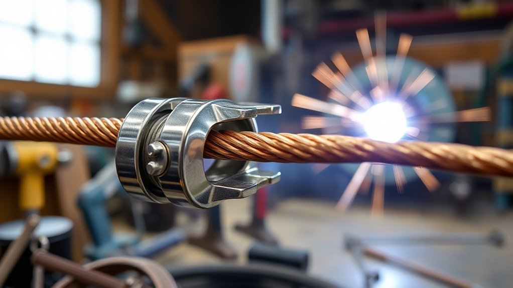
A welding ground clamp—more accurately called a work clamp—connects the workpiece to the welding power source so welding current has a controlled return path. Clean metal contact, firm clamping pressure, correct cable sizing, and careful placement all affect arc performance. This guide explains how the clamp works, where to attach it, how to troubleshoot it, and how to choose a suitable replacement.
Quick Answer
A welding ground clamp, properly called a work clamp, connects the workpiece to the welder’s output circuit. Attach it firmly to clean, bare metal near the weld. A dirty, loose, damaged, or undersized connection can cause difficult arc starts, an unstable arc, voltage loss, excessive heat, and inconsistent welding performance.
Key Takeaways
- “Ground clamp” is the common shop term, but work clamp is more accurate because the clamp is part of the welding-current circuit.
- The work clamp is not a replacement for the welding machine’s protective equipment-grounding conductor.
- Attach the clamp to clean, bare metal on the workpiece or a proven conductive fixture near the weld.
- Keep welding current out of chains, hoists, bearings, hinges, electronics, and other unintended paths.
- Choose the clamp and lead by amperage, duty cycle, total circuit length, connector size, and the welder manufacturer’s instructions.
- Stop welding if the clamp, connector, or cable becomes unusually hot.
At a Glance
| Time Required | About 1–3 minutes for inspection, cleaning, and attachment |
| Difficulty | Beginner, provided the welder manual and normal electrical-safety rules are followed |
| Tools Needed | Work clamp and lead, wire brush or scraper, optional grinder, and required welding PPE |
| Cost | No added cost when the existing lead is serviceable; replacement cost varies by amperage, cable size, and clamp design |
What’s in This Article
- What a Welding Ground Clamp Does
- Work Clamp vs. Protective Ground
- Key Components of Welding Work Clamps
- Types of Welding Work Clamps
- Why Work-Clamp Quality Matters
- Where to Attach a Welding Work Clamp
- How to Attach a Welding Work Clamp
- Troubleshooting Work-Clamp Problems
- Frequent Errors and Solutions
- How to Test a Work Lead Safely
- Maintenance
- Choosing the Right Clamp
- Frequently Asked Questions
- Conclusion
- Sources
What Does a Welding Ground Clamp Do?
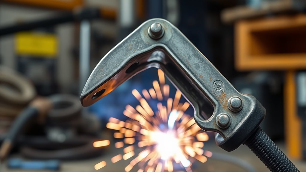
A welding ground clamp connects the workpiece to the work lead from the welding power source. The electrode or wire carries current toward the arc, and the work lead provides the return side of the welding circuit.
The clamp must create a mechanically secure and electrically adequate connection. The OSHA arc-welding standard requires the work lead to be firmly attached and says work connections must be mechanically strong and electrically adequate for the required current.
Paint, rust, mill scale, oil, heavy dirt, and weld spatter can reduce the effective contact area. Resistance at that small contact point converts electrical energy into heat instead of carrying current efficiently through the welding circuit.
A poor connection may contribute to difficult arc starts, intermittent output, erratic arc behavior, excessive heating, or voltage loss. It should be checked before you assume that the welder, wire feeder, electrode, shielding gas, or settings are at fault.
Work Clamp vs. Protective Ground
Although welders often call it a ground clamp, work clamp is the clearer technical term. The work clamp carries normal welding current. The green or green-and-yellow protective grounding conductor in the power cord serves a different safety function.
Lincoln Electric’s grounding and arc-welding guidance explains that a workpiece connection is often incorrectly called a ground clamp and that the work lead should not be confused with the conductor used to ground the machine frame.
Note: Connecting the work clamp does not correct a missing, damaged, or improperly installed protective equipment ground. Equipment installation and supply-circuit grounding must follow the welder manual and applicable electrical rules.
The work clamp completes the welding-current circuit; it is not a substitute for the machine’s protective equipment ground.
Key Components of Welding Work Clamps
Each part of the clamp-and-lead assembly affects resistance, heat, and reliability. Inspect the entire current path rather than looking only at the clamp jaws.
Cable and Connector Design
The electrical cable carries current between the workpiece and the welding power source. Its required size depends on more than the welder’s maximum amperage.
Lincoln Electric’s cable-sizing guidance uses the combined length of the electrode cable and work cable, welding current, and duty cycle. Longer circuits generally need larger conductors to control voltage drop and heating.
The conductor may be copper or another material approved by the lead manufacturer. Do not assume that two cables with the same outside diameter or gauge have the same capacity. Use the welder manual or a manufacturer cable chart.
Check the insulation, cable strands, terminal studs, plugs, lugs, and strain relief. Loose lugs and damaged strands can reduce the effective conductor area and concentrate heat at a connection.
Clamp Attachment Mechanism
The attachment mechanism supplies pressure at the contact surface. Common designs use a spring-loaded jaw, threaded screw, lever, magnetic base, or rotary connection.
Conductive jaw surfaces may be made from copper alloy, brass, plated steel, or another manufacturer-specified material. A clamp body can be strong while still making poor electrical contact if the actual jaw faces are dirty, worn, painted, or touching the workpiece at only one small point.
| Component | Function | What to Inspect |
|---|---|---|
| Clamp jaws or contact pads | Transfer current to the workpiece | Spatter, paint, rust, pitting, distortion, and limited contact area |
| Spring, screw, or lever | Maintains clamping pressure | Weak pressure, stripped threads, cracks, or binding |
| Cable lug or clamp fastener | Joins the cable conductor to the clamp | Loose hardware, corrosion, discoloration, or overheated insulation |
| Welding cable | Carries current back to the power source | Cuts, burns, exposed conductor, crushed areas, stiff sections, or damaged insulation |
| Machine connector | Connects the work lead to the output terminal | Loose fit, damaged threads, arcing marks, heat damage, or incorrect connector size |
A solid brass or copper-alloy clamp can provide good electrical conductivity, but material alone does not guarantee performance. Contact pressure, jaw area, cable attachment, cleanliness, current rating, and duty cycle all matter.
Types of Welding Work Clamps
| Clamp Type | Best Use | Advantages | Limitations |
|---|---|---|---|
| Spring-jaw clamp | General repair, fabrication, and frequent repositioning | Fast to attach and remove | Spring pressure can weaken; jaws may touch uneven surfaces at only one point |
| Screw or C-clamp | Long welds, high current, thick plate, or uneven work | Strong, adjustable contact pressure | Slower to reposition and easy to overtighten on thin material |
| Magnetic clamp | Clean, flat ferromagnetic steel where jaws cannot grip | Quick placement on large flat surfaces | Does not hold on nonmagnetic materials and can collect metal particles or spatter |
| Rotary work connection | Positioners, turntables, pipe rollers, and rotating fixtures | Provides a designed current path while the work rotates | Must be rated and maintained for the application; ordinary bearings are not substitutes |
For example, ESAB lists copper-alloy rotary work clamps in several amperage capacities for rotating fixtures. The important point is not to route welding current through an ordinary bearing, roller, or improvised rotating joint.
Why Work-Clamp Quality Matters
Connection Resistance and Heat
A small amount of resistance becomes important when high welding current passes through a limited contact area. Loose hardware, weak pressure, corrosion, or a dirty surface may create a localized hot spot.
Stop welding if the clamp or its cable connection becomes unusually hot during normal use. Allow the equipment to cool, switch off the power source, and inspect the complete work-lead assembly before continuing.
Arc Stability and Voltage Loss
A sound work connection helps the power source deliver current without unnecessary loss in the return circuit. A badly resistive connection can contribute to erratic starts, output fluctuations, or lower voltage at the arc.
However, the clamp is only one troubleshooting variable. Incorrect polarity, poor machine settings, excessive stickout, contaminated filler metal, poor shielding gas, dirty base metal, and operator technique can produce similar symptoms. Correct amperage and voltage settings remain essential.
Work-Clamp Placement and Arc Blow
Magnetic arc blow is not simply a loose-clamp problem. It is most common with direct-current welding and can be affected by magnetic fields, joint shape, welding direction, current level, and the location of the work connection.
Lincoln Electric’s arc-blow guidance recommends changing work-connection placement as one possible corrective step. Moving the connection may change the magnetic forces acting on the arc.
Note: First correct dirty or loose contact. If the connection is sound but a DC arc still wanders, evaluate work-lead placement, welding direction, current, joint geometry, residual magnetism, and whether AC is permitted by the procedure.
Where Should You Attach a Welding Work Clamp?
Attach the clamp to clean, bare metal on the workpiece whenever practical. Place it close enough to the weld to create a direct current path, but far enough from the arc, sparks, and hot metal to protect the clamp and cable.
ESAB recommends placing the work clamp as close as possible to the arc and removing paint, rust, and coatings that interfere with conductivity.
Good Clamp Locations
- Clean bare metal on the same plate, tube, frame section, or weldment being welded
- A prepared tab or fixture designed to carry the welding current
- A clean steel welding table when the workpiece has broad, reliable metal-to-metal contact with the table
- A manufacturer-approved rotary work connection on rotating equipment
Locations and Current Paths to Avoid
- Painted, rusty, oily, or heavily scaled metal
- Gas cylinders, fuel containers, or pressure vessels not covered by an approved welding procedure
- Chains, wire ropes, cranes, hoists, or elevators
- Threaded pipe joints or other connections that may spark or overheat
- Ordinary bearings, hinges, rollers, bushings, or sliding surfaces
- A distant frame location that forces welding current through electronic equipment or sensitive assemblies
- Loose scraps that merely touch the workpiece
OSHA specifically states that chains, wire ropes, cranes, hoists, and elevators must not carry welding current. It also requires adequate bonding or current-collecting devices when a structure, conveyor, or fixture is regularly used as a return circuit.
Warning: When welding on a vehicle, powered machine, or equipment containing electronics or bearings, follow the equipment manufacturer’s service instructions. Place the work clamp so the intended current path remains close to the repair and does not cross sensitive or moving components.
Step-by-Step: How to Attach a Welding Work Clamp
Before you weld, create a clear, dry work area and inspect the entire welding circuit. A reliable work connection usually takes only a few minutes to prepare.
Before You Begin
Gather the following:
- A welding machine with the correct work lead
- A work clamp rated for the expected current and duty cycle
- A clean workpiece or suitable welding table
- A wire brush, scraper, or grinder for surface preparation
- Required helmet, gloves, flame-resistant clothing, footwear, and other PPE
Warning: Do not weld with exposed conductors, badly damaged insulation, a loose cable lug, broken jaws, or a clamp that overheats. Remove defective equipment from service and follow the applicable workplace rules and manufacturer repair instructions.
- Switch off the welder before changing connections. Follow the power source manual, especially when changing polarity, moving output leads, or handling exposed output terminals.
- Choose a direct current path. Select a location on the same conductive assembly as the weld. Avoid bearings, hinges, chains, electronics, and loosely connected fixtures.
- Prepare the contact area. Remove paint, rust, oil, mill scale, heavy dirt, and spatter until the clamp can touch clean metal.
- Attach the clamp firmly. Seat the conductive jaw faces flat against the metal. Confirm that the clamp cannot slide or rock.
- Connect the work lead to the proper machine output. Use the terminal and polarity specified by the electrode, welding procedure, and power-source manual.
- Route the cable safely. Keep it away from sharp edges, hot metal, sparks, vehicle traffic, standing water, and walkways.
- Spread out excess cable. Do not leave high-current welding cable tightly coiled. OSHA warns that coiled welding cable can overheat and damage its insulation.
- Make a controlled test weld. Use scrap or a permitted test area. Stop and recheck the circuit if the arc starts poorly, cuts out, or the connection heats quickly.
Dry filler metal and correct consumable storage also matter. Knowing why some welding rods need controlled dry storage helps prevent moisture-related weld problems that a new clamp cannot correct.
Pro Tip: When troubleshooting thin sheet or an intermittent arc, clamp directly to the workpiece instead of relying on contact through a table, fixture, hinge, or stack of loose parts.
Troubleshooting Welding Work-Clamp Problems
Check the work connection early when you notice difficult starts, an intermittent arc, unexpected heat, or output that changes as the cable moves.
- Check the contact point: Confirm that both conductive jaw faces touch clean, bare metal.
- Inspect the clamp: Look for pitted jaws, weak spring pressure, stripped screw threads, cracks, corrosion, or heat discoloration.
- Inspect the cable-to-clamp joint: Check for loose hardware, broken strands, green corrosion, burned insulation, or movement at the lug.
- Inspect the full lead: Look for cuts, crushed areas, stiff sections, exposed conductors, previous arcing, or damaged connectors.
- Check machine connections: Make sure output plugs or studs are fully engaged and configured for the required polarity.
- Watch for heat: Stop if the clamp, lug, connector, or cable becomes unusually hot.
- Separate clamp symptoms from other weld problems: Verify polarity, settings, electrode condition, wire feeding, shielding gas, base-metal cleanliness, and technique.
Use proper protective clothing whenever you inspect or test a welding setup near hot metal, sparks, or an energized arc.
Frequent Work-Clamp Errors and Their Solutions
| Symptom | Possible Work-Circuit Cause | Corrective Action | Also Check |
|---|---|---|---|
| Arc starts poorly | Dirty contact point or limited jaw contact | Prepare bare metal and reseat the clamp | Polarity, electrode condition, wire contact tip, and machine settings |
| Clamp or lug gets hot | Loose fastener, corrosion, weak pressure, small contact area, or inadequate rating | Stop welding; clean, tighten, or replace the affected part | Cable size, total circuit length, amperage, and duty cycle |
| Arc cuts in and out | Broken strands, loose lug, damaged connector, or clamp movement | Remove power and inspect the complete work lead | Input power, gun cable, electrode holder, and wire feeder |
| Excessive spatter | Possible unstable output from a poor connection | Improve the work connection and retest | Voltage, wire speed, polarity, gas, stickout, and contaminated metal |
| Unexpectedly low heat at the arc | Possible voltage loss in an undersized or resistive work circuit | Inspect cable size, length, connectors, and clamp contact | Machine output, extension supply, settings, travel speed, and joint design |
| Arc wanders in DC welding | Work-connection position may contribute to magnetic arc blow | Try an approved alternate connection location | Current, welding direction, residual magnetism, joint geometry, and AC suitability |
A work-clamp fault does not directly cause every poor weld. For MIG welding, also inspect related parts such as the liner, contact tip, spool tension, and drive rollers when the welder is not feeding wire correctly.
How to Test a Welding Work Lead Safely
A visual and mechanical inspection should come first. A basic resistance or continuity check can then help identify a completely open lead, broken connection, or severe resistance problem.
- Shut down and isolate the power source. Turn off and unplug the welder when the manual permits. Follow the manufacturer’s shutdown procedure for engine-driven, inverter, or capacitor-equipped equipment.
- Disconnect the work lead if required. Do not place an ohmmeter across an energized welding output.
- Inspect and clean the test points. Dirty meter contact can look like lead resistance.
- Check the meter leads first. Touch the probes together so you know the resistance contributed by the meter and probes.
- Measure from the machine-end connector to the clamp contact face. Flex the cable gently while observing the reading. A reading that jumps may indicate a broken conductor or loose connection.
- Return the equipment to its approved configuration. Reconnect, tighten, and inspect all covers and terminals before restoring power.
Note: A handheld meter uses very little current. A lead can pass a continuity test yet still overheat or lose excessive voltage at welding current. Loaded voltage-drop testing should be performed only by a qualified person using the equipment manufacturer’s procedure.
Tips for Maintaining Your Welding Work Clamp
Regular maintenance helps preserve contact pressure, conductor capacity, and insulation integrity.
- Clean the contact faces: Remove rust, oxidation, paint, and hardened spatter without removing excessive jaw material.
- Clean magnetic clamps carefully: OSHA specifically requires adherent metal particles and spatter to be removed from magnetic work-clamp contact surfaces.
- Inspect pressure mechanisms: Check springs, pivots, screws, and levers for wear or binding.
- Check electrical fasteners: Follow the clamp or welder manufacturer’s torque instructions where provided.
- Inspect the cable: Remove damaged equipment from service if insulation is cut, burned, cracked, or exposing conductor.
- Store it dry: Keep the clamp off damp floors and away from grinding dust, corrosive chemicals, and traffic.
- Do not use the cable as a handle: Pulling or carrying equipment by the lead strains conductors, lugs, and connectors.
Pro Tip: Mark the clamp and lead with their rated capacity or machine assignment. This reduces the chance of installing a light-duty assembly on a higher-current welder.
Work-clamp condition is only one part of a sound fabrication setup. Correct joint preparation and appropriate fillet-weld sizing also affect the finished joint.
Choosing the Right Welding Work Clamp

The right work clamp must suit the welding current, lead, connector, workpiece shape, and operating environment. Do not choose by jaw size or advertised amperage alone.
Products Worth Considering

Value Pack: The package includes 24 packs of butt welding clamps, enough quantity to meet your daily needs and replacements. Each butt welding clamps is individually wrapped in a small bag, convenient to carry and use.

Amp & Cable Capacity: Rated 300A, fits 1/0–2/0 AWG (50–70 mm²) cables, offering secure, stable connection between welder and workpiece for firm grounding.

【Sturdy Third Hand Soldering Tool for Hands Free Precision】 This soldering third hand tool holds your workpiece securely in place, giving you an extra hand to focus on precise soldering, welding, and modeling tasks. No more struggling to hold small parts steady while you work, allowing you to achieve clean, accurate results every time with less frustration.
Work-Clamp Selection Checklist
- Expected welding current: The clamp must carry the current used for the job without excessive heat.
- Duty cycle: Long production welds place more thermal load on the clamp and cable than short, occasional tack welds.
- Total welding-circuit length: Add the full electrode-side and work-side cable lengths when selecting cable size.
- Cable conductor size: Match the lead to the manufacturer’s current, length, and duty-cycle chart.
- Machine connector: Confirm plug type, terminal-stud size, polarity arrangement, and mechanical fit.
- Jaw shape and opening: Choose jaws that make broad contact with flat plate, pipe, angle, or irregular work.
- Clamping pressure: Spring clamps favor speed; screw clamps often provide stronger adjustable pressure.
- Contact material: Consider conductivity, jaw area, corrosion resistance, and replaceable contact parts.
- Environment: Outdoor, damp, abrasive, and high-production environments may require more durable insulation and corrosion protection.
- Approvals and instructions: Follow the welding-machine and clamp manufacturers’ specifications.
Choose high-quality work clamps for high-current or long-duration welding. An oversized amperage label cannot compensate for an undersized cable, loose lug, weak jaw, or poor contact surface.
Polarity and Output-Terminal Selection
The correct terminal depends on the welding process, electrode, wire, and procedure:
- DCEP: The electrode lead connects to positive, and the work lead connects to negative.
- DCEN: The electrode lead connects to negative, and the work lead connects to positive.
- AC: Output alternates polarity, and the machine’s labeled connections and manual control the setup.
- Fixed-output machines: Some welders do not allow the user to reverse output connections.
Warning: Switch off the welding output before moving leads, changing polarity, or touching output studs. Follow the electrode data sheet and welder manual rather than assuming the work lead always belongs on the negative terminal.
Understanding stick-welding amperage for different material thicknesses also helps you determine the current your work lead and clamp must carry.
Frequently Asked Questions
Where should you put a ground clamp when welding?
Attach the work clamp to clean, bare metal on the same conductive assembly as the weld. Keep it reasonably close to the weld while protecting the clamp and cable from sparks and heat. Avoid any location that sends current through bearings, hinges, chains, electronics, or loose joints.
Is a welding ground clamp really a ground?
Not in the same sense as the protective earth or equipment-grounding conductor. The component commonly called a ground clamp is a work clamp that carries welding current back to the power source. The machine frame and supply circuit have separate grounding requirements.
Can you weld with a poor work-clamp connection?
An arc may start, but you should not continue. A poor connection can overheat, arc at the clamp, damage the lead, and create unstable output. Stop, switch off the equipment, clean the contact point, and inspect the clamp and cable.
Can you connect the work clamp to a welding table?
Yes, when the table is designed or suitable for carrying welding current and the workpiece has clean, broad metal-to-metal contact with it. Clamp directly to the workpiece when contact through the table or fixture is uncertain, especially on thin material or during troubleshooting.
Can the clamp go over paint or rust?
Do not rely on contact through paint, heavy rust, oil, thick mill scale, or coatings. Prepare a small area of clean bare metal so the conductive jaw surfaces can make direct contact.
What terminal does the ground clamp use for stick welding?
It depends on the required polarity. For DCEP, the electrode lead connects to positive and the work lead to negative. For DCEN, the connections reverse. AC and fixed-output machines differ, so follow the electrode manufacturer’s polarity guidance and the welder manual.
Why does my welding ground clamp get hot?
Common causes include dirty jaws, limited contact area, weak clamping pressure, corrosion, a loose cable lug, damaged strands, an undersized cable or clamp, excessive circuit length, or operation beyond the rated duty cycle. Stop welding and inspect the complete work circuit.
Are magnetic welding clamps safe to use?
A properly rated magnetic work clamp can be useful on clean, flat ferromagnetic steel. It will not hold correctly on nonmagnetic material, and metal particles or spatter can interfere with its contact surface. Keep the contact face clean and follow the manufacturer’s current rating.
Can you test a work lead with a multimeter?
You can perform a basic continuity or low-resistance check only after the welding power source has been shut down and isolated according to its manual. Never connect an ohmmeter to an energized output. Remember that a low-current meter test cannot prove that the lead will perform correctly at welding current.
Safety Disclaimer: This article is for general information and does not replace professional welding training, an approved welding procedure, workplace safety requirements, electrical codes, or equipment manuals. Follow the welding-machine and consumable manufacturers’ instructions, use appropriate PPE, and have damaged electrical equipment inspected or repaired by qualified personnel.
Conclusion
A welding ground clamp is more accurately called a work clamp because it carries normal welding current rather than serving as the machine’s protective earth ground. Its job is simple, but its condition and placement affect heat, voltage loss, arc behavior, and equipment safety.
Attach the clamp firmly to prepared bare metal, keep the current path direct, and prevent welding current from passing through chains, bearings, electronics, or loose joints. Size both the clamp and cable for the current, total circuit length, and duty cycle.
If the arc becomes unstable or the clamp heats up, stop and inspect the work circuit before changing random machine settings. Better grounding habits, correct parameters, sound joint preparation, and continued training all improve welding consistency. Learning about professional welding certification and career development can also support safer, more informed work over time.
Sources
- OSHA 29 CFR 1910.254 — Arc Welding and Cutting — work-lead attachment, machine grounding, cable handling, maintenance, and prohibited current paths.
- Lincoln Electric — Grounding and Arc Welding Safety — distinction between the work lead and protective grounding.
- Lincoln Electric — Selecting the Proper Size Welding Cables — current, duty-cycle, resistance, and circuit-length considerations.
- Lincoln Electric — Prevent Arc Blow — magnetic arc-blow causes and work-connection placement.
- Miller — Welding Safely in the Home Shop — metal-to-metal work-clamp contact and wet-area precautions.
- ESAB — Weld-Joint Preparation Guide — placing the work clamp near the arc and removing coatings that interfere with conductivity.




